

Honeywell V94 DATASHEET
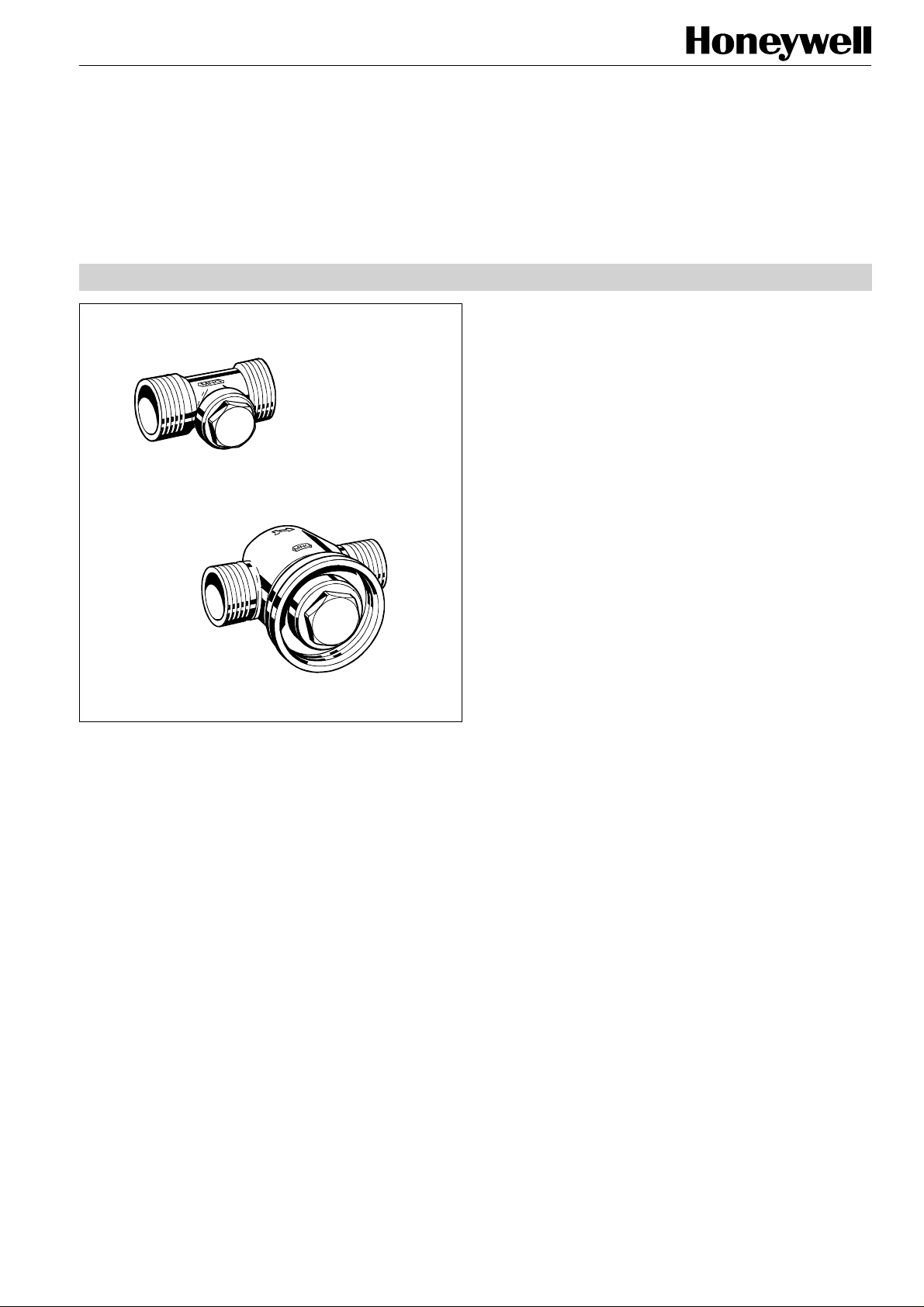
V94 Series
Lockshield Valves
CONNECTIONS FOR HEAT EXCHANGERS, PN10, FLAT SEALING
PRODUCT DATA
Application
V94 Series Lockshield Valves are used in the supply and
return of heat exchangers in hydronic cooling and heating
systems. They have the following functions:
•
Shut-off: by closing the valve the flow through the heat
exchanger is shut-off.
•
Pre-setting: the flow through the heat exchanger can be
throttled to meet system requirements
vs
V9400 in DN15 (k
valve when a draining adapter is used (accessory, not
supplied with the valve).
The valves have flat sealing external threads on inlet and
outlet. Refer to chapter ‘Accessories’ further below for
suitable union nuts and tailpieces.
Features
• Robust, noise and flow optimised valve housing made
of corrosion resistant red bronze
• Available with various kvs-values
• Optional flow direction
• Shut-off and pre-setting functions
• V9400 also with draining function
1,45) also supports draining over the
Design
•
Valve housing PN10, DN15 with 3/4" external threads,
DN20 with 1" external threads or DN25 with 1 1/4" external
threads, flat sealing
•
Valve insert
•
Protection cap
Materials
•
Valve housing made of red bronze RG5 according to
DIN 1705 (G-CuSn5ZnPb), V9400 additionally matt nickelplated
•
Valve insert made of brass with EPDM O-rings
•
Protection cap made of brass with Teflon sealing, V9400
additionally nickel-plated
Copyright © 2001 Honeywell AG • All rights reserved EN0H-0151GE25 R0501
Specifications
Medium
pH-value
Operating temperature
Operating pressure
vs
(cv)-values
k
Leakage rate
Rangeability
Water or glycol-water mixture
8...9,5
2...130°C (36...266°F)
max. 10 bar (156 P.S.I.)
1,7...5,0 (1,98...5,81)
see Table 2 on page 35
vs
0,02% of k
50 : 1
-value
V94 SERIES
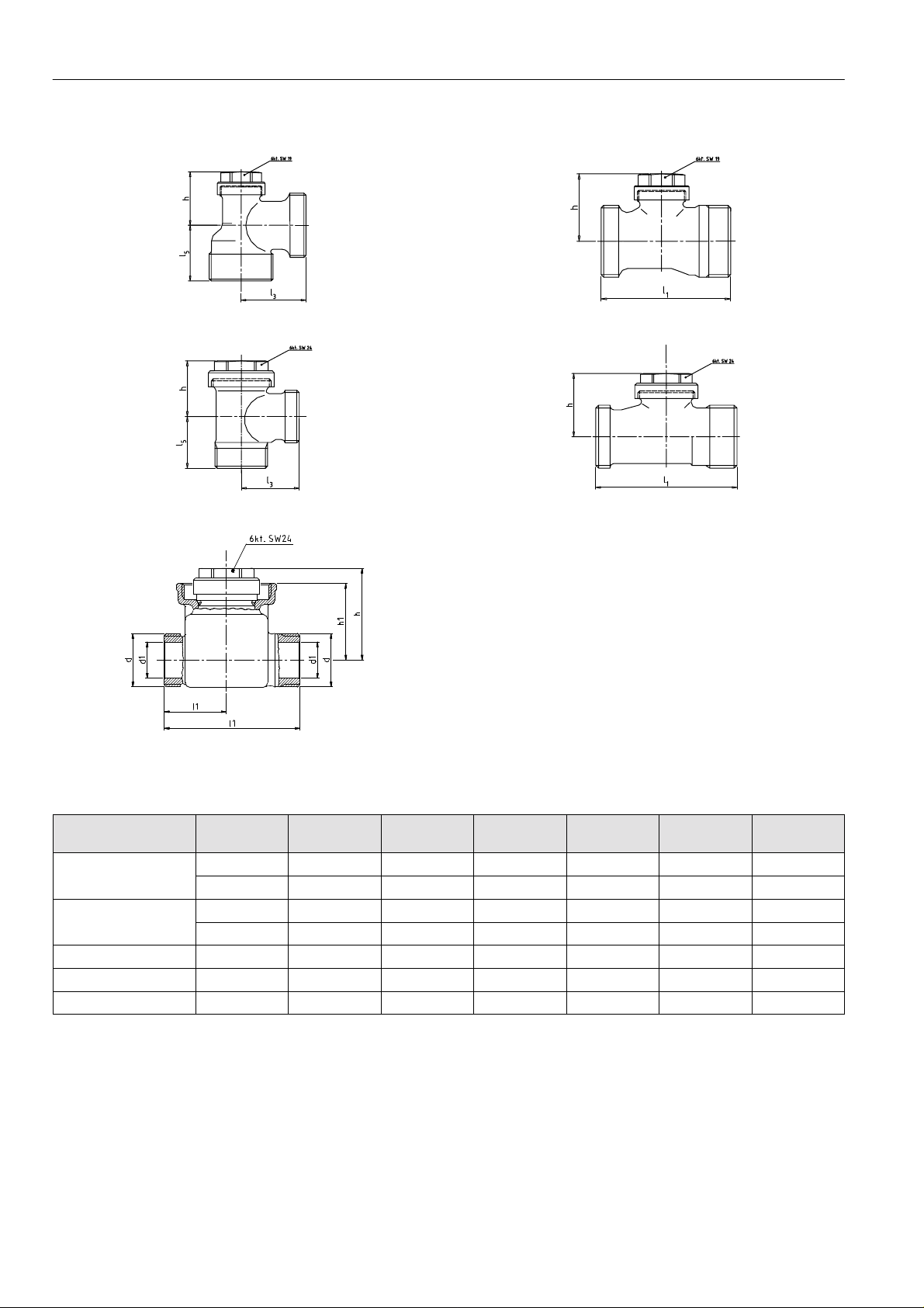
Dimensions
Fig. 1. V9400 angle
Fig. 3. V9441 angle
Fig. 5. V9440 straight
Fig. 2. V9400 straight
Fig. 4. V9441 straight
Table 1: Dimensions
Item DN Connection l
1
3
l
5
l
h Spanner
size cap
V9400 angle 15 1/2” — 29 26 25 19
20 3/4” — 34 29 29 19
V9400 straight 15 1/2” 51 — — 32 19
20 3/4” 59 — — 32 19
V9441 angle 15 1/2” — 29 26 28 24
V9441 straight 15 1/2” 66 — — 33 24
V9440 straight 20 1” 75 — — 45 24
NOTE: All dimensions in mm unless otherwise stated.
EN0H-0151GE25 R0501 2 Honeywell AG • All rights reserved
Ordering Information
Type Version DN kvs-value cv-value OS-No.
V9400 angle 15 1,70 1,98 V9400EX015
angle 20 1,70 1,98 V9400EX020
straight 15 1,45 1,69 V9400DX015
straight 20 1,50 1,74 V9400DX020
V9441 angle 15 4,00 4,65 V9441EX015
straight 15 2,20 2,56 V9441DX015
V9440 straight 20 5,00 5,81 V9440DX020
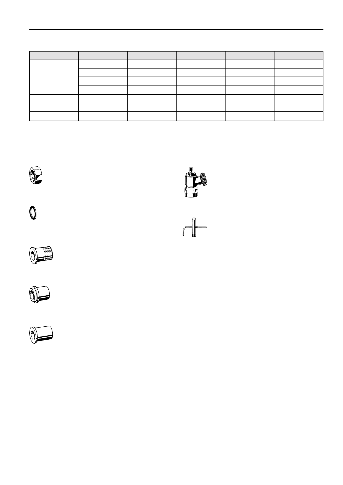
Accessories
V94 SERIES
Connections
Nickel-plated brass union nut
for valves DN10 VA5000B010
for valves DN15 VA5000B015
for valves DN20 VA5000B020
PTFE sealing ring
for valves DN10 VA5090A010
for valves DN15 VA5090A015
for valves DN20 VA5090A020
Externally threaded brass tailpiece, flat sealing
3/8”, for valves DN10 VA5500A010
1/2”, for valves DN15 VA5500A015
3/4”, for valves DN20 VA5500A020
Brass soldering tailpiece, flat sealing
12 mm, for valves DN10 VA5930A012
15 mm, for valves DN15 VA5930A015
22 mm, for valves DN20 VA5930A020
Accessories
Draining adapter
for V9400 VA3300A001
Special tool
for V9400 VA8300A001
Steel welding tailpiece, flat sealing
DN10 VA5940A010
DN15 VA5940A015
DN20 VA5940A020
Honeywell AG • All rights reserved 3 EN0H-0151GE25 R0501
 Loading...