

Page 1
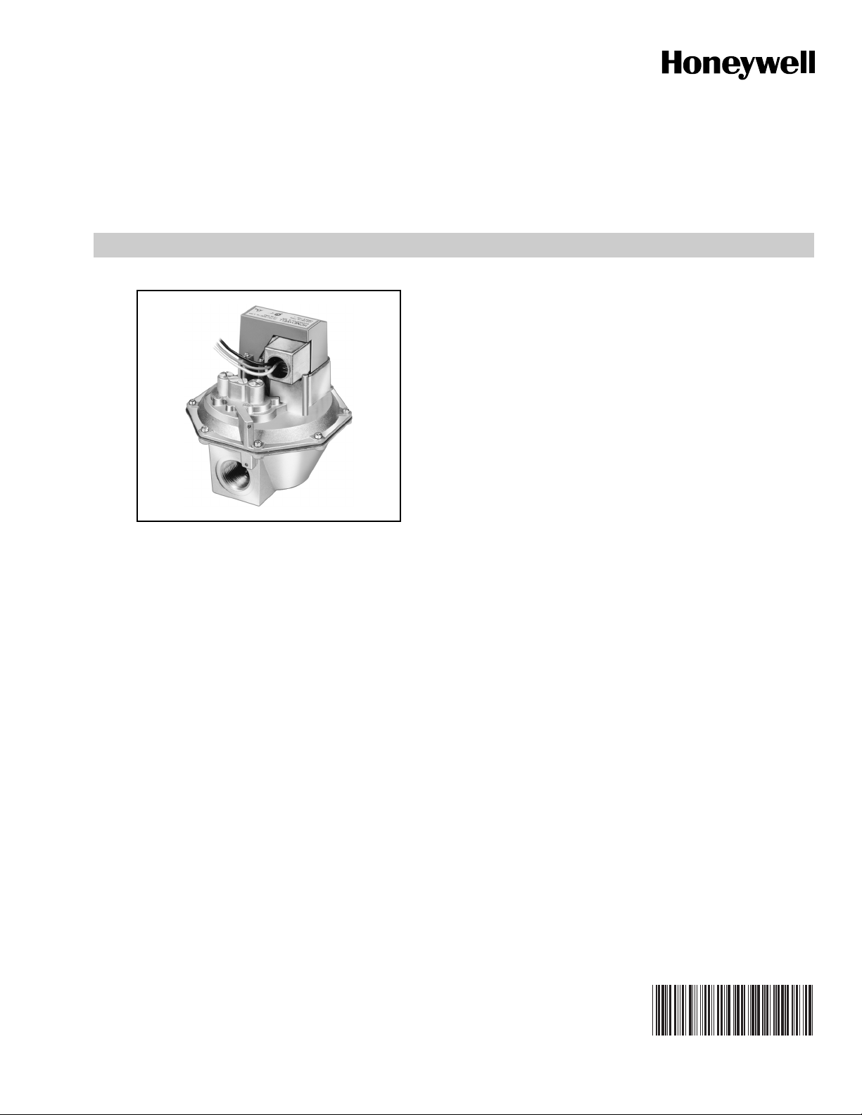
V4943A/V8943A
On/Off Diaphragm Gas Valves
FEATURES
• V4943A used with line voltage, two-wire thermostat or
controller.
• V8943A used with 24 Vac thermostat or controller.
• Valves open in less than six seconds.
• Rated for 0.5 psi (3.4 kPa).
• Rated for -40°F to +150°F (-40°C to 66°C).
• Firm closing; diaphragm is spring-loaded.
• Valves close on power failure; recommended for final
shutoff service.
• 1/4 in. (6 mm) spade terminal electrical connections.
Leadwires and cover for electrical conduit connections
are provided.
• Designed as replacement valves for V4843A/V8843A.
APPLICATION
PRODUCT DATA
The V4943A and V8943A are solenoid-operated diaphragm
valves suitable for Liquefied Petroleum (LP) and natural
gases. They are normally used on atmospheric boilers,
commercial water heaters, and rooftop heaters.
Contents
Application......................................................................... 1
Features ............................................................................ 1
Specifications .................................................................... 2
Ordering Information ......................................................... 2
Installation ........................................................................ 4
Wiring ................................................................................ 6
Operation........................................................................... 7
Checkout and Troubleshooting.......................................... 7
65-0212-2
Page 2

V4943A/V8943A ON/OFF DIAPHRAGM GAS VALVES
SPECIFICATIONS
Models (See Table 1):
V4943A (120 Vac) solenoid-operated diaphragm valves for
0.5 psi (3.4 kPa) internal bleed.
V8943A (24 Vac) solenoid-operated diaphragm valves for
0.5 psi (3.4 kPa) internal bleed.
.
Table 1. Models Available.
Maximum
Operating
Model
V4943A 120V/60 Hz 0.5 3.4 1, 1-1/4,
V8943A 24V/60 Hz 0.5 3.4 1, 1-1/4,
Type of Gas:
Liquefied petroleum (LP) and natural gas.
Flow Capacity:
See Table 2.
Model
V4943A
V8943A
Valve Pattern:
Straight-through, non-offset.
Valve Body Material:
Die-cast aluminum.
Voltage and
Frequency
Table 2. V4943A/V8943A Flow Capacity.
Valve
Size
(in.)
1 1,000,000
1-1/4 2,100,000
1-1/2 2,500,000
2 3,000,000
Pressure
CSA Rating for 0.64 sp gr
Gas at 1 in. wc.
Pressure Drop
Pipe Size
(in.)
1-1/2, 2
1-1/2, 2
Thread
Typ e (psi) (kPa)
NPT
NPT
Electrical Ratings:
V4943A Frequency:
60 Hz.
V4943A Current:
0.055A maximum at rated voltage and frequency.
V8943A Frequency:
50/60 Hz.
V8943A Current:
0.363A maximum at rated voltage and frequency.
Electrical Terminations:
1/4 in. (6 mm) spade terminals (quick connects). Leadwires
and cover for electrical conduit connections are provided.
Valve Opening Time:
Six seconds maximum.
Valve Closing Time:
On power failure, a maximum of 3 seconds at 7 in. wc inlet
pressure.
Power Consumption:
V4943A: 6 VA maximum.
V8943A: 8 VA maximum.
Ambient Temperature Ratings:
-40°F (-40°C) to 150°F (66°C)
Dimensions:
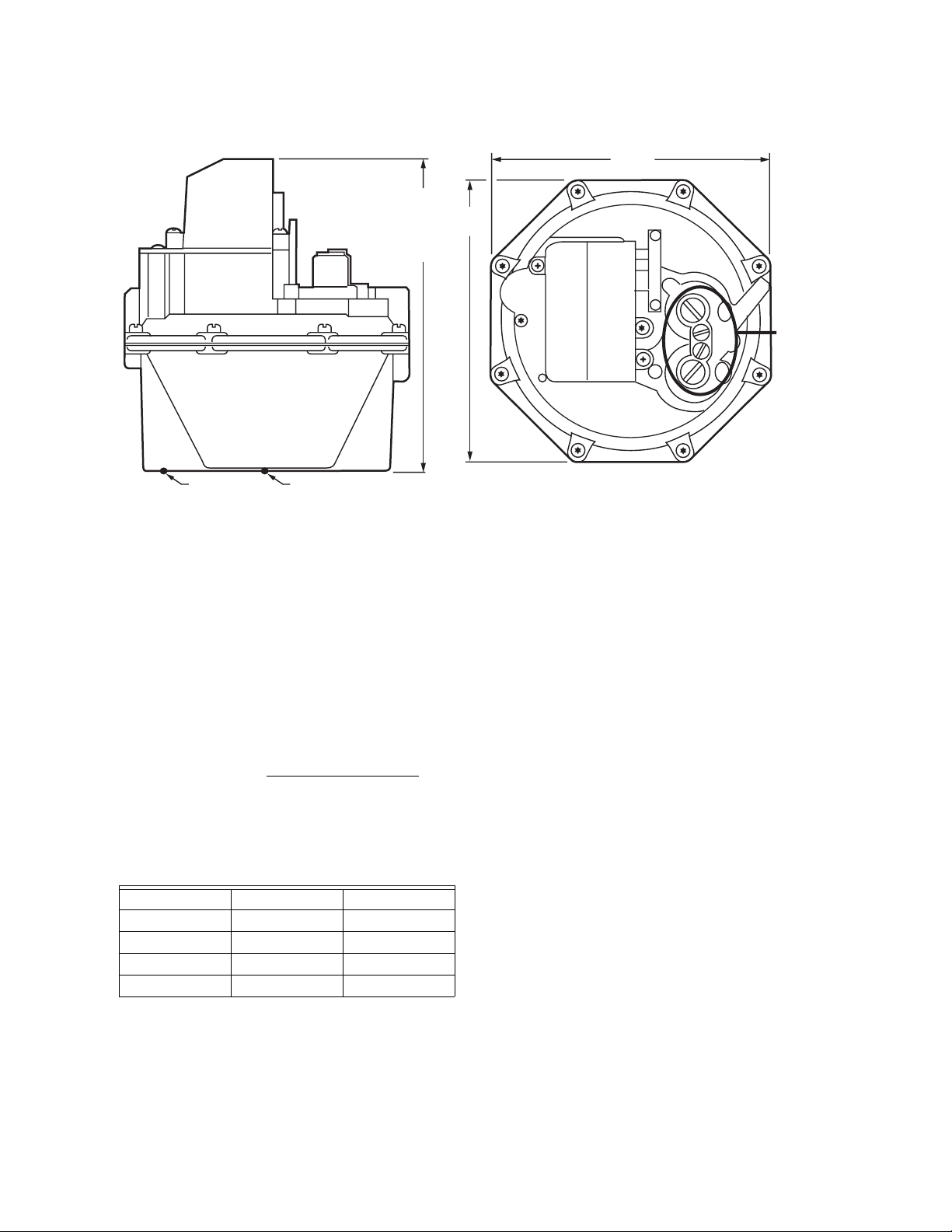
See Fig. 1.
Weight:
1, 1-1/4 in. valves: 4 lb (1.8 kg).
1-1/2, 2 in. valves: 5 lb (2.3 kg).
Mounting Position:
Upright (horizontal).
Approvals:
Underwriters Laboratories Listed: File Number MH1639,
Guide Number YIOZ.
CSA Certified: Report Number C2030020.
Accessory:
AT72D Transformer (40 VA) for all 24 Vac models.
ORDERING INFORMATION
When purchasing replacement and modernization products from your TRADELINE® wholesaler or distributor, refer to the
TRADELINE® Catalog or price sheets for complete ordering number.
If you have additional questions, need further information, or would like to comment on our products or services, please write or
phone:
1. Your local Honeywell Automation and Control Products Sales Office (check white pages of your phone directory).
2. Honeywell Customer Care
1885 Douglas Drive North
Minneapolis, Minnesota 55422-4386
In Canada—Honeywell Limited/Honeywell Limitée, 35 Dynamic Drive, Scarborough, Ontario M1V 4Z9.
International Sales and Service Offices in all principal cities of the world. Manufacturing in Australia, Canada, Finland, France,
Germany, Japan, Mexico, Netherlands, Spain, Taiwan, United Kingdom, U.S.A.
65-0212—2 2
Page 3
V4943A/V8943A ON/OFF DIAPHRAGM GAS VALVES
SIDE VIEW
6-9/16 (167)
FOR 1, 1-1/4
OR
7-3/8 (187)
FOR 1-1/2, 2
INLET
PRESSURE
TAP
OUTLET
PRESSURE
TAP
Fig. 1. V4943/V8943 dimensions in in. (mm).
Gas Valve Sizing
1. Check the burner nameplate for (a) the type of gas used,
and (b) the gas flow capacity. The capacity is listed in
British thermal units per hour (Btuh) or in cubic feet per
hour (cfh).
2. Contact the local gas utility for information regarding (a)
the specific gravity (sp gr) and (b) the Btu per cubic foot
(Btu/cf) for the type of gas used.
3. Find the capacity in cfh. If the capacity is listed in Btu,
convert to cfh by the following formula:
Capacity in cfh = Btuh (burner nameplate)
Btu/cf (gas utility)
6
(152)
TOP VIEW
6 (152)
PRESSURE
ADJUSTMENT
NOT APPLICABLE
TO V4943A/V8943A
M23369
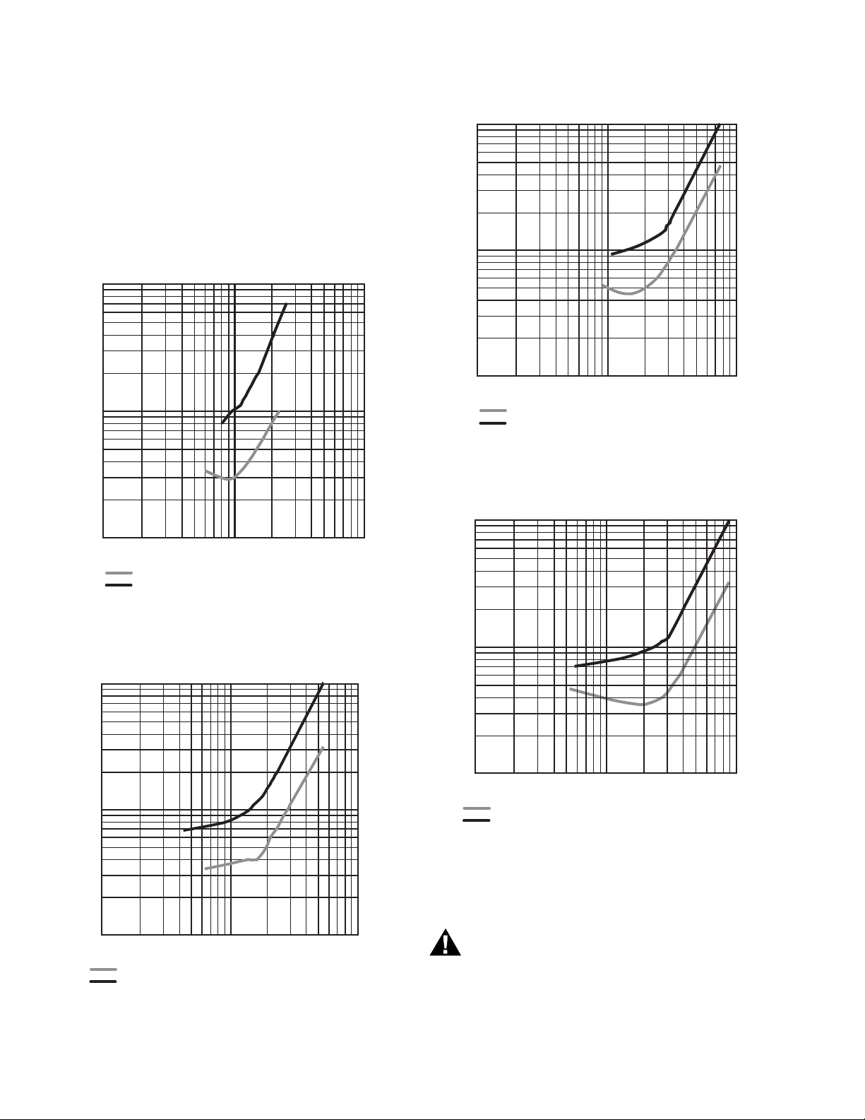
5. Use the corrected capacity in cfh when determining the
gas valve size in Fig. 2–5.
6. Determine the maximum pressure drop across the valve
and draw a vertical line at this pressure on Fig. 2, 3, 4, or
5.
7. At the point of intersection of the vertical line and the
curve, draw a horizontal line to intersect the flow (capacity) scale. The point of intersection indicates the capacity
that can be obtained with the maximum pressure drop.
8. If the capacity at the maximum pressure drop is insuffi-
cient, use the capacity vs. pressure drop curve for the
next larger valve size and repeat steps 6 and 7.
4. For gases with specific gravities other than 0.64, multiply
the burner cfh by the proper conversion factor in Table 3.
Table 3. Gas Conversion Factors.
Type of Gas sp gr (average) Multiply cf/h by
Manufactured 0.60 0.968
Mixed 0.70 1.046
LP-Propane 1.53 1.546
LP-Butane 1.98 1.759
3 65-0212—2
Page 4
V4943A/V8943A ON/OFF DIAPHRAGM GAS VALVES
Sizing Two Identical Valves Piped in Series
1. Find the cfh for the type of gas used.
2. Consider both valves as one unit. Determine the maxi-
mum pressure drop across the one unit.
3. Find the pressure drop across the first valve by assum-
ing it to be 45 percent of the total pressure drop.
4. Find the valve size in Fig. 2–5.
The second valve will be the same size as the first valve.
10
1
IN. WC PRESSURE DROP
0.1
100
V4943/8943A 1 IN. VALVE
1,000
FLOW (CFH)
SERIES "MEASURED AT VALVE PRESSURE TAPS"
SERIES "MEASURED AT PIPE PRESSURE TAPS"
10,000
M23370
10
1
IN. WC PRESSURE DROP
0.1
100
V4943/8943A 1-1/2 IN. VALVE
1,000
FLOW (CFH)
SERIES "MEASURED AT VALVE PRESSURE TAPS"
SERIES "MEASURED AT PIPE PRESSURE TAPS"
10,000
M23372
Fig. 4. Capacity vs. pressure drop curves for 1-1/2 in.
valve.
10
V4943/8943A 2 IN. VALVE
Fig. 2. Capacity vs. pressure drop curves for 1 in. valve.
10
2.5
1.5
1
IN. WC PRESSURE DROP
2.5
1.5
0.1
100
V4943/8943A 1-1/4 IN. VALVE
1,000
FLOW (CFH)
SERIES "MEASURED AT VALVE PRESSURE TAPS"
SERIES "MEASURED AT PIPE PRESSURE TAPS"
10,000
M23371
Fig. 3. Capacity vs. pressure drop curves for 1-1/4 in.
valve.
1
IN. WC PRESSURE DROP
0.1
100
SERIES "MEASURED AT VALVE PRESSURE TAPS"
SERIES "MEASURED AT PIPE PRESSURE TAPS"
1,000
FLOW (CFH)
10,000
M23373
Fig. 5. Capacity vs. pressure drop curves for 2 in. valve.
INSTALLATION
WARNING
Potential Explosion Hazard.
Installation and service by trained professionals only.
Exceeding the pressure rating or use of unspecified
fuel can lead to improper operation of the valve and
can create an explosion hazard. Property damage,
severe bodily injury or death can result.
65-0212—2 4
Page 5
V4943A/V8943A ON/OFF DIAPHRAGM GAS VALVES
When Installing this Product...
1.
Read these instructions carefully. Failure to follow them
could damage the product or cause a hazardous condition.
2. Check the ratings given in the instructions and on the
product to make sure the product is suitable for your
application.
3. Installer must be a trained experienced flame safeguard
control technician.
4. After installation is complete, check out product opera-
tion as provided in these instructions.
CAUTION
Prevent Possible Explosion/Fire Hazard
Prevent Electrical Shock/Equipment Damage
1. Turn off gas supply before starting installation.
2. Disconnect power supply before beginning
installation to prevent electrical shock and
equipment damage.
3. Do not remove seal over valve inlet or outlet until
ready to connect piping.
4. Install valve in a horizontal pipe line in any upright
position with the gas flow in the direction indicated
by the arrow on the casting.
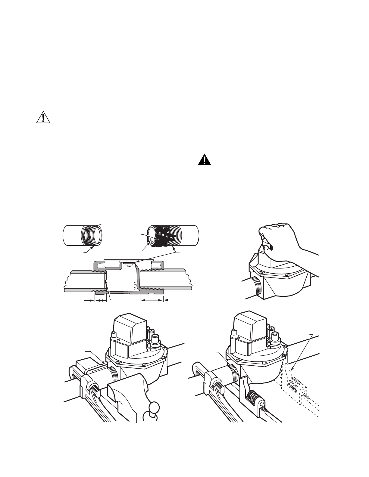
Prepare Piping and Install Valve (Fig. 6).
1. Use new, properly reamed pipe free from chips.
2. Do not thread the pipe too far. Valve distortion or mal-
function can result from excess pipe in the valve.
3. Apply good quality pipe dope, resistant to the action of
LP gas; put a moderate amount of pipe dope on the pipe
threads (not the valve threads). If pipe dope lodges on
the valve seat, it can prevent proper closure.
4. Install the valve in a horizontal pipe line in an upright
position with the gas flow in the direction indicated by the
arrow on the casing.
5. Apply a parallel jaw wrench only to the flat next to the
pipe being installed. A wrench applied to the valve body
itself or to the end farthest from the pipe being inserted
can distort the casting and cause a malfunction.
6. The gas flow must be in the same direction as the arrow
on the bottom of the valve body.
WARNING
Prevent Possible Explosion/Fire Hazard
Install the valve so the gas flow is in the same direction
as the arrow on the bottom of the valve bottom.
7. Make electrical connections as shown in Fig. 7 and 8.
8. Turn on the main gas and, with a soap solution, check
the valve installation for leaks.
CORRECT
NORMAL
FULL THREAD
CORRECT
NORMAL
FULL
THREAD
CORRECT
VISE GRIPS
END NEXT
TO PIPE
BEING
INSERTED
TWO CLEAN
THREADS,
MODERATE
AMOUNT
OF DOPE
EXCESS DOPE CAN PUSH DISK
OFF THE
VALV E
SEAT
LOOSE
CHIPS
REAM PIPE,
BLOW OUT CHIPS (THAT
CAN LODGE ON SEAT)
INCORRECT
TOO LONG;
DISTORTS
VALVE SEAT
INCORRECT
TOO LONG,
DISTORTS
VALVE SEAT
CORRECT
WRENCH
CORRECTLY
APPLIED NEXT
TO PIPE BEING
INSERTED
AVOID
USING
VALVE AS
HANDLE
INCORRECT
WRENCH
HERE STRAINS
VALVE BODY
Fig. 6. Preparing piping and installing valve.
5 65-0212—2
M6877A
Page 6
V4943A/V8943A ON/OFF DIAPHRAGM GAS VALVES
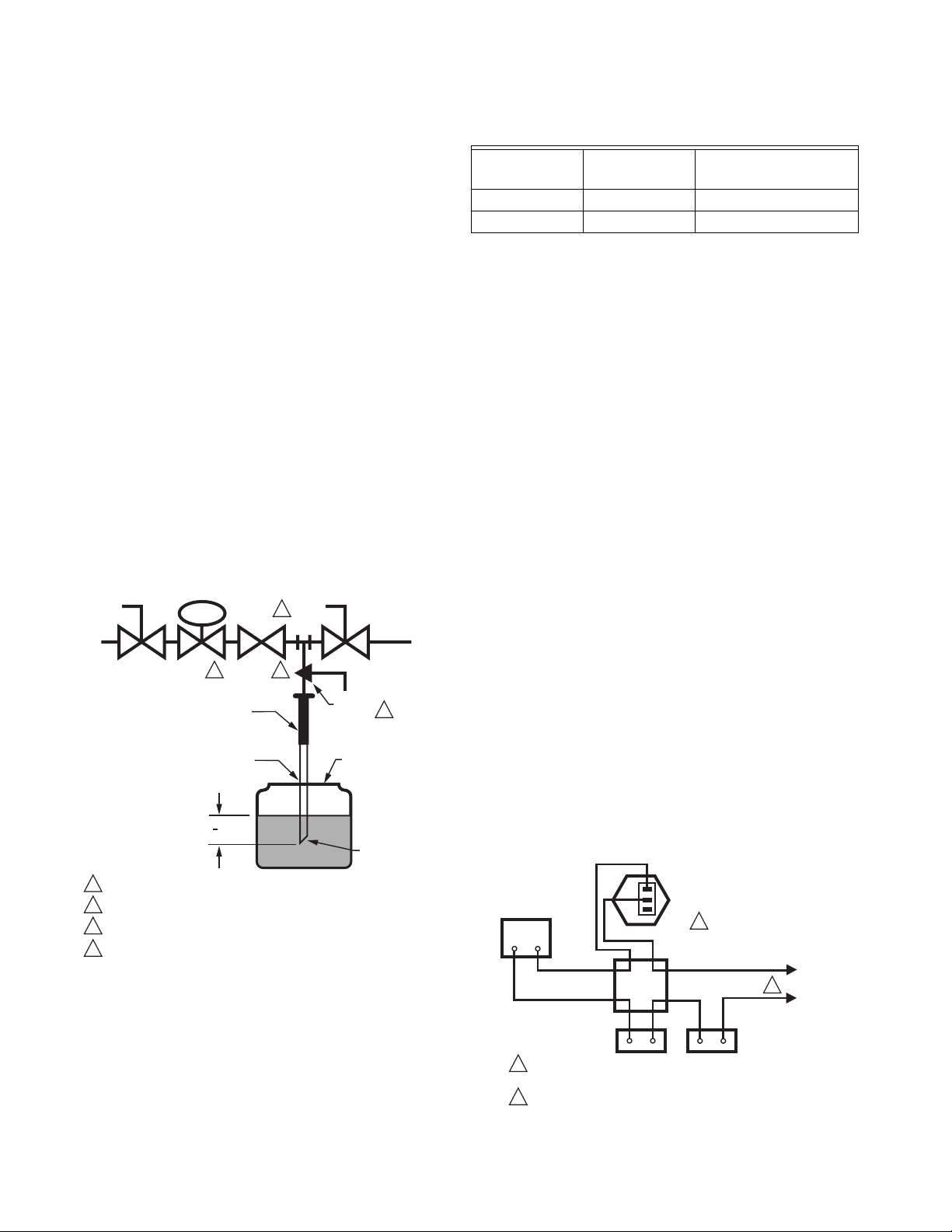
Valve Leak Test (See Fig. 7)
This test checks the tightness closure of a gas safety shutoff
valve. It should be performed by a qualified technician during
the initial startup of a burner system, or whenever the valve is
replaced (see SERVICE INFORMATION section). It is
recommended that this test also be included in scheduled
inspection and maintenance procedures.
1. De-energize the control system to make sure there is no
power to the safety shutoff valve (C) shown in Fig. 8.
2. Close the upstream manual gas cock (A).
3. Make sure the manual test petcock (F) is closed in the
leak test tap assembly (D).
4. Remove the leak test tap plug (valve outlet pressure tap
can be used as a test tap) and connect the test apparatus to the leak test tap (D).
5. Close the downstream manual gas cock (E).
6. Open the upstream manual gas cock (A).
7. Run the safety shutoff valve (C) to its fully open position
(through the safety system); then immediately deenergize the system to close the valve.
8. Immerse a 1/4 in. tube vertically 1/2 in. (13 mm) into a jar
of water.
9. Slowly open the test petcock (F).
10. When the rate of bubbles coming through the water sta-
bilizes, count the number of bubbles appearing during a
ten-second period. Each bubble appearing during a tensecond period represents a flow rate of approximately
0.001 cfh.
DABC E
LEAK
4
TEST
GAS
SUPPLY
UPSTREAM
MANUAL
GAS COCK
CAN ALSO BE A PERMANENT PETCOCK.
1
2
PRV = PRESSURE REGULATING VALVE.
3
SSOV = SAFETY SHUTOFF VALVE.
4
USE ONLY ONE OF THE DOWNSTREAM TAPS ON THE SS0V.
PRV
2 3
1/4 IN. (6 MM)
FLEXIBLE
TUBING
1/4 IN. (6 MM)
ALUMINUM OR
COPPER PILOT
TUBING
1
(13 MM)
2
SSOV
TAP
Fig. 7. Valve leak test.
To meet code requirements, leakage must not exceed the
following values. See Table 4.
DOWNSTREAM
MANUAL
GAS COCK
BURNER
F
MANUAL
TEST
PETCOCK
JAR OR GLASS
WITH WATER
CUT AT
45 DEGREE
ANGLE
1
M9547F
Table 4. Allowable Leakage Rates.
a
Number of Bubbles
per 10 sec
Pipe Size (in.)
Allowable
Leakage
1, 1-1/4 353 13
1-1/2, 2 453 16
a
Based on air standard conditions, test pressures in accordance with ANSI Z21.21, Section 2.4.2 and a maximum of
235 cc/h per inch of seal-off-diameter. Seal-off diameter is not
the same as pipe size.
11. Close the upstream manual gas cock (A).
12. Close the test petcock (F), remove the test apparatus,
and replace the leak test tap plug (D).
13. Open the upstream manual gas cock (A) and energize
the safety shutoff valve (C).
14. Test with soap bubbles to make sure there is no leak at
the test tap (D).
15. De-energize the safety shutoff valve (C).
16. Open the downstream manual gas cock (E).
17. Restore the system to normal operation.
WIRING
1. Disconnect power supply before making wiring connec-
tions to prevent electrical shock and equipment damage.
2. All wiring must comply with applicable electrical codes,
ordinances, and regulations. Use NEC Class 1 (line voltage) wiring.
3. For normal installations, use moisture-resistant number
14 wire suitable for at least 167°F (75°C) when using a
Flame Safeguard Primary Control or a Flame Safeguard
Programming Control.
4. For high temperature installations, use moisture-resis-
tant number 14 wire, selected for a temperature rating
above the maximum operating temperature.
5. Check the power supply circuit. The voltage and fre-
quency must match those of the valve.
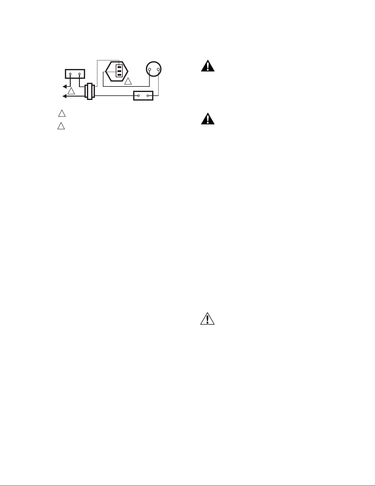
6. Refer to Fig. 8 and 9 for typical field wiring connections.
Follow the burner manufacturer wiring diagram if provided.
7. Make wiring connections using the wires provided with
the valve.
BLACK
AUTOMATIC VALVE
LINE VOLTAGE
THERMOSTAT
OR CONTROLLER
ORANGE
JUNCTION
BOX
LIMIT(S)
1
POWER SUPPLY. PROVIDE DISCONNECT MEANS
AND OVERLOAD PROTECTION AS REQUIRED.
2
THE MV TERMINAL IS NOT USED ON THIS DEVICE.
PV
PV/MV
MV
2
1
FLAME
SAFEGUARD
CONTROL
L2
L1
(HOT)
M6880B
65-0212—2 6
Fig. 8. Typical wiring diagram for V4943A Valve.
Page 7
AUTOMATIC
VALV E
LIMIT(S)
BLACK
L1
(HOT)
1
L2
TRANSFORMER
POWER SUPPLY. PROVIDE DISCONNECT MEANS
1
AND OVERLOAD PROTECTION AS REQUIRED.
2
THE MV TERMINAL IS NOT USED ON THIS DEVICE.
ORANGE
24-VOLT
THERMOSTAT
PV
PV/MV
MV
2
FLAME SAFEGUARD
CONTROL
M6881B
Fig. 9. Typical wiring diagram for V8943A Valve.
OPERATION
Operation of V4943A/V8943A Valves
When the controller is not calling for heat, the valve solenoid
coil is not energized. The plunger in the actuator is in the down
position, closing the bleed port and opening the supply port.
The inlet gas flows into the upper portion of the valve until the
gas pressure above and below the diaphragm is equalized.
The valve closes and remains closed due to the combined
forces of gas and spring pressures.
On a call for heat, the controller contacts close and the valve
solenoid coil is energized. The gas above the diaphragm
bleeds to the downstream outlet of the valve.
As the gas bleeds from above the diaphragm, the gas pressure
is greater below the diaphragm than above and the valve
begins to open. When the gas pressure above the diaphragm
reaches its minimum value (burner delivery pressure), the
valve fully opens.
After the controller is satisfied, the procedure is reversed. The
controller contacts open and the solenoid coil is de-energized.
The plunger is released, moving to the down position. The
bleed port closes and the supply port opens, allowing gas to
flow above the diaphragm. As the gas pressure above the
diaphragm increases, the diaphragm moves downward and
the valve begins to close. When the gas pressures above and
below the diaphragm are equal, the valve fully closes. Spring
pressure assists in closing the valve. If the inlet gas supply fails
and there is no gas pressure above the diaphragm, the spring
pressure is enough to close the valve.
In the event of a power failure during automatic operation of
the valve, the V4943A/V8943A Valves close. Normal operation
resumes on the restoration of power.
V4943A/V8943A ON/OFF DIAPHRAGM GAS VALVES
CHECKOUT AND TROUBLESHOOTING
WARNING
Prevent Possible Explosion Hazard
Do not let fuel accumulate in the combustion chamber.
If fuel is allowed to enter the chamber for longer than a
few seconds without igniting, an explosive mixture
could result.
WARNING
Prevent Possible Explosion Hazard
Do not put the system into service until you have
satisfactorily completed all applicable tests described in
the Checkout section of the instructions for the flame
safeguard control, and any other tests required by the
burner manufacturer.
Close all manual fuel shutoff valves as soon as trouble
occurs.
Checkout
1. Check the performance of the valve by measuring the
pressures at the inlet and outlet pressure taps at the bottom of the valve. The pressure reading at the outlet tap
can be slightly higher than a downstream measurement
due to dynamic gas flow effects. The measurement at
the outlet tap is for reference only.
2. Shut off the gas supply to the valve and make sure the
valve is closed when setting up pressure measuring
equipment.
3. Set the thermostat or controller to energize the valve and
check the final outlet pressure.
4. Start the system and observe its operation through at
least one complete cycle to make sure the valve functions as described in the Operation section.
Troubleshooting
CAUTION
Electrical shock or equipment damage hazard.
Use extreme care during troubleshooting. Line voltage
is present at the actuator for the V4943A Valves, and
present in all controller circuits for all V4943A/V8943A
Val ves.
IMPORTANT
Do not assume that the valve must be replaced until
after all other sources of trouble are eliminated.
The Valve will not Open When Thermostat or
Controller Calls for Heat
1. Check that there is voltage at the valve actuator lead-
wires or terminal block. Be careful of any line voltage at
the actuator of the V4943A Valves.
2. If there is no voltage at the actuator, first make sure line
voltage power is connected to the master switch, the
master switch is closed and overload protection (circuit
breaker, fuse or similar device) has not opened the
power line.
7 65-0212—2
Page 8

V4943A/V8943A ON/OFF DIAPHRAGM GAS VALVES
3.
For V8943A only, if line voltage power is correct, check
the transformer output. Replace the transformer if necessary.
4. If there is still no voltage at the actuator, make sure all
appropriate contacts in the thermostat or controller, limits and flame safeguard control are closed. If one or
more is open, determine the cause(s) and correct the
condition(s) before proceeding.
5. If there is proper voltage at the valve actuator but the
valve still does not open, first check that the gas pressure at the valve is normal.
6. If the valve still does not open, replace the valve.
Service Information
CAUTION
Prevent Electrical Shock/Equipment Damage
• Only qualified service technicians should attempt to
service or repair flame safeguard controls and
burner systems.
• Line voltage is present in the electrical circuits to the
valve. Open the master switch before replacing the
valve.
The Valve does not Open When One or More
Appropriate Contacts in Thermostat or Controller,
Limit(s) or Flame Safeguard Control is Open
1. Make sure that the gas flow is in the direction of the
arrow on the valve body.
Make sure the valve actuator is wired in the correct cir-
2.
cuit.
3. Open the master switch to remove power from the valve
actuator. If the valve does not close, the actuator may
not be wired properly.
4. Check and correct the wiring, if necessary.
5. Look for a possible short in the electrical circuit.
Scheduled Inspection and Maintenance
For periodic inspection and maintenance, set up a schedule
and follow it. Include the burner valves (check for external
leakage around all seals and joints with leak detector; also
check for internal valve seat leakage—see Valve Leak Test
section) and all other controls. For more information, refer to
the flame safeguard control instructions.
Automation and Control Solutions
Honeywell International Inc. Honeywell Limited-Honeywell Limitée
1985 Douglas Drive North 35 Dynamic Drive
Golden Valley, MN 55422 Scarborough, Ontario M1V 4Z9
customer.honeywell.com
® U.S. Registered Trademark
© 2006 Honeywell International Inc.
65-0212—2 M.S. Rev. 05-06
 Loading...