

Page 1
Replacement Bonnet Assembly
for V5055, V5097 Gas Valves
INSTALLATION INSTRUCTIONS
APPLICATION
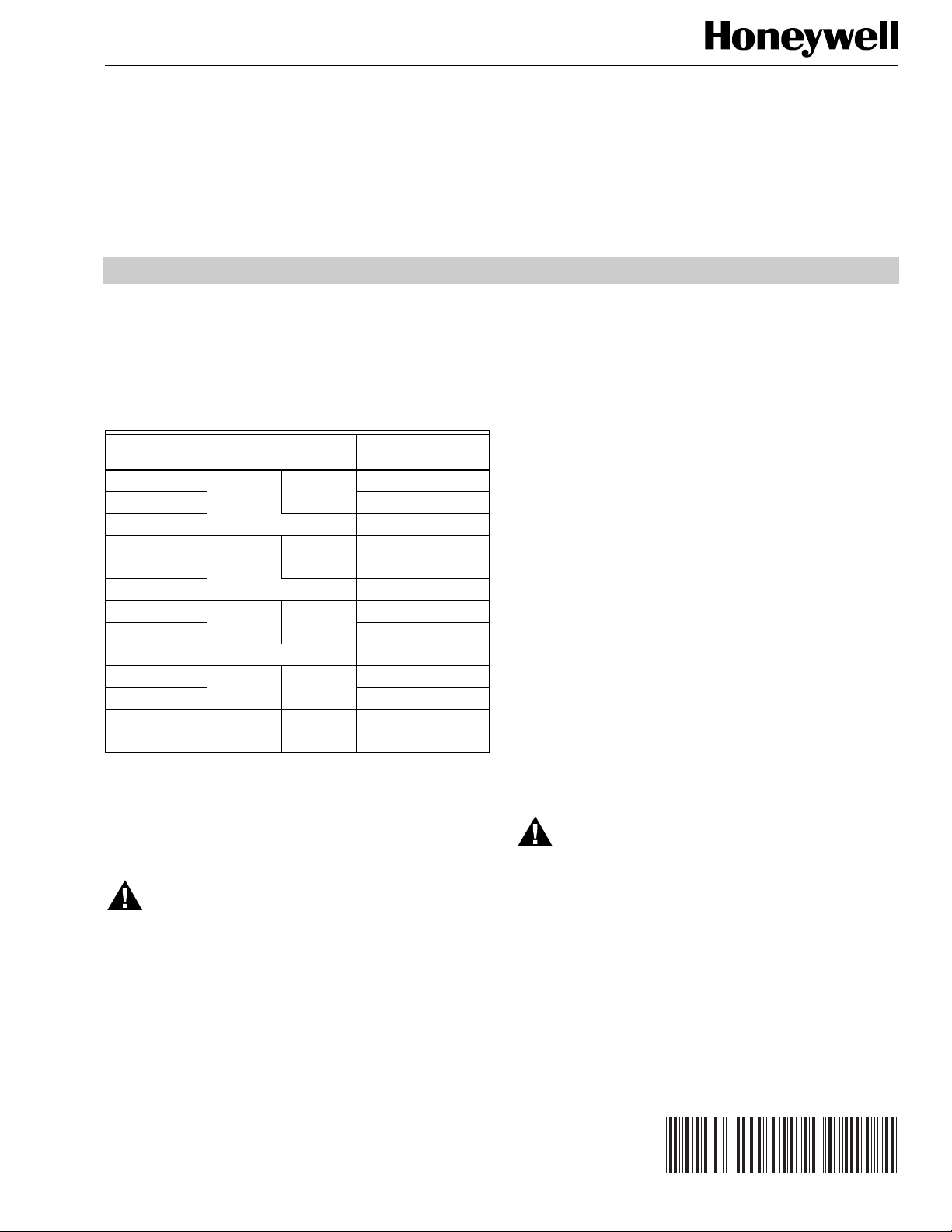
Models of the Replacement Bonnet Assembly are available
for the valves listed in Table 1.
Table 1. Replacement Bonnets for
V5055/V5097 Gas Valves.
Replacement
Bonnet
133398AA V5055A V5097A 3/4, 1, 1-1/4, 1-1/2
133417AA 2, 2-1/2, 3
136911AA (on-off) 4
133398BA V5055B V5097B 3/4, 1, 1-1/4, 1-1/2
133417BA 2, 2-1/2, 3
136911BA (Characterized Guide) 4
133398CA V5055C V5097C 3/4, 1, 1-1/4, 1-1/2
133417CA 2, 2-1/2, 3
136911CA (Proof of Closure) 4
136308AA V5055D V5097D 3/4, 1, 1-1/4, 1-1/2
136307AA 2, 2-1/2, 3
136308BA V5055E V5097E 3/4, 1, 1-1/4, 1-1/2
136307BA 2, 2-1/2, 3
Each replacement assembly contains the bonnet assembly,
two rubber seals and a tube of grease. It must be used only on
the type of valve indicated above.
Valve Valve Size (inche s)
When Installing this Product...
1. Read these instructions carefully. Failure to follow them
could damage the product or cause an unsafe condition.
2. Check the ratings given in the instructions and on the
products to make sure the products are suitable for your
application.
3. Installer must be a trained, experienced flame safeguard control technician.
4. After installation is complete, check out product
operation as provided in the instructions.
The bonnet assembly and the valve seals may be replaced
without removing the valve body from the gas line. Use the
following procedure to replace the bonnet assembly and seals
in the gas valve.
1. Turn off the gas supply at the manual shutoff valve.
2. Shut off all electrical to the valve actuator.
3. If a 7616BR Crank Arm Assembly is used with the
actuator, remove the crank arm assembly by pulling the
clip and loosening the clamp screw.
4. Disengage the arm from the actuator.
5. Remove the actuator from the valve (loosen the two set
screws).
6. Remove the valve bonnet (four bolts on the 1- to
1-1/2-inch valves, six bolts on the 2- to 3-inch valves,
eight bolts on the 4-inch valves).
7. Discard the old rubber seals.
8. Coat the new rubber seals with the grease provided and
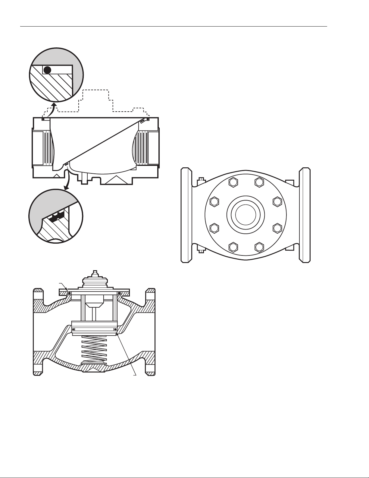
position them in the valve body as shown in Fig. 1 or 2.
(Small seal on the 4-inch valve is mounted on the
bonnet assembly.)
INSTALLATION
WARNING
Explosion Hazard.
Can cause equipment damage, serious injury or
death.
1. Only a trained experienced flame safeguard
technician should service the V5055 or V5097 Gas
Val ves.
2. Before beginning installation, turn off the gas supply
and disconnect the power supply to the valve
actuator.
3. After installation, perform a complete checkout,
including a gas leak check.
® U.S. Registered Trademark
Copyright © 2000 Honeywell Inc. • All Rights Reserved
WARNING
Explosion Hazard.
Can cause equipment damage, serious injury
or death.
Position and seat the seals in the valve body properly
to avoid a hazardous gas leak.
9. Carefully seat the new bonnet assembly on the valve
body. Make sure the seals are in the proper position.
(On the V5055/V5097 Gas Valves with a spring below
the disk, make sure the spring is centered in the
indentation on the inside of the valve body.
NOTE: The 4-inch bonnet assembly may be replaced in any
position on the valve body.
95-6981-5
Page 2
FOR V5055, V5097 GAS VALVES
10. After positioning the bonnet assembly, replace the bolts
removed in step 6.
BONNET SEAL
VALVE SEAL
NOTE: When replacing the bonnet assembly on the 4-inch
valve, draw it evenly into the valve body. Fingertighten the eight bolts. Draw the bonnet assembly
into the valve by tightening, in order, bolts 1, 5, 7 and
3 (two turns each). See Fig. 3. Repeat until the
bonnet assembly is seated. Tighten the remaining
bolts. Torque the bolts as follows:
— 3/4 in. (19 mm) to 1-1/2 in. (38 mm) valves:
55 in.-lb.
— 2 in. (51 mm) to 4 in. (102 mm) valves: 75 in.-lb.
11. Remount the actuator.
12. Securely tighten the set screws (50 to 60 inch-pounds).
13. Replace the crank arm assembly if disconnected in
step 3.
14. With the gas still off, cycle the actuator to check for
proper mechanical operation.
18
7
6
2
3
Fig. 1. Placement of valve and bonnet seals.
LARGE SEAL
SMALL SEAL
Fig. 2. Placement of valve and bonnet
seals in the four-inch valve.
M9578
M9579
45
M9582
Fig. 3. Replacement 4-inch valve bonnet assembly.
CHECKOUT
IMPORTANT
Bonnet Seal Check
After the bonnet assembly is reinstalled, turn on the gas at the
manual valve and check for gas leakage around the bonnet
seal. Paint the seal area with a rich soap and water solution.
Bubbles indicate a gas leak. If a leak is detected, check to see
that the bonnet screws are tight. If necessary, turn off the gas
again and remove the bonnet to make sure the seals are
properly seated.
Tightness of Closure Check
Instructions for testing tightness of closure of gas safety
shutoff valves on burner startup (by qualified personnel).
See Fig. 4.
Both bonnet seal and seat leak checks must be
performed after installation.
95-6981—5 2
Page 3
GAS
SUPPLY
UPSTREAM
MANUAL
GAS COCK
PRV
2 3
1/4 IN. (6 MM)
FLEXIBLE
TUBING
1/4 IN. (6 MM)
ALUMINUM OR
COPPER PILOT
TUBING
DABC E
LEAK
4
TEST
TAP
SSOV
DOWNSTREAM
MANUAL
GAS COCK
BURNER
F
MANUAL
TEST
PETCOCK
JAR OR GLASS
WITH WATER
FOR V5055, V5097 GAS VALVES
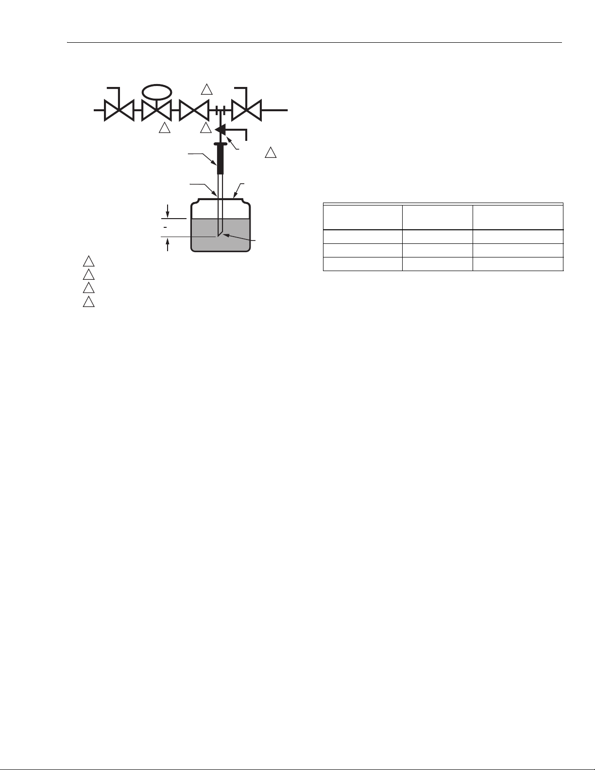
7. Program the safety shutoff valve (C) to the fully open
position (through the safety system), then immediately
de-energize the SSOV to seat the valve operationally.
8. Immerse a 1/4-inch (6 mm) tube vertically 1/2 inch
(13 mm) into a jar of water as shown in Fig. 4.
9. Slowly open the test petcock (F).
10. When the rate of the bubbles coming through the water
stabilizes, count the number of bubbles appearing
1
during a ten-second period. Each bubble appearing
during a ten-second period represents a flow rate of
approximately 0.001 cf/h. To meet U.S.A requirements,
leakage must not exceed the values given in Table 2.
Table 2. Allowable leakage (cc/hr).
1
(13 MM)
2
CUT AT
45 DEGREE
CAN ALSO BE A PERMANENT PETCOCK.
1
PRV = PRESSURE REGULATING VALVE.
2
3
SSOV = SAFETY SHUTOFF VALVE.
USE THE DOWNSTREAM TAP ON THE SS0V.
4
ANGLE
M9547F
Fig. 4. Valve leak test.
1. De-energize the control system to make sure no power
is applied to the safety shutoff valve (C).
2. Close the upstream manual gas cock (A).
3. Make sure the manual test petcock (F) in the leak test
tap assembly (D) is closed.
4. Remove the leak test tap plug and connect the test
apparatus to the leak test tap (D) as shown in Fig. 4.
5. Close the downstream manual gas cock (E).
6. Open the upstream manual gas cock (A).
Valve Size (in.)
Allowablea
Leakage (cc/hr)
Number of bubbles
per 10 seconds.
3/4, 1, 1-1/4, 1-1/2 458 16
2, 2-1/2, 3 752 26
4 1003 35
a
Based on air at standard conditions, test pressures provided
by ANSI Z21.21, section 2.4.2, and a maximum of 235 cc/h
per inch of sealoff diameter. Sealoff diameter is not to be
confused with pipe size.
NOTE: If two safety shutoff valves are used, check each
valve for tightness of closure.
11. Shut upstream manual gas cock (A).
12. Close test petcock (F), remove test apparatus, and
replace leak test tap plug (D).
13. Open upstream manual gas cock (A).
14. Open downstream manual gas cock (E).
15. Restore system to normal operation, and observe
through at least one complete cycle to assure proper
operation.
3 95-6981—5
Page 4

Automation and Control Solutions
Honeywell International Inc. Honeywell Limited-Honeywell Limitée
1985 Douglas Drive North 35 Dynamic Drive
Golden Valley, MN 55422 Scarborough, Ontario M1V 4Z9
95-6981—5 G.R. Rev. 7-00 www.honeywell.com
 Loading...