

Page 1
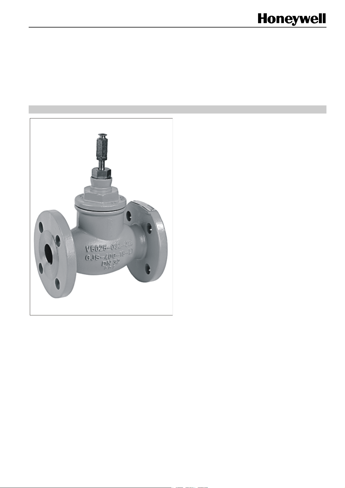
V5025A
FLANGED LINEAR VALVE PN25
SPECIFICATION DATA
FEATURES
• Pressure-balanced plug
• Nodular iron body with flanged end connections
• Low seat leakage rate
• Metal-to-metal seating for long life span
• Self-adjusting packing
• Accurate positioning to ensure state-of-the-art
temperature control
GENERAL
These single-seated valves are suitable for use in conjunction
with the modulating control of hot / chilled water or steam in
closed heating, ventilating, and air conditioning systems. They
are designed especially for use in high differential pressure
applications (e.g. district heating) and can be operated by
linear actuators ML6420/ML6425, ML7420/ML7425, or
ML6421/ML7421 or by pneumatic actuators MP953.
• Easy mounting of direct-coupled electric and
pneumatic actuators
• Approved according to DIN EN 14597 in DN15...80 in
combination with ML6425/ML7425
SPECIFICATIONS
Action Stem down to close
Nominal pressure rating PN25
Flow characteristic Equal percentage
Rangeability 50:1
Leakage rate ≤0.05% of kVS (DN15...80)
≤0.1% of k
Stroke 20 mm (DN15...80)
38 mm (DN100...150)
Valve body
End connections Flanged per ISO 7005-2
Material Nodular iron (GGG40.3)
Dimensions See Fig. 1 on page 3
Trim
Seat Stainless steel
Stem Stainless steel
Plug Stainless steel, skirt-guided
Packing Spring-loaded PTFE cone rings
Medium temperature 2...120 °C (max. 2500 kPa)
and pressure 120...160 °C (max. 2250 kPa)
160...200 °C (max. 2000 kPa)
Max. temp. differential 60 K (alternating hot/cold water)
Medium water, water-glycol (max. 50%),
steam
(DN100...150)
VS
Copyright © 2009 Honeywell Inc. • All Rights Reserved EN0B-0442GE51 R0709
Page 2
V5025A FLANGED LINEAR VALVE PN25
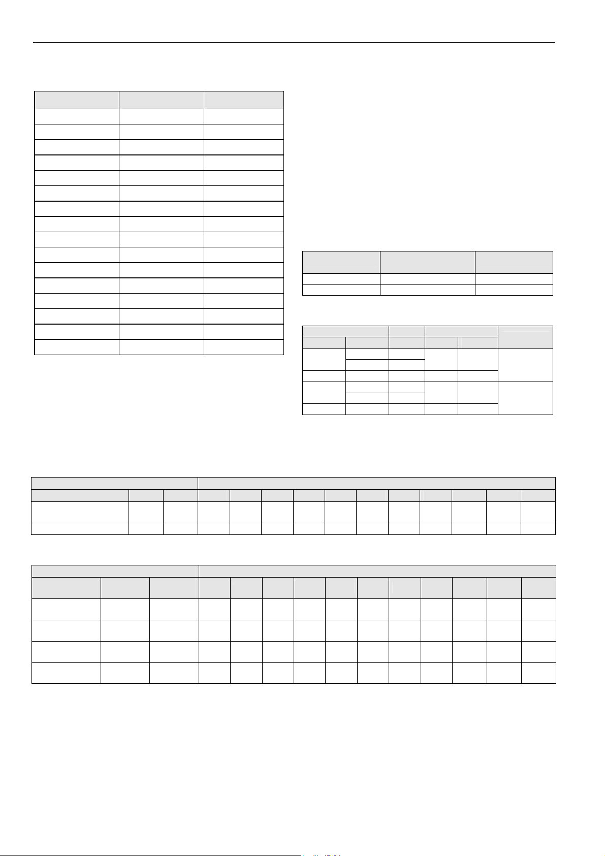
SIZES AND FLOW CAPACITIES
Order Number Valve Size kVS
V5025A1019 DN15 0.40
V5025A1027 DN15 0.63
V5025A1035 DN15 1.0
V5025A1043 DN15 1.6
V5025A1050 DN15 2.5
V5025A1068 DN15 4.0
V5025A1076 DN20 6.3
V5025A1084 DN25 10.0
V5025A1092 DN32 16.0
V5025A1100 DN40 25.0
V5025A1118 DN50 40.0
V5025A1126 DN65 63.0
V5025A1134 DN80 100.0
V5025A1142 DN100 160.0
V5025A1159 DN125 250.0
V5025A1167 DN150 360.0
CLOSE-OFF PRESSURE RATINGS (in kPa)
INSTALLATION
• Water should meet VDI 2035 requirements.
• Do not install valve with stem below the horizontal.
• Fluid flow must correspond with the arrow direction on the
valve body.
• The installation of a strainer is strongly recommended.
REPAIR PACKING KIT
Part No.: R43176755004 (DN15...80)
R43176755005 (DN100...150)
ACTUATORS
Electric Actuators
600 N (20 mm)
ML6420A ML6425A,B ML6421B
ML7420A ML7425A,B ML7421B
Pneumatic Actuators
actuator stroke acting
model size direct reverse
MP953A
MP953B 7" 20 mm X
MP953C
MP953D 7" 20 mm X
5", 8" 20 mm
13" 38 mm
5", 8" 20 mm
13" 38 mm
600 N (20 mm),
spring return
X
X
1800 N (38 mm)
positioner
yes
no
Electric Actuators
actuator valve size
model stroke force DN15 DN20 DN25 DN32 DN40 DN50 DN65 DN80 DN100 DN125 DN150
ML6420A, ML6425A,B,
ML7420A, ML7425A,B
ML6421B, ML7421B 38 mm 1800 N -- -- -- -- -- -- -- -- 2500 2500 2500
20 mm 600 N 2500 2500 2500 2500 2500 2500 2500 2500 -- -- --
Pneumatic Actuators
actuator valve size
model
MP953A,C (5")
MP953A,C (8")
MP953B,D (7")
MP953A,C (13")
spring
range
28...77 kPa
(4...11 psi)
28...77 kPa
(4...11 psi)
55...90 kPa
(8...13 psi)
28...77 kPa
(4...11 psi)
air
pressure
115 kPa 2500 2500 2500 2500 2500 1600 1200 -- -- -- --
115 kPa 2500 2500 2500 2500 2500 2500 2500 2500 -- -- --
0 kPa 2500 2500 2500 2500 2500 2500 2500 2500 -- -- --
115 kPa -- -- -- -- -- -- -- -- 2500 2500 2500
DN15 DN20 DN25 DN32 DN40 DN50 DN65 DN80 DN100 DN125 DN150
EN0B-0442GE51 R0709 2
Page 3
V5025A FLANGED LINEAR VALVE PN25
”
2
2
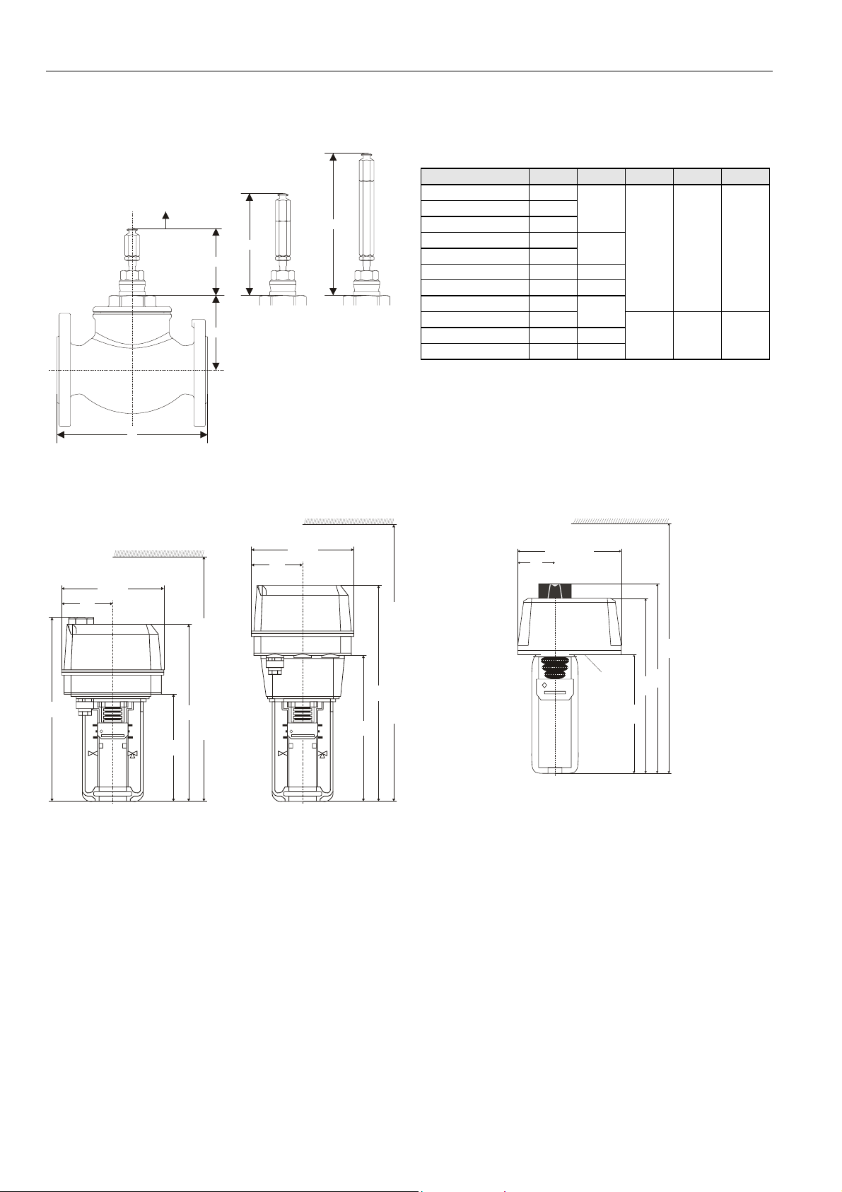
DIMENSIONS
Valve
valve size A B Y1 * Y2 * Y3 *
DN15 130
stroke
Y3
Y2
Y1*
with stem
B
A
extension for
MP953A,C 8”
*without stem extension for
ML6420/25, ML7420/25
M6421, M7421,
MP953A,C 5”, and MP953B,D 7”
with stem
extension for
MP953A,C 13
Fig. 1. V5025A with stem extensions (dimensions in mm)
Electric Actuators
DN20 150
DN25 160
DN32 180
DN40 200
DN50 230 101
DN65 290 106
DN80 310
DN100 350
DN125 400 156
DN150 480 157
* = Adjustment dimension. Valve in closed position.
95
99
150
89 133 --
133 -- 190
135x(161)
67.4
135x(161)
67.4
4
100
0 100
1000
233
322 (with High-Temperature Kit: 402 mm)
141
0
1000
192
Fig. 2. ML6420A / ML7420A and ML6425A,B / ML7425A,B
178x (178)
64
430
Two knock-outs
are provided for
cable fitting:
21.2 (PG13.5) /
284
364 (with High-Temperature Kit: 444 mm)
22.8 (PG16),
18.9 (PG11)
326
301
204
Fig. 3. ML6421B / ML7421B (dimensions in mm)
3 EN0B-0442GE51 R0709
Page 4
V5025A FLANGED LINEAR VALVE PN25
C
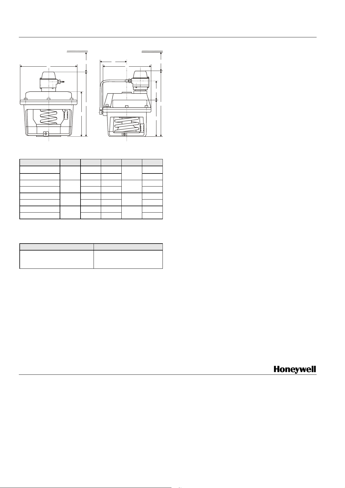
Pneumatic Actuators
E
MP953A,
0
50
100
H
F
G
E
MP953B,D
100
50
0
Fig. 4. MP953A,C / MP953B,D (dimensions in mm)
Model
MP953A, 5” 192 -- -MP953C, 5”
MP953A, 8" 237 -- -MP953C, 8"
MP953A, 13" 327 -- -MP953C, 13"
MP953B, 7" 242 -- 107
MP953D, 7"
∅E
130
210
343
180
F G H K
- 120
-- 165
-- 255
-- 137
120
140
200
120
NOTE: V5025A valves in combination with the following
actuators are approved according to DIN EN 14597:
Actuator O.S. No. DIN Registration No.
ML6425A3006
ML6425A3014
1F139/08
ML7425A6008
HK
70
F
G
--
--
--
--
Manufactured for and on behalf of the Environmental and Combustion Controls Division of Honeywell Technologies Sàrl, Rolle, Z.A. La Pièce 16, Switzerland by its Authorized Representative:
Automation and Control Solutions
Honeywell GmbH
Böblinger Strasse 17
71101 Schönaich
Germany
Phone: (49) 7031 63701
Fax: (49) 7031 637493
http://ecc.emea.honeywell.com
Subject to change without notice. Printed in Germany
EN0B-0442GE51 R0709
 Loading...