

Page 1
60-2129-4
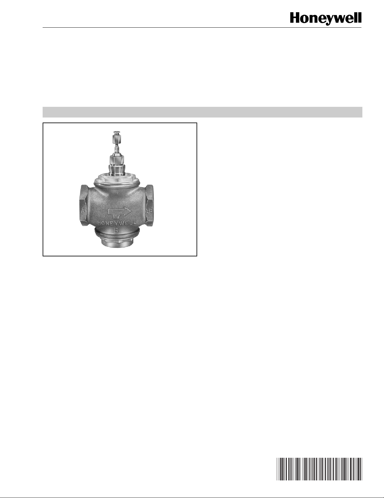
V5013B,C,F Three-Way
Mixing and Diverting Valves
PRODUCT DATA
FEATURES
• Mixing or diverting models.
•Bronze body with threaded connections or cast iron
body with flanged-end connections.
• Stainless steel stem and replaceable seats.
• Spring-loaded, self-adjusting packing.
• Constant total flow throughout full stem travel.
• Linear flow characteristic for each port, providing
constant total flow control of water or glycol solutions
(up to 50% concentration).
• Suitable for pneumatic or electric/electronic actuation.
• Repacking kits available for field servicing.
APPLICATION
The V5013 is a three-way valve for control of hot water,
cold water, and glycol solutions (up to 50% concentration)
in heating or cooling applications. These valves are used
in two-position or modulating control systems. They can
be used for mixing service (V5013B and F) to direct flow
from one of two inlets to a common outlet or for diverting
service (V5013C) to direct flow from a common inlet to
one of two outlets.
Mixing and diverting valves are not interchangeable.
Contents
Application........................................................................... 1
Features ..............................................................................1
Specifications ......................................................................2
Ordering Information ...........................................................2
Installation ...........................................................................4
Operation ............................................................................ 6
Checkout ............................................................................. 6
® U.S. Registered Trademark
Copyright © 1998 Honeywell Inc. • All Rights Reserved
Page 2

V5013B,C,F THREE-WAY MIXING AND DIVERTING VALVES
SPECIFICATIONS
Models:
See Table 1.
Dimensions:
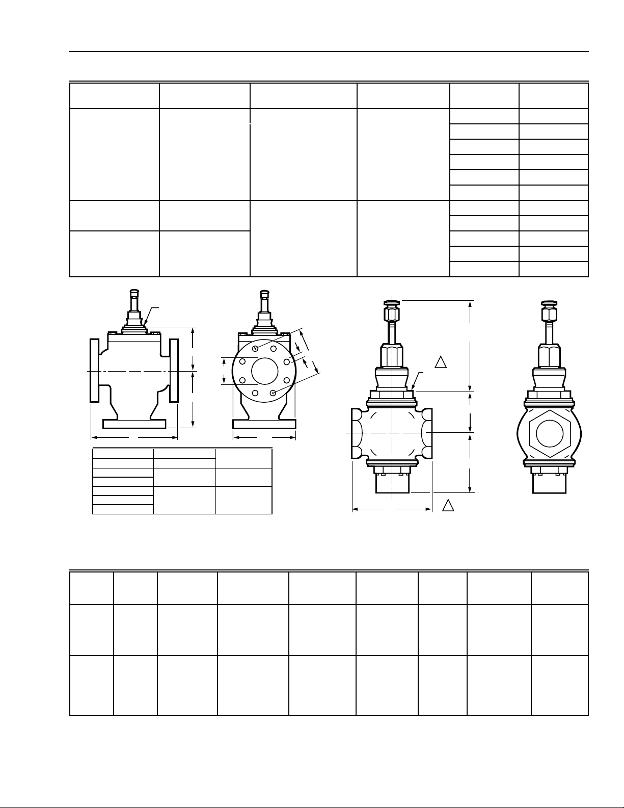
See Fig. 1 and 2 and Table 2.
Flow Characteristics:
Linear, constant total flow throughout full plug travel.
Valve Pressure-Temperature Ratings:
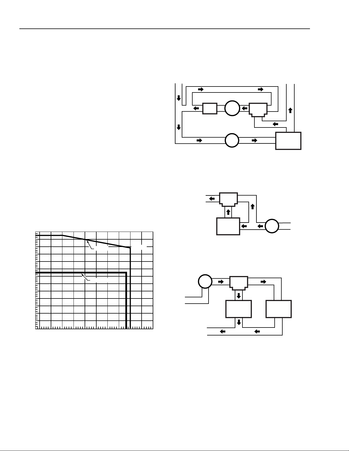
See Fig. 3.
Close-Off Ratings:
Dependent on actuator (see Valve Selection Guide,
form 68-8038).
Maximum Pressure Differential (for Normal Plug and
Seat Life):
Two-position service: 50 psi (345 kPa).
Modulating service: 25 psi (172 kPa).
Quiet Water service: 20 psi (138 kPa).
Stem Travel:
1/2- to 3-in. Valves: 3/4 in. (19 mm).
4-, 5-, and 6-in. Valves: 1-1/2 in. (38 mm).
Materials:
Body:
Threaded Valves: Bronze.
Flanged Valves: Cast iron.
Stem: Stainless steel.
Packing:
V5013B &C: Teflon cone for ANSI Class 125
flanged valves.
V5013F: Rubber or teflon/rubber for ANSI Class 150
threaded valves.
Disc and Plug:
V5013B, C: Bronze-skirted plug.
V5013F: Linear contour plug, one piece brass
construction for metal-to-metal seating.
Seat:
V5013B: Bronze, removable cage type.
V5013F: Integral brass.
Accessories:
Actuator Assemblies: See the Valve Selection Guide,
form 63-8038.
Repack Kits:
14003294-004 TRADELINE Kit for 1/2 in., 3/4 in., 1 in.
and 1-1/4 in. threaded V5013A,F Valves.
14003295-004 For 1-1/2 in., 2 in. threaded V5013A,F
and 2-1/2 in. and 3 in. flanged V5013B,C Valves.
14003296-002 For 4 in., 5 in., and 6 in. flanged
V5013B,C Valves.
14000501-001 Valve Bonnet Extension Kit. Further
separates the actuator from the valve body for high-
temperature applications.
ORDERING INFORMATION
When purchasing replacement and modernization products from your TRADELINE® wholesaler or distributor, refer to the
TRADELINE® Catalog or price sheets for complete ordering number.
If you have additional questions, need further information, or would like to comment on our products or services, please write or
phone:
1. Your local Home and Building Control Sales Office (check white pages of your phone directory).
2. Home and Building Control Customer Logistics
Honeywell Inc., 1885 Douglas Drive North
Minneapolis, Minnesota 55422-4386 (612) 951-1000
In Canada—Honeywell Limited/Honeywell Limitée, 155 Gordon Baker Road, North York, Ontario M2H 3N7.
International Sales and Service Offices in all principal cities of the world. Manufacturing in Australia, Canada, Finland, France,
Germany, Japan, Mexico, Netherlands, Spain, Taiwan, United Kingdom, U.S.A.
60-2129—4
2
Page 3
V5013B,C,F THREE-WAY MIXING AND DIVERTING VALVES
C
A
B
1
1
ACTUATOR
BASE
3-1/2 INCHES (89 MM)
WITH STEM DOWN
1-3/8 IN. (35 MM) BONNET SIZE
C7961A
Table 1. Model Descriptions and Body Specifications.
Model
Straight-through
Flow End Connections ANSI Body Class
Body
Size (in.)
Capacity
Index (Cv)
V5013F Mixing Stem Down Threaded Female NPT 150 1/2 2.5, 4.0
3/4 6.3
110
1-1/4 16
1-1/2 25
240
V5013B Mixing Stem Down Flanged 125 2-1/2 63
3 100
V5013C Diverting Stem Up 4 160
5 250
6 360
BONNET
E
A
D
F
B
C
VALVE SIZE BONNET SIZE
IN MM
2-1/2 64
376
4 102
5 125
6 152
IN. MM
1-3/8 35
1-7/8 48
NUMBER OF
BOLT HOLES
Fig. 1. V5013B,C Flanged Body Dimensions.
Table 2. V5013B,C,F Approximate Dimensions in Inches (Millimeters).
Model
V5013B,C
Fig. 1
V5013F
Fig. 2
Size in
Inches A B C D E F G
2-1/2
3
4
5
6
1/2
3/4
1
1-1/4
1-1/2
2
4-1/2 (114)
5-1/4 (133)
5-7/8 (149)
6-1/4 (159)
7-1/4 (184)
1-3/4 (44)
1-3/4 (44)
1-7/8 (48)
2 (51)
2-3/8 (60)
2-5/8 (67)
6-7/17 (164)
6-5/8 (168)
8-11/16 (221)
9-5/8 (244)
10-11/16 (271)
2-5/8 (67)
2-1/2 (64)
2-5/8 (67)
2-5/8 (67)
2-3/4 (70)
3-1/8 (79)
G
4
8
C7959A
Fig. 2. V5013F Threaded Body Dimensions.
9-1/2 (241)
11 (279)
13 (330)
15 (381)
16-1/2 (419)
3-1/2 (89)
3-3/8 (86)
3-7/8 (98)
4-1/4 (108)
4-3/4 (121)
5-7/8 (149)
2-1/2 (64)
3 (76)
4 (102)
5 (127)
6 (152)
–
–
–
–
–
–
3/4 (19)
3/4 (19)
3/4 (19)
7/8 (22)
7/8 (22)
–
–
–
–
–
–
5-1/2 (140)
6 (152)
7-1/2 (191)
8-1/2 (216)
9-1/2 (241)
–
–
–
–
–
–
7 (178)
7-1/2 (191)
9 (229)
10 (254)
11 (279)
–
–
–
–
–
–
3
60-2129—4
Page 4
V5013B,C,F THREE-WAY MIXING AND DIVERTING VALVES
INSTALLATION
When Installing this Product…
1. Read these instructions carefully. Failure to follow them
could damage the product or cause a hazardous
condition.
2. Check the ratings given in the instructions and on the
product to make sure the product is suitable for your
application.
3. Installer must be a trained, experienced service
technician.
4. After installation is complete, check out product
operation as provided in these instructions.
IMPORTANT
Location
In selecting a location, the following must be considered.
The ambient temperature must not exceed the maximum
limits for the valve or motor. Controlled liquid-pressure must
not exceed the maximum pressure limits of the valve.
Install the valve so the fluid flows in the direction of
the arrow cast on the body. Mount the valve with the
operator motor shaft horizontal.
1. Make sure sufficient space has been provided for the
complete valve assembly. The actuator assembly fits
over the valve stem.
2. The actuator assembly should not be mounted below
the valve where moisture or dirt may accumulate.
260
(1713)
240
(1655)
220
(1517)
200
(1379)
180
(1241)
160
(1103)
140
(965)
120
(827)
100
(689)
80
FLUID PRESSURE PSI (kPa)
(552)
60
(414)
40
(226)
20
(138)
0
50
(10)75(24)
100
(38)
(INCLUDES BODY AND PACKING LIMITATIONS)
V5013F
V5013 B & C
125
150
175
(52)
(66)
FLUID TEMPERATURE °F(°C)
(79)
200
(93)
(107)
225
250
(121)
217(PSI)
275
(135)
M11756
Fig. 3. Valve pressure-temperature ratings.
300
(149)
Piping Hookups
All piping must comply with local codes and ordinances. Refer
to Fig. 4-8 for typical piping hookups.
RETURN
BYPASS
V5013F OR B
M11757
COIL
PULL
PUMP
PUMP
AB
A
B
Fig. 4. Typical V5013F or B mixing valve with
constant volume through coil.
MIXED
DISCHARGE
WATER TO
HEAT LOAD
V5013F OR B
AB
A
B
BOILER
BYPASS
Fig. 5. Single zone bypass for reset control.
V5013C
RETURN
TO HEAT
LOAD
PUMP
AB
A
B
Fig. 6. V5013C diverting valve used to
change over complete system.
PUMP
SUPPLY
BOILER
M11758
BOILERCHILLER
M11759
60-2129—4
4
Page 5
V5013B,C,F THREE-WAY MIXING AND DIVERTING VALVES
VISE GRIPS HEX END NEXT TO PIPE (DO NOT TWIST OR
SQUEEZE VALVE BODY).
VISE HOLDS PIPE SECURELY AGAINST TURNING AND PARALLED
JAW WRENCH GRIPS VALVE HEX FLATS NEXT TO PIPE.
M11763
USE PROPERLY REAMED AND CLEANED PIPE AND MODERATE
AMOUNT OF DOPE (LEAVE TWO THREADS BARE).
PIPE SIZE
(INCHES)
1/2
3/4
1
1-1/4
1-1/2
2
EFFECTIVE LENGTH OF THREADS
(INCHES) [MILLIMETERS]
1/2
9/16
11/16
11/16
11/16
3/4
[12.7]
[14.3]
[17.5]
[17.5]
[17.5]
[19.1]
1
1
2
2
3
3
V5013C
SUPPLY LINE FROM
BOILER OR CHILLER
RETURN LINE TO
BOILER OR CHILLER
AB
A
B
COIL
M11760
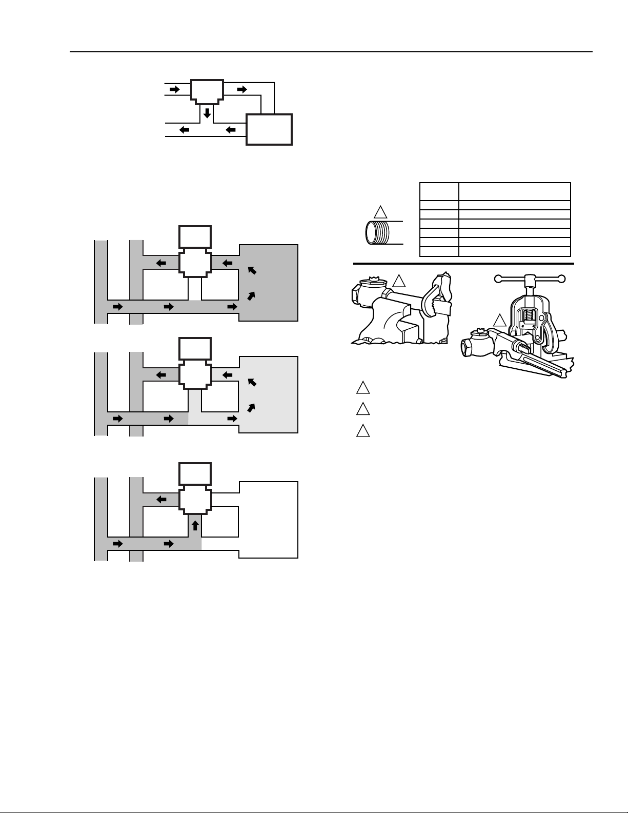
Fig. 7. Typical zone hookup of V5013C diverting valve
used to control flow through coil.
FULL
HEAT
PROPORTIONED
HEAT
AB A
B
5 GAL./MIN.
AB A
HEATING COIL
5 GPM
A
Valve Installation
Threaded Valve bodies
Line up the pipes squarely with the valve at each end. If the
pipes are forced into the valve, the body may become twisted
and improper seating will result. Prevent pipe chips, scale,
and dirt from entering the piping since they may lodge in the
seat and prevent proper closing. Apply a vise or wrench to the
valve (see Fig. 9).
2.5 GPM
B
Fig. 9. Mounting of threaded valve bodies.
Flanged Valve Bodies
SUPPLY
MAIN
NO
HEAT
RETURN
MAIN
B
2.5 GPM
5 GPM
AB A
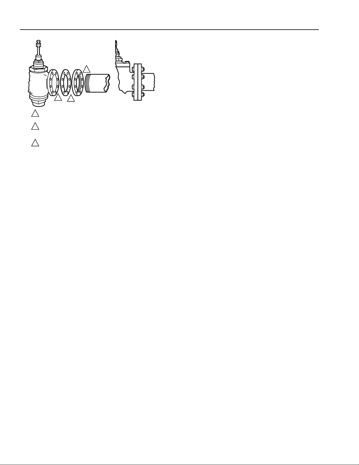
The valve flanges are flat faced with a smooth finish.
B
5 GPM
NO FLOW
THROUGH COIL
C
Companion flanges must be of the same specifications.
Mounting bolts must be long enough to allow nuts to utilize
the full length of the nut threads.
Fig. 8. Three-way mixing valve operation–coil bypass.
Three-way valves maintain constant flow in the piping.
As the temperature requirements change, the
volume of the fluid in the coil varies.
5 GPM
M11761
The bolts should be approximately 1/8 in. (3 mm) smaller than
the diameter of the bolt hole to allow clearance for installing.
To prevent leakage, use a gasket material recommended for
the medium to be handled.
5
60-2129—4
Page 6
V5013B,C,F THREE-WAY MIXING AND DIVERTING VALVES
Valves
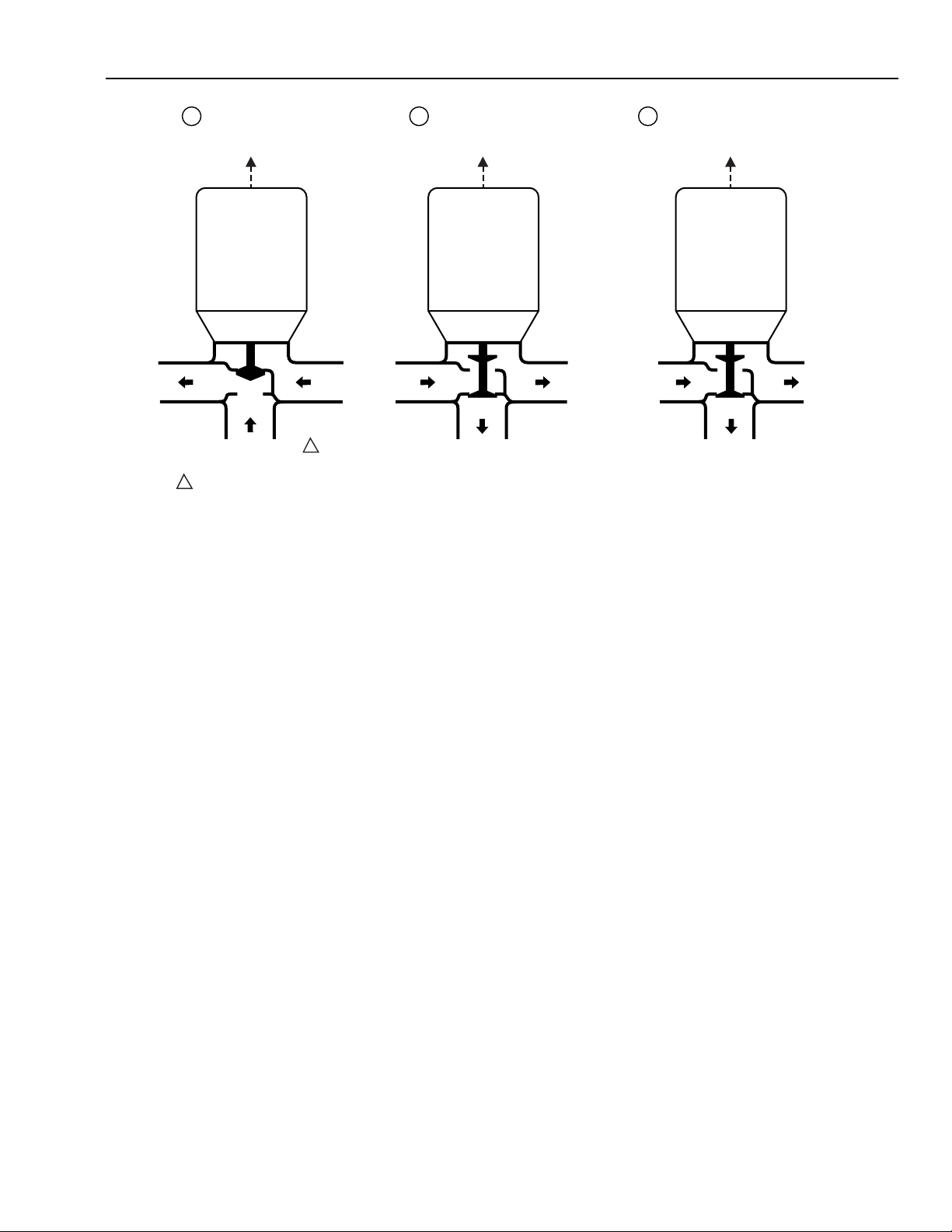
A mixing valve receives input flow at two ports, and
discharges the mixed flow at the third port. A diverting valve
receives input flow at one port, and diverts the flow to one of
3
two output ports.
IMPORTANT
V5013 Valves should not be piped backwards.
1
2
1
DO NOT APPLY PIPE DOPE TO VALVE FLANGE, COMPANION
FLANGE OR GASKET.
BE SURE FACE OF COMPANION FLANGE IS FLUSH WITH FACE
2
OF VALVE-BODY FLANGE AND ALIGNED SQUARELY BEFORE
TIGHTENING MOUNTING NUTS.
IF POSSIBLE, MOUNT COMPANION FLANGE ON PIPE BEFORE
3
MOUNTING FLANGE ON THE VALVE.
M11764
Fig. 10. Mounting of flanged valve bodies.
NOTE: For V5013F and B, if the pressures in the pipe lines
at inlets A and B are unequal, a balancing cock may
be installed in the line carrying the higher pressure.
Best possible modulation will be obtained if this cock
is adjusted under actual operating conditions so that
pressures A and B are equal at midstroke.
OPERATION
Mixing and Diverting
It is important to understand the differences between mixing
valves (V5013B,F) and diverting valves (V5013C). When
applied to valves, the terms
always carry the same connotation as when applied to
applications. Namely, a
use a
mixing valve
. The type of valve used is dependent upon
the piping of the application.
mixing
and
diverting
mixing application
do not
does not always
Applications
The terms
always clearly define the appropriate V5013. The proper
V5013 depends on the valve piping. One example of this is
the coil bypass application (see Fig. 7 and 8). A diverting
valve installed upstream of the coil determines the flow
through the coil (see Fig. 7). This is functionally the same as a
mixing valve installed downstream of the coil directing water
from either the coil or the bypass to the return piping (see Fig.
8). Almost all new installations can use a V5013B,F Mixing
Valve, given an appropriate mixing valve piping arrangement.
diverting application
and
mixing application
do not
CHECKOUT
It is important to check the valve stem to see that it operates
freely. Impaired valve stem operation may indicate that the
body was twisted by faulty piping or the stem was bent by
rough handling. Either of these conditions may warrant
replacement of the valve body or other components.
The valve should be checked at regular intervals for leakage
around the packing. The packing is spring-loaded and should
seldom require attention. If leakage is discovered and
inspection shows that the packing gland is screwed down
tightly, the valve must be repacked.
60-2129—4
6
Page 7
V5013B,C,F THREE-WAY MIXING AND DIVERTING VALVES
TO RETURN
LINE
V5013F OR B USED IN
A
HEATING APPLICATION
TO CONTROLLER TO CONTROLLER TO CONTROLLER
AB
OUT
SUPPLY LINE FROM
HOT WATER BOILER
1
ALSO PIPED TO COIL INLET.
A
FROM
IN
COIL
B IN B OUT B OUT
1
SUPPLY
V5013C USED IN
B C
HEATING APPLICATION
AB
IN
TO COIL
BYPASS
A
OUT
TO
COIL
RETURN
LINE
FROM LOAD
V5013C USED AS SYSTEM
AUTO CHANGEOVER
Fig. 11. V5013B,C,F valve hookups.
AB
IN
TO CHILLER
A
OUT
TO
BOILER
M11762
7
60-2129—4
Page 8

V5013B,C,F THREE-WAY MIXING AND DIVERTING VALVES
Home and Building Control
Honeywell Inc.
Honeywell Plaza
P.O. Box 524
Minneapolis MN 55408-0524
Honeywell Latin American Region
480 Sawgrass Corporate Parkway
Suite 200
Sunrise FL 33325
60-2129—4 B.B. Rev. 2-98
60-2129—4
Home and Building Control
Honeywell Limited-Honeywell Limitée
155 Gordon Baker Road
North York, Ontario
M2H 3N7
Honeywell Europe S.A.
3 Avenue du Bourget
1140 Brussels
Belgium
Printed in U.S.A. on recycled
paper containing at least 10%
post-consumer paper fibers.
8
Honeywell Asia Pacific Inc.
Room 3213-3225
Sun Hung Kai Centre
No. 30 Harbour Road
Wanchai
Hong Kong
www.honeywell.com
 Loading...