

Page 1

Kombi-3-plus BLACK (V5100)
Kombi-3-plus RED (V5000)
V5000, V5010, V5100
Kombi-3-plus
BALANCING AND SHUTOFF VALVES
PRODUCT DATA
CONTENTS
Design...................................................................................2
Materials................................................................................2
Application............................................................................2
Features................................................................................2
Specifications.......................................................................2
Dimensions...........................................................................3
Kombi-3-plus BLACK (V5100) ....................................3
Kombi-3-plus RED (V5000) ........................................3
Kombi-3-plus BLUE (V5010).......................................4
Ordering Information...........................................................5
Accessories..........................................................................5
Connections................................................................5
Accessories.................................................................6
Measuring equipment ................................................. 6
Installation Examples ..........................................................7
Flow Data Kombi-3-plus RED (V5000)................................8
Flow Data Kombi-3-plus RED (V5000) with Measuring
Adapter..................................................................................9
Flow Data Kombi-3-plus BLACK (V5100).........................10
Flow Data Kombi-3-plus BLUE (V5010), DN10.................11
Flow Data Kombi-3-plus BLUE (V5010), DN15.................12
Flow Data Kombi-3-plus BLUE (V5010), DN20.................13
Flow Data Kombi-3-plus BLUE (V5010), DN25.................14
Flow Data Kombi-3-plus BLUE (V5010), DN32.................15
Flow Data Kombi-3-plus BLUE (V5010), DN40.................16
Flow Data Kombi-3-plus BLUE (V5010), DN50.................17
Flow Data Kombi-3-plus BLUE (V5010), DN65.................18
Flow Data Kombi-3-plus BLUE (V5010), DN80.................19
Influence of Coolants on Flow Values..............................20
Correction Factor f .................................................... 20
Kombi-3-plus BLUE (V5010)
Copyright © 2002 Honeywell AG • All rights reserved EN0H-0046GE25 R0402
Page 2

KOMBI-3-PLUS (V5000, V5010, V5100)
Design
•
Valve body DN10 to DN20 with internal threads to
DIN2999 (ISO7) for threaded pipe or copper and precision
steel pipe 10...20 mm (see Accessories), or
•
Valve body DN25 to DN80 with internal threads to
DIN2999 (ISO7) for threaded pipe, or
•
Valve body DN10 to DN50 with external threads to ISO228
for use with connections (see Accessories)
•
Valve insert with handwheel
•
Pre-setting dial and display (Kombi-3-plus BLUE only)
Materials
•
Valve housing made of red bronze
•
Valve insert made of brass with seat sealing made of
PTFE
•
O-rings and soft seals made of EPDM
•
Handwheel, pre-setting dial and display made of plastic,
black, red or blue and white
•
Connection nuts made of brass
Application
The hydronic balance is a significant requirement for the
efficient operation of a hydronic heating or cooling installation.
In an unbalanced system under or over provision of hot water
to individual radiators or circuits can occur. Apart from the
correct selection of radiator valves, regulation of individual
circuits is also necessary and in some cases, such as in
DIN 18 380, VOB part C, is required by national standards.
This requirement is met with Kombi-3-plus shutoff and balancing valves.
Kombi-3-plus BLACK for the supply has the functions shutoff, draining and filling (draining adapter required).
Kombi-3-plus RED for the supply additionally supports measuring of the flow and differential pressure.
Kombi-3-plus BLUE for the return has the functions shutoff,
draining and filling, pre-setting – together with a KombiDiaphragm Unit and a suitable valve in the supply Kombi-3plus BLUE can be converted into an automatic balancing
valve – even after the system has been taken into commission.
Features
• All functions of the Kombi-3-plus valves can be in-
stalled through the spindle
• Kombi-3-plus BLUE DN10 to DN40 can be retrofitted
with a Kombi-Diaphragm Unit – without interrupting
operation of the system
• Combination of Kombi-3-plus RED and BLUE allows
measuring in the supply and pre-setting in the return –
at the same time.
• High accuracy of pre-setting because of individual
adjustment
• Robust valve body made of corrosion resistant red
bronze
• Availabe in sizes up to DN80
• Visible pre-setting dial with concealed pre-setting
wheel (Kombi-3-plus BLUE)
• Maintenance free spindle with double O-ring sealings
• PTFE seat sealing
Specifications
Medium
Operating temperature
Operating pressure
Differential pressure
vs
(cv)-values
k
NOTE: Differential pressure: Closing pressure for
Kombi-3-plus BLUE with installed Kombi-Diaphragm
Unit. Regarding noise generation the conditions, requirements and installation design have to be taken
into account.
Water, water-glycol mixture
2...130°C (36...266°F)
max. 16 bar (232 psi)
max. 2,0 bar (29 psi) see NOTE below
see tables on pages 3 and 4 or
flow diagrams
EN0H-0046GE25 R0402 2 Honeywell AG • All rights reserved
Page 3
Dimensions
KOMBI-3-PLUS (V5000, V5010, V5100)
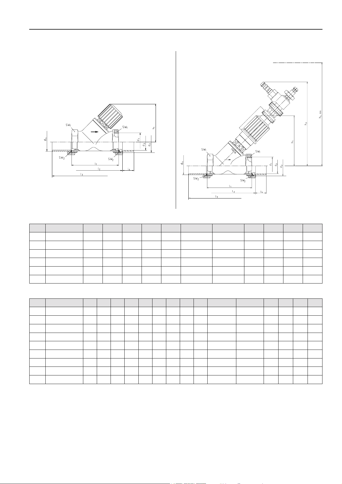
Kombi-3-plus BLACK (V5100)
Fig. 1. Kombi-3-plus BLACK
DN kvs (cv)-value h
10
15
20
25
32
40
2,5 (2,93) 60 60 74 110 10
2,5 (2,93) 65 65 81 125 12
7,0 (8,19) 70 75 92 146 17
7,0 (8,19) 72 90 108 170 20
22,0 (25,7) 120 110 128 200 25
22,0 (25,7) 120 120 140 220 29
1
Kombi-3-plus RED (V5000)
Table 1. Dimensions Kombi-3-plus BLACK
1
l
2
l
3
l
4
l
1
d
Rp3/8”
Rp1/2”
Rp3/4”
Rp1”
Rp1 1/4”
Rp1 1/2”
Fig. 2. Kombi-3-plus RED
2
d
3
d
4
d
SW1SW
G5/8”A 12 16 22 27
G3/4”A 15 20,5 27 30
G1”A 22 26 32 37
G1 1/4”A 28 33 41 47
G1 1/2”A 35 41 50 52
G1 3/4”A 42 47,5 55 60
2
Table 2. Dimensions Kombi-3-plus RED
DN kvs (cv)-value h1h3h4h5h
10
15
20
25
32
40
50
65
80
1,5 (1,76) 85 145 195 135 130 60 74 110 10
2,5 (2,93) 85 145 195 135 130 65 81 125 12
4,5 (5,27) 100 160 210 150 145 75 92 146 17
6,5 (7,61) 100 160 210 150 145 90 108 170 20
13,0 (15,2) 137 195 280 185 210 110 128 200 25
20,0 (23,4) 137 195 280 185 210 120 140 220 29
35,0 (41,0) 158 215 300 205 230 150 170 260 34
42,0 (49,1) 195 225 310 215 - 180 - - -
68,0 (79,6) 210 240 325 230 - 200 - - -
6l1
2
3
l
4
l
l
1
d
Rp3/8”
Rp1/2”
Rp3/4”
Rp1”
Rp1 1/4”
Rp1 1/2”
Rp2”
Rp2 1/2”
Rp3”
2
d
3
d
d4SW1SW
G5/8”A 12 16 22 27
G3/4”A 15 20,5 27 30
G1”A 22 26 32 37
G1 1/4”A 28 33 41 47
G1 1/2”A 35 41 50 52
G1 3/4”A 42 47,5 55 60
G2 3/8”A 54 60 70 75
---85-
- - - 100 -
NOTE: All dimensions in mm if not stated otherwise.
Honeywell AG • All rights reserved 3 EN0H-0046GE25 R0402
2
Page 4
KOMBI-3-PLUS (V5000, V5010, V5100)
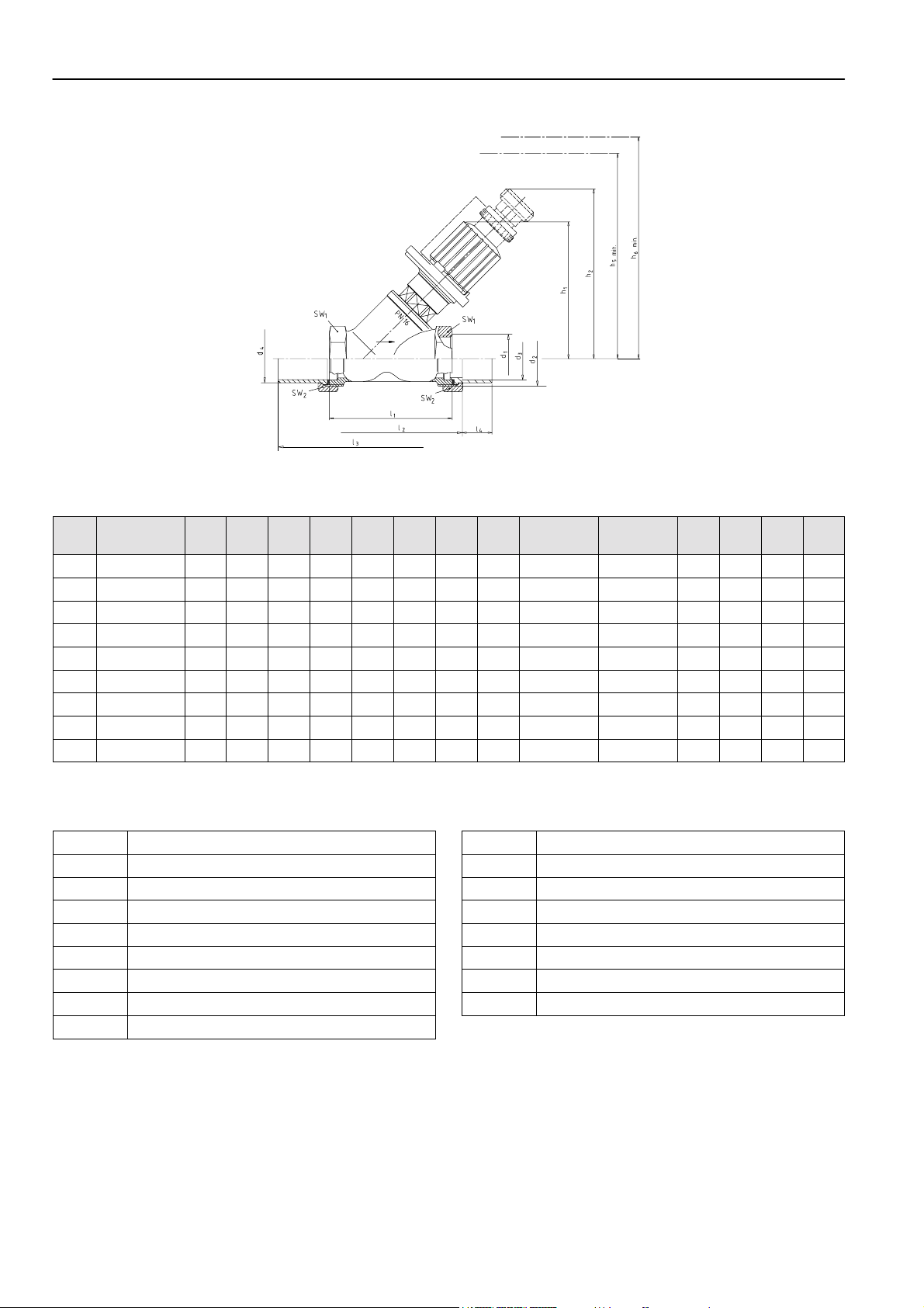
Kombi-3-plus BLUE (V5010)
Table 3. Dimensions Kombi-3-plus BLUE
DN k
vs
(cv)-
value
10
2,4 (2,81) 85 105 135 130 60 74 110 10
15
2,7 (3,16) 85 105 135 130 65 81 125 12
20
6,4 (7,49) 100 120 150 145 75 92 146 17
25
6,8 (7,96) 100 120 150 145 90 108 170 20
32
21,0 (24,6) 137 155 185 210 110 128 200 25
40
22,0 (25,7) 137 155 185 210 120 140 220 29
50
38,0 (44,5) 158 176 205 230 150 170 260 34
65
47,7 (55,8) 195 186 215 - 180 - - -
80
71,0 (83,1) 210 201 230 - 200 - - -
1
2
h
h
5
h
Fig. 3. Kombi-3-plus BLUE
6
1
2
h
l
3
l
l
4
l
1
d
Rp3/8”
Rp1/2”
Rp3/4”
Rp1”
Rp1 1/4”
Rp1 1/2”
Rp2”
Rp2 1/2”
Rp3”
2
d
3
d
d4SW1SW
G5/8”A 12 16 22 27
G3/4”A 15 20,5 27 30
G1”A 22 26 32 37
G1 1/4”A 28 33 41 47
G1 1/2”A 35 41 50 52
G1 3/4”A 42 47,5 55 60
G2 3/8”A 54 60 70 75
---85-
- - - 100 -
2
NOTE: All dimensions in mm if not stated otherwise.
Table 4. Abbreviations used for dimensions
DN
d
d
d
d
h
h
h
h
EN0H-0046GE25 R0402 4 Honeywell AG • All rights reserved
Nominal size
1
Internal thread on body (connection size)
2
External thread on body
3
Inner Ø of connection
4
Outer Ø of connection
1
Height with valve fully open
2
Height with installed draining adapter
3
Height with installed measuring adapter
4
Clearance required to fit measuring adapter
h
h
l
l
l
l
SW
SW
5
Clearance required to fit draining adapter
6
Clearance required to fit tamper-proof cap
1
Body length according to DIN3502
2
Installed length with soldering connections
3
Installed length with welding connections
4
Length of pipe penetration
1
Wrench size
2
Wrench size
Page 5
KOMBI-3-PLUS (V5000, V5010, V5100)
Ordering Information
Complete OS-No. with desired dimension, e.g. ‘V5000X’ in DN25 has OS-No. ‘V5000X0025’
Type OS-No. DN 10 15 20 25 32 40 50 65 80
Rp 3/8” 1/2” 3/4” 1” 1 1/4” 1 1/2” 2” 2 1/2” 3”
Kombi-3-plus BLACK,
internal threads
Kombi-3-plus BLACK,
external threads
Kombi-3-plus RED,
internal threads
Kombi-3-plus RED,
external threads
Kombi-3-plus BLUE,
internal threads
Kombi-3-plus BLUE,
external threads
V5100Y 0010 0015 0020 0025 0032 0040 — — —
V5100X 0010 0015 0020 0025 0032 0040 — — —
V5000Y 0010 0015 0020 0025 0032 0040 0050 0065 0080
V5000X 0010 0015 0020 0025 0032 0040 0050 — —
V5010Y 0010 0015 0020 0025 0032 0040 0050 0065 0080
V5010X 0010 0015 0020 0025 0032 0040 0050 — —
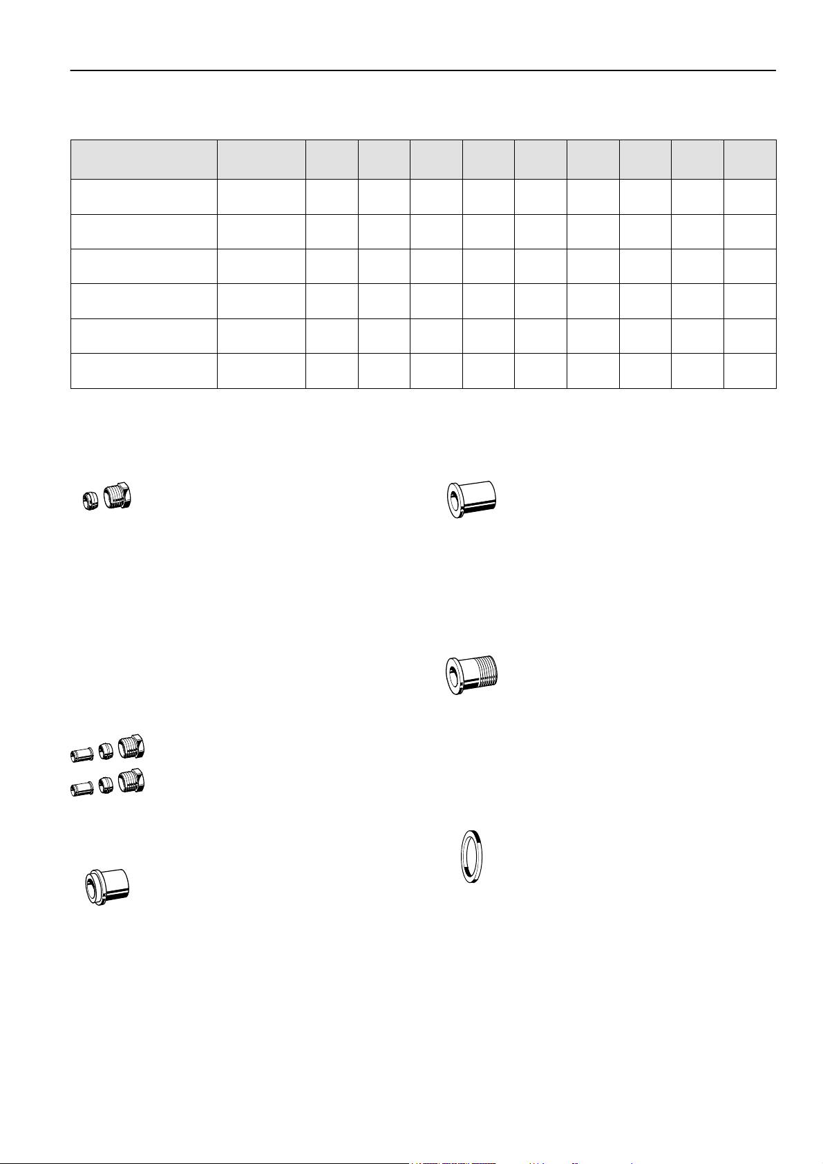
Accessories
Connections
Set of compression ring and nut
3/8” x 10 mm VA650A1010
3/8” x 12 mm VA650A1012
1/2” x 10 mm VA650A1210
1/2” x 12 mm VA650A1212
1/2” x 14 mm VA650A1214
1/2” x 15 mm VA650A1215
1/2” x 16 mm VA650A1216
3/4” x 18 mm VA650A2018
3/4” x 22 mm VA650A2022
NOTE: Support inserts have to be used for soft copper and
steel pipe (wall thickness 1 mm).
Set of compression ring, nut and support insert (2 pcs each)
3/8” x 12 mm VA651A1012
1/2” x 12 mm VA651A1212
1/2” x 15 mm VA651A1215
1/2” x 16 mm VA651A1216
3/4” x 18 mm VA651A2018
Soldering connection made of brass
12 mm, for valves DN10 VA5530A010
15 mm, for valves DN15 VA5530A015
22 mm, for valves DN20 VA5530A020
28 mm, for valves DN25 VA5530A025
35 mm, for valves DN32 VA5530A032
42 mm, for valves DN40 VA5530A040
54 mm, for valves DN50 VA5530A050
Welding connection made of steel
for valves DN10 VA5540A010
for valves DN15 VA5540A015
for valves DN20 VA5540A020
for valves DN25 VA5540A025
for valves DN32 VA5540A032
for valves DN40 VA5540A040
for valves DN50 VA5540A050
Externally threaded connection made of brass
3/8”, for valves DN10 VA5500A010
1/2”, for valves DN15 VA5500A015
3/4”, for valves DN20 VA5500A020
1”, for valves DN25 VA5500A025
1 1/4”, for valves DN32 VA5500A032
1 1/2”, for valves DN40 VA5500A040
2”, for valves DN50 VA5500A050
Sealing ring
3/8”, for valves DN10 VA5090A010
1/2”, for valves DN15 VA5090A015
3/4”, for valves DN20 VA5090A020
1”, for valves DN25 VA5090A025
1 1/4”, for valves DN32 VA5090A032
1 1/2”, for valves DN40 VA5090A040
2”, for valves DN50 VA5090A050
Honeywell AG • All rights reserved 5 EN0H-0046GE25 R0402
Page 6
KOMBI-3-PLUS (V5000, V5010, V5100)
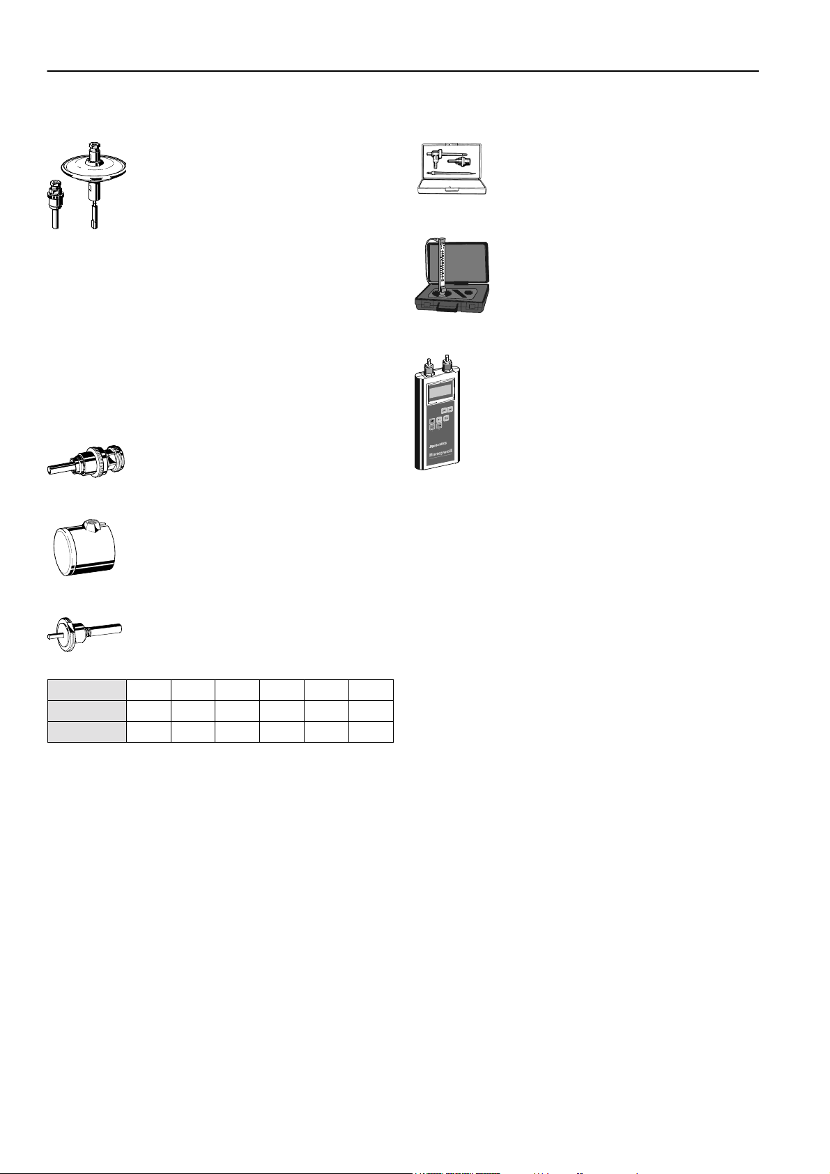
Accessories
Kombi-Diaphragm Unit
Setting range 0,1...0,3 bar
(1,45...4,35 psi) differential
pressure;
for Kombi-3-plus BLUE
DN10...DN40
Setting range 0,3...0,6 bar
(4,35...8,7 psi) differential
pressure;
for Kombi-3-plus BLUE
DN10...DN40
NOTE: For product information and diagrams see product
data sheet ‘Kombi-DU Diaphragm Unit’.
The Kombi-3-plus BLUE valve must be pre-set to 1.5
(for DN10...25) or 1.0 (DN32...40) when used with
the Kombi-DU Diaphragm Unit.
Pump pressure: max. 2 bar (29 psi)
Draining adapter
for all types and sizes VA3500A001
Tamper-proof cap
for valves DN15...DN25 VA2501A010
for valves DN32...DN50 VA2501A032
V5012A0103
V5012A0306
Measuring equipment
Pressure measuring set
for all Kombi-3-plus RED VA3502A001
Flow meter
for all Kombi-3-plus RED VM200A1001
‘BasicMES’ handheld measuring computer
for all Kombi-3-plus RED;
computer is supplied with
case and accessories
VM241A1002
Adapter for actuators with M30 x 1,5 connection
for Kombi-3-plus BLUE
DN10...DN40
Flow values for Kombi-3-plus BLUE with installed adapter:
DN
kvs-value
cv-value
NOTE: The Kombi-3-plus BLUE valve must be pre-set to 1.5
(for DN10...25) or 1.0 (DN32...40) when used with
actuator.
Actuator adapter can only be used with DN10 valve
housings with ‘H’ marking (valve housings since
10/1999).
Pump pressure: max. 2 bar (29 psi)
10 15 20 25 32 40
1,50 1,50 3,50 3,50 5,50 5,50
1,76 1,76 4,10 4,10 6,44 6,44
VA2500A001
EN0H-0046GE25 R0402 6 Honeywell AG • All rights reserved
Page 7

Installation Examples
KOMBI-3-PLUS (V5000, V5010, V5100)
Fig. 4. Kombi-3-plus RED and BLUE in risers
Fig. 5. Zone control with Kombi-3-plus and an actuator
Fig. 6. Kombi-3-plus in a distribution manifold
Fig. 7. Kombi-3-plus in an air heater/fan coil unit
Honeywell AG • All rights reserved 7 EN0H-0046GE25 R0402
Page 8

KOMBI-3-PLUS (V5000, V5010, V5100)
C
Flow Data Kombi-3-plus RED (V5000)
DN 10 DN 25 DN 40 65 80
onnection size
DN 20 DN 32 DN 50DN 15
0
0
1
7
,
8
6
8
5
7
0
,
6
4
0
,
5
3
0
,
4
0
,
3
2
0
,
2
0
0
0
0
1
9
8
0
,
7
1
6
100
Flow
3 2 4 5 6 7 8 100009324563
2 4 5 6 7 8 1000
kg/h
0,1
DN
kvs-value
cv-value
10 15 20 25 32 40 50 65 80
1,50 2,50 4,50 6,50 13,0 20,0 35,0 42,0 68,0
1,76 2,93 5,27 7,61 15,2 23,4 41,0 49,1 80,0
5
4
5
,
0
3
3
,
0
2
r
a
b
m
0
1
9
0,25 0,50,028
1,0
2,5
5,0l/sec
10,0
.
I
p
.
o
S
r
a
.
d
P
P
e
r
u
s
5
0
s
4
0
e
1
r
,
0
0
1
P
EN0H-0046GE25 R0402 8 Honeywell AG • All rights reserved
Page 9

Flow Data Kombi-3-plus RED (V5000) with Measuring Adapter
C
onnection size
DN 10 DN 25 DN 40 65 80
DN 20 DN 32 DN 50DN 15
KOMBI-3-PLUS (V5000, V5010, V5100)
6
5
4
3
2
0
0
0
0
0
0
1
1
9
8
7
6
7
,
8
8
7
0
,
6
0
,
5
0
,
4
0
,
3
0
,
2
0
,
1
100
Flow
3 2 4 5 6 7 8 100009324563
2 4 5 6 7 8 1000
kg/h
0,1
DN
kvs-value
cv-value
10 15 20 25 32 40 50 65 80
1,55 2,65 4,88 7,30 14,5 23,0 41,0 53,0 68,0
1,81 3,10 5,71 8,54 17,0 26,9 48,0 62,0 80,0
5
4
5
,
0
r
e
t
p
a
3
d
a
g
n
i
r
u
s
3
a
,
e
0
m
2
t
a
e
r
u
s
s
r
a
b
m
0
1
9
0,25 0,50,028
1,0
2,5
5,0l/sec
10,0
.
e
I
r
.
p
S
a
.
l
P
P
a
i
t
n
e
r
5
0
e
4
f
0
f
1
i
,
0
0
1
D
Honeywell AG • All rights reserved 9 EN0H-0046GE25 R0402
Page 10

KOMBI-3-PLUS (V5000, V5010, V5100)
Flow Data Kombi-3-plus BLACK (V5100)
DN
kvs-value
cv-value
EN0H-0046GE25 R0402 10 Honeywell AG • All rights reserved
10 15 20 25 32 40
2,50 2,50 7,00 7,00 22,0 22,0
2,93 2,93 8,19 8,19 25,7 25,7
Page 11

Flow Data Kombi-3-plus BLUE (V5010), DN10
P
0,3
0,6
KOMBI-3-PLUS (V5000, V5010, V5100)
re-setting
0,8
1,5 2
2,5
31
3,5
4
4,9
7
,
8
6
8
5
7
0
,
6
4
0
,
5
3
0
,
4
0
,
3
2
0
,
2
0
0
0
0
0
0
1
1
9
8
0
,
7
1
6
10
Flow
Pre-setting
kv-value
cv-value
5
4
3
2
r
p
a
o
b
r
a
d
P
m
e
r
u
s
0
s
0
e
r
0
0
P
1
1
4kg/h
2
356781009 2 4 5 6 7 8 1000932
0,025
0,050,0028 0,01 0,5l/sec
0,1
0,25
3
0,3 0,4 0,6 0,8 1,0 1,2 1,4 1,6 1,8 2,0 2,2 2,4 2,6 2,8 3,0 3,2 3,4 3,6
0,37 0,43 0,49 0,57 0,65 0,73 0,81 0,88 0,94 1,00 1,05 1,10 1,16 1,22 1,30 1,39 1,50 1,63
0,43 0,50 0,57 0,67 0,76 0,85 0,95 1,03 1,10 1,17 1,23 1,29 1,36 1,43 1,52 1,63 1,76 1,91
5
,
0
3
,
0
.
I
.
S
.
P
5
4
1
,
0
Pre-setting
kv-value
cv-value
3,8 4,0 4,2 4,4 4,6 4,8 4,9 = open
1,77 1,92 2,07 2,21 2,32 2,39 kvs = 2,40
2,07 2,25 2,42 2,59 2,71 2,80 2,81
NOTE: Flow diagram is ONLY valid for valve WITHOUT installed actuator (-adapter) or Kombi-Diaphragm Unit
Honeywell AG • All rights reserved 11 EN0H-0046GE25 R0402
Page 12
KOMBI-3-PLUS (V5000, V5010, V5100)
P
Flow Data Kombi-3-plus BLUE (V5010), DN15
0,3
0,6
0,8
re-setting
1,5 2
2,5
7
3,5
4
4,9
0
0
1
31
,
8
6
8
5
7
0
,
6
4
0
,
5
3
0
,
4
0
,
3
2
0
,
2
0
0
0
0
1
9
8
0
,
7
1
6
10
Flow
Pre-setting
kv-value
cv-value
5
4
3
2
r
p
a
o
b
r
a
d
P
m
e
r
u
s
0
s
0
e
r
0
0
P
1
1
4kg/h
2
356781009 2 4 5 6 7 8 1000932
0,025
0,050,0028 0,01 0,5l/sec
0,1
0,25
3
0,3 0,4 0,6 0,8 1,0 1,2 1,4 1,6 1,8 2,0 2,2 2,4 2,6 2,8 3,0 3,2 3,4 3,6
0,37 0,43 0,49 0,57 0,65 0,73 0,81 0,88 0,94 1,00 1,05 1,10 1,16 1,22 1,32 1,42 1,57 1,74
0,43 0,50 0,57 0,67 0,76 0,85 0,95 1,03 1,10 1,17 1,23 1,29 1,36 1,43 1,54 1,66 1,84 2,04
5
,
0
3
,
0
.
I
.
S
.
P
5
4
1
,
0
Pre-setting
kv-value
cv-value
3,8 4,0 4,2 4,4 4,6 4,8 4,9 = open
1,92 2,12 2,31 2,49 2,63 2,67 kvs = 2,70
2,25 2,48 2,70 2,91 3,08 3,12 3,16
NOTE: Flow diagram is ONLY valid for valve WITHOUT installed actuator (-adapter) or Kombi-Diaphragm Unit
EN0H-0046GE25 R0402 12 Honeywell AG • All rights reserved
Page 13

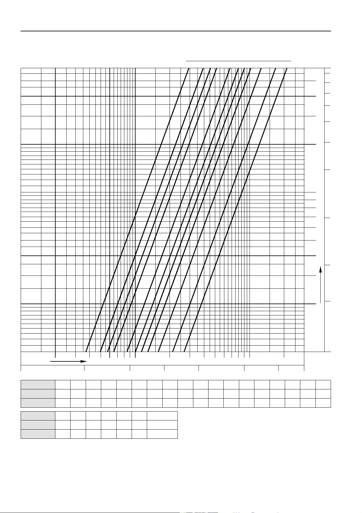
Flow Data Kombi-3-plus BLUE (V5010), DN20
P
0,3
0,6
0,8
KOMBI-3-PLUS (V5000, V5010, V5100)
re-setting
1,5
1
2,5 3
2
3,5
4
51,2 5,9
0
0
1
7
,
8
6
8
5
7
0
,
6
4
0
,
5
3
0
,
4
0
,
3
2
0
,
2
0
0
0
0
1
9
8
0
,
7
1
6
60 100
kg/h
Flow
l/sec
Pre-setting
kv-value
cv-value
5
4
3
2
r
p
a
o
b
r
a
d
m
P
e
r
u
s
0
s
0
e
r
0
0
1
1
P
2 4 5 6 7 8 100093 2 4 5 6 7 8 1000093
0,05
0,10,017
0,25
0,5
1,0
2,5
0,3 0,4 0,6 0,8 1,0 1,2 1,4 1,6 1,8 2,0 2,2 2,4 2,6 2,8 3,0 3,2 3,4 3,6
0,68 0,72 0,84 0,97 1,10 1,30 1,50 1,70 1,90 2,10 2,30 2,50 2,70 2,91 3,12 3,36 3,60 3,86
0,80 0,84 0,98 1,13 1,29 1,52 1,76 1,99 2,22 2,46 2,69 2,93 3,16 3,40 3,65 3,93 4,21 4,52
5
,
0
3
,
0
.
I
.
S
.
P
5
4
1
,
0
Pre-setting
kv-value
cv-value
3,8 4,0 4,2 4,4 4,6 4,8 5,0 5,2 5,4 5,6 5,8 5,9 = open
4,12 4,40 4,69 4,99 5,28 5,57 5,84 6,07 6,26 6,32 6,38 kvs = 6,40
4,82 5,15 5,49 5,84 6,18 6,52 6,83 7,10 7,32 7,39 7,46 7,49
NOTE: Flow diagram is ONLY valid for valve WITHOUT installed actuator (-adapter) or Kombi-Diaphragm Unit
Honeywell AG • All rights reserved 13 EN0H-0046GE25 R0402
Page 14
KOMBI-3-PLUS (V5000, V5010, V5100)
P
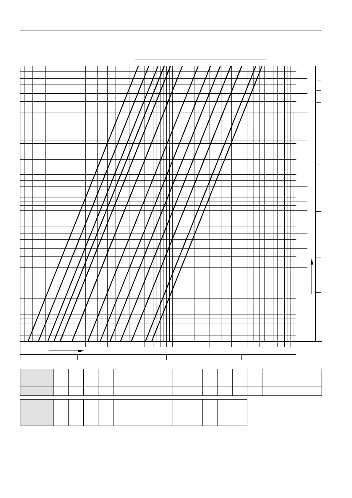
Flow Data Kombi-3-plus BLUE (V5010), DN25
0,3
0,6
0,8
re-setting
1,5 2
1,2
1
2,5 3
3,5
4
5,9
5
0
0
1
7
,
8
6
8
5
7
0
,
6
4
0
,
5
3
0
,
4
0
,
3
2
0
,
2
0
0
0
0
1
9
8
0
,
7
1
6
60 100kg/h
Flow
0,017 0,05
l/sec
Pre-setting
kv-value
cv-value
0,3 0,4 0,6 0,8 1,0 1,2 1,4 1,6 1,8 2,0 2,2 2,4 2,6 2,8 3,0 3,2 3,4 3,6
0,68 0,72 0,84 0,97 1,10 1,30 1,50 1,70 1,90 2,10 2,30 2,50 2,70 2,95 3,20 3,48 3,76 4,05
0,80 0,84 0,98 1,13 1,29 1,52 1,76 1,99 2,22 2,46 2,69 2,93 3,16 3,45 3,74 4,07 4,40 4,74
2 4 5 6 7 8 100093 2 4 5 6 7 8 1000093
0,1
0,25
0,5 1,0
2,5
5
4
5
,
0
3
3
,
0
2
r
a
b
m
0
1
.
I
p
.
o
S
r
a
.
d
P
P
e
r
u
s
5
0
s
4
0
e
1
r
,
0
0
1
P
Pre-setting
kv-value
cv-value
3,8 4,0 4,2 4,4 4,6 4,8 5,0 5,2 5,4 5,6 5,8 5,9 = open
4,34 4,64 4,94 5,24 5,52 5,80 6,06 6,30 6,50 6,65 6,75 kvs = 6,80
5,08 5,43 5,78 6,13 6,46 6,79 7,09 7,37 7,61 7,78 7,90 7,96
NOTE: Flow diagram is ONLY valid for valve WITHOUT installed actuator (-adapter) or Kombi-Diaphragm Unit
EN0H-0046GE25 R0402 14 Honeywell AG • All rights reserved
Page 15

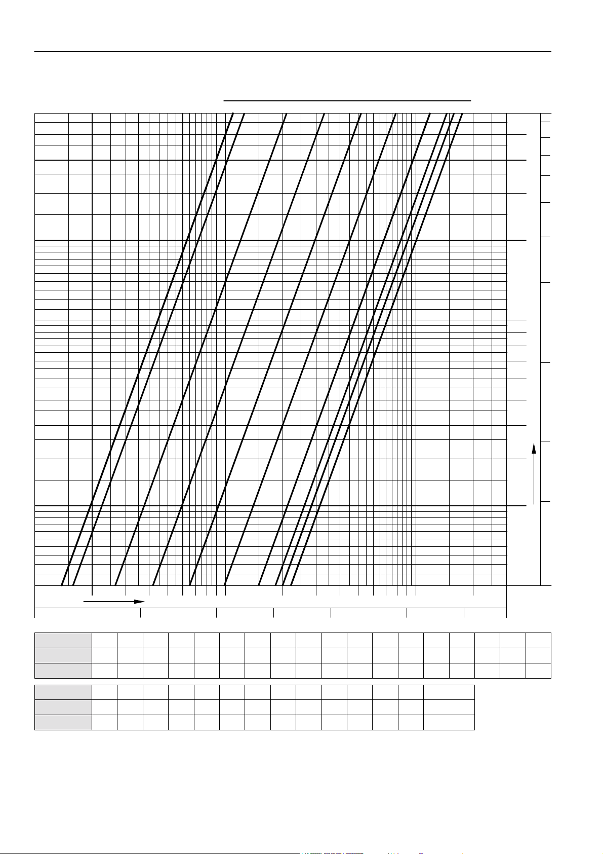
Flow Data Kombi-3-plus BLUE (V5010), DN32
P
1
0,5
1,2
re-setting
1,5 2
KOMBI-3-PLUS (V5000, V5010, V5100)
4
3
56
6,5
6
5
4
3
2
0
0
0
0
0
0
1
1
9
8
7
6
7
,
8
8
7
0
,
6
0
,
5
0
,
4
0
,
3
0
,
2
0
,
1
100
Flow
Pre-setting
kv-value
cv-value
5
4
3
2
r
p
a
o
b
r
a
d
P
m
e
r
u
s
0
s
0
e
r
0
0
P
1
1
4kg/h
2
3 5 6 7 8 10009 2 4 5 6 7 8 10000932
0,25
0,50,028 0,1 5,0l/sec
1,0
2,5
3
0,5 0,6 0,8 1,0 1,2 1,4 1,6 1,8 2,0 2,2 2,4 2,6 2,8 3,0 3,2 3,4 3,6 3,8
1,40 1,45 1,55 1,60 2,60 3,70 4,80 5,90 6,50 6,90 7,50 8,30 9,20 10,2 11,2 12,2 13,2 14,1
1,64 1,70 1,81 1,87 3,04 4,33 5,62 6,90 7,61 8,07 8,78 9,71 10,8 11,9 13,1 14,3 15,4 16,5
5
,
0
3
,
0
.
I
.
S
.
P
5
4
1
,
0
Pre-setting
kv-value
cv-value
4,0 4,2 4,4 4,6 4,8 5,0 5,2 5,4 5,6 5,8 6,0 6,2 6,4 6,5 = open
15,0 15,8 16,5 17,1 17,7 18,2 18,6 19,0 19,4 19,7 20,0 20,4 20,8 kvs = 21,0
17,6 18,5 19,3 20,0 20,7 21,3 21,8 22,2 22,7 23,0 23,4 23,9 24,3 24,6
NOTE: Flow diagram is ONLY valid for valve WITHOUT installed actuator (-adapter) or Kombi-Diaphragm Unit
Honeywell AG • All rights reserved 15 EN0H-0046GE25 R0402
Page 16
KOMBI-3-PLUS (V5000, V5010, V5100)
P
Flow Data Kombi-3-plus BLUE (V5010), DN40
1
0,5
1,2
re-setting
1,5 2
7
6
5
3
4
6,5
0
0
1
,
8
6
8
5
7
0
,
6
4
0
,
5
3
0
,
4
0
,
3
2
0
,
2
0
0
0
0
1
9
8
0
,
7
1
6
100
Flow
Pre-setting
kv-value
cv-value
5
4
3
2
r
p
a
o
b
r
a
d
P
m
e
r
u
s
0
s
0
e
r
0
0
P
1
1
4kg/h
2
3 5 6 7 8 10009 2 4 5 6 7 8 10000932
0,25
0,50,028 0,1 5,0l/sec
1,0
2,5
3
0,5 0,6 0,8 1,0 1,2 1,4 1,6 1,8 2,0 2,2 2,4 2,6 2,8 3,0 3,2 3,4 3,6 3,8
1,40 1,45 1,55 1,60 2,60 3,70 4,80 5,90 6,50 6,90 7,50 8,30 9,20 10,2 11,2 12,2 13,2 14,1
1,64 1,70 1,81 1,87 3,04 4,33 5,62 6,90 7,61 8,07 8,78 9,71 10,8 11,9 13,1 14,3 15,4 16,5
5
,
0
3
,
0
.
I
.
S
.
P
5
4
1
,
0
Pre-setting
kv-value
cv-value
4,0 4,2 4,4 4,6 4,8 5,0 5,2 5,4 5,6 5,8 6,0 6,2 6,4 6,5 = open
15,0 15,8 16,5 17,1 17,7 18,2 18,6 19,0 19,4 19,7 20,0 20,8 21,6 kvs = 22,0
17,6 18,5 19,3 20,0 20,7 21,3 21,8 22,2 22,7 23,0 23,4 24,3 25,3 25,7
NOTE: Flow diagram is ONLY valid for valve WITHOUT installed actuator (-adapter) or Kombi-Diaphragm Unit
EN0H-0046GE25 R0402 16 Honeywell AG • All rights reserved
Page 17

Flow Data Kombi-3-plus BLUE (V5010), DN50
P
1
1,5
re-setting
2
KOMBI-3-PLUS (V5000, V5010, V5100)
2,5 3
3,5
4
57
7,9
6
5
4
3
2
0
0
0
0
0
0
1
1
9
8
7
6
7
,
8
8
7
0
,
6
0
,
5
0
,
4
0
,
3
0
,
2
0
,
1
100
Flow
Pre-setting
kv-value
cv-value
5
4
3
2
r
p
a
o
b
r
a
d
P
m
e
r
u
s
0
s
0
e
r
0
0
1
1
P
4kg/h
2
3 5 6 7 8 10009 2 4 5 6 7 8 10000932
0,25
0,50,028 0,1 5,0l/sec
1,0
2,5
3
1,0 1,2 1,4 1,6 1,8 2,0 2,2 2,4 2,6 2,8 3,0 3,2 3,4 3,6 3,8 4,0 4,2 4,4
0,80 1,25 1,88 2,72 3,78 5,10 6,68 8,54 10,7 13,0 15,6 18,7 21,0 22,8 24,3 25,4 26,4 27,2
0,94 1,46 2,20 3,18 4,42 5,97 7,82 9,99 12,5 15,2 18,3 21,9 24,6 26,7 28,4 29,7 30,9 31,8
5
,
0
3
,
0
.
I
.
S
.
P
5
4
1
,
0
Pre-setting
kv-value
cv-value
4,6 4,8 5,0 5,2 5,4 5,6 5,8 6,0 6,2 6,4 6,6 6,8 7,0 7,2 7,4 7,6 7,9 = open
28,0 28,8 29,5 30,2 31,0 31,7 32,4 33,0 33,6 34,1 34,6 35,0 35,4 35,8 36,2 36,8 kvs = 38,0
32,8 33,7 34,5 35,3 36,3 37,1 37,9 38,6 39,3 39,9 40,5 41,0 41,4 41,9 42,4 43,1 44,5
Honeywell AG • All rights reserved 17 EN0H-0046GE25 R0402
Page 18

KOMBI-3-PLUS (V5000, V5010, V5100)
P
Flow Data Kombi-3-plus BLUE (V5010), DN65
1,5 2 3 41
re-setting
5
67,9
7
,
8
6
8
5
7
0
,
6
4
0
,
5
3
0
,
4
0
,
3
2
0
,
2
0
0
0
0
0
0
1
1
9
8
0
,
7
1
6
100
kg/h
Flow
Pre-setting
kv-value
cv-value
5
4
3
2
r
a
b
m
0
1
3 2 4 5 6 7 8 100009324563
2 4 5 6 7 8 1000
0,1
9
0,25 0,50,028
1,0
2,5
5,0l/sec
10,0
1,0 1,2 1,4 1,6 1,8 2,0 2,2 2,4 2,6 2,8 3,0 3,2 3,4 3,6 3,8 4,0 4,2 4,4
1,40 1,50 2,50 3,50 4,50 5,50 7,70 10,0 12,2 14,5 16,7 19,0 21,3 23,7 26,0 28,3 30,1 31,9
1,64 1,76 2,93 4,10 5,27 6,44 9,01 11,7 14,3 17,0 19,5 22,2 24,9 27,7 30,4 33,1 35,2 37,3
5
,
0
3
,
0
.
I
p
.
o
S
r
a
.
d
P
P
e
r
u
s
5
0
s
4
0
e
1
r
,
0
0
P
1
Pre-setting
kv-value
cv-value
4,6 4,8 5,0 5,2 5,4 5,6 5,8 6,0 6,2 6,4 6,6 6,8 7,0 7,2 7,4 7,6 7,9 = open
33,6 35,4 37,2 38,6 40,1 41,5 43,0 44,0 44,9 45,4 46,0 46,5 47,0 47,1 47,3 47,4 kvs = 47,7
39,3 41,4 43,5 45,2 46,9 48,6 50,3 51,5 52,5 53,1 53,8 54,4 55,0 55,0 55,3 55,5 55,8
EN0H-0046GE25 R0402 18 Honeywell AG • All rights reserved
Page 19

Flow Data Kombi-3-plus BLUE (V5010), DN80
P
KOMBI-3-PLUS (V5000, V5010, V5100)
re-setting
1,5 2 3 41
56 7,97
0
0
1
7
,
8
6
8
5
7
0
,
6
4
0
,
5
3
0
,
4
0
,
3
2
0
,
2
0
0
0
0
1
9
8
0
,
7
1
6
100
kg/h
Flow
Pre-setting
kv-value
kv-value
5
4
3
2
r
a
b
m
0
1
3 2 4 5 6 7 8 100009324563
2 4 5 6 7 8 1000
0,1
9
0,25 0,50,028
1,0
2,5
5,0l/sec
10,0
1,0 1,2 1,4 1,6 1,8 2,0 2,2 2,4 2,6 2,8 3,0 3,2 3,4 3,6 3,8 4,0 4,2 4,4
2,20 4,20 6,20 8,10 10,1 12,1 15,3 18,5 21,6 24,8 28,0 30,9 33,9 36,8 39,8 42,7 44,9 47,0
2,57 4,91 7,25 9,48 11,8 14,2 17,9 21,6 25,3 29,0 32,8 36,1 39,7 43,1 46,6 50,0 52,5 55,0
5
,
0
3
,
0
.
I
p
.
o
S
r
a
.
d
P
P
e
r
u
s
5
0
s
4
0
e
1
r
,
0
0
P
1
Pre-setting
kv-value
kv-value
4,6 4,8 5,0 5,2 5,4 5,6 5,8 6,0 6,2 6,4 6,6 6,8 7,0 7,2 7,4 7,6 7,9 = open
49,2 51,3 53,5 55,2 57,0 58,7 60,5 62,2 63,4 64,5 65,7 66,8 68,0 68,6 69,2 69,8 kvs = 71,0
57,6 60,0 62,6 64,6 66,7 68,7 70,8 72,8 74,2 75,5 76,9 78,2 79,6 80,3 81,0 81,7 83,1
Honeywell AG • All rights reserved 19 EN0H-0046GE25 R0402
Page 20

KOMBI-3-PLUS (V5000, V5010, V5100)
Influence of Coolants on Fl ow Va lue s
The flow through a valve is defined by the kv-value. The kv-value is the flow m through a valve in [m³/h] at a differential pressure
of 1 bar (14,5 P.S.I.) and is only valid for fluids with a density of σ0 = 1000 kg/m³. This condition is met by water at a temperature
of 20°C (68°F). For fluids with another density the following formula can be applied:
Kv
Medium
m
=
p
∆
ρ
Medium
×
ρ
0
Correction Factor f
When the density σ is expressed in t/m³ instead of kg/m³ the correction factor f is the result. The correction factor f can be used
to re-calculate kv-value, pressure drop and flow:
KvKv
Medium
Medium
Normal water 100% 1,000 0,998 0,994 0,988 0,981 0,972
Ethylen glycol 70% 1,052 1,047 1,041 1,033 1,024 1,015
e.g. Antifrogen N 50% 1,086 1,079 1,070 1,061 1,052 1,042
Propylen glycol 70% 1,035 1,029 1,021 1,012 1,002 0,991
e.g. Antifrogen L 50% 1,053 1,044 1,035 1,025 1,014 1,002
0
f
Table 1. Values for correction factor f
water part 5°C (41°F) 20°C (68°F) 35°C (95°F) 50°C (122°F) 65°C (149°F) 80°C (176°F)
Medium
fpp
×∆=∆
0
Correction factor f
Medium
mm
1
×=
1
×=
0
f
Control Products
Honeywell AG Phone: (49) 2932 9880
Zu den Ruhrwiesen 3 Fax: (49) 2932 988239
D-59755 Arnsberg-Neheim mng@honeywell.com http://europe.hbc.honeywell.com
EN0H-0046GE25 R0402 20 Subject to change • All rights reserved
 Loading...