

Honeywell V48F, V48A, V88A, V88J, V48J User Manual
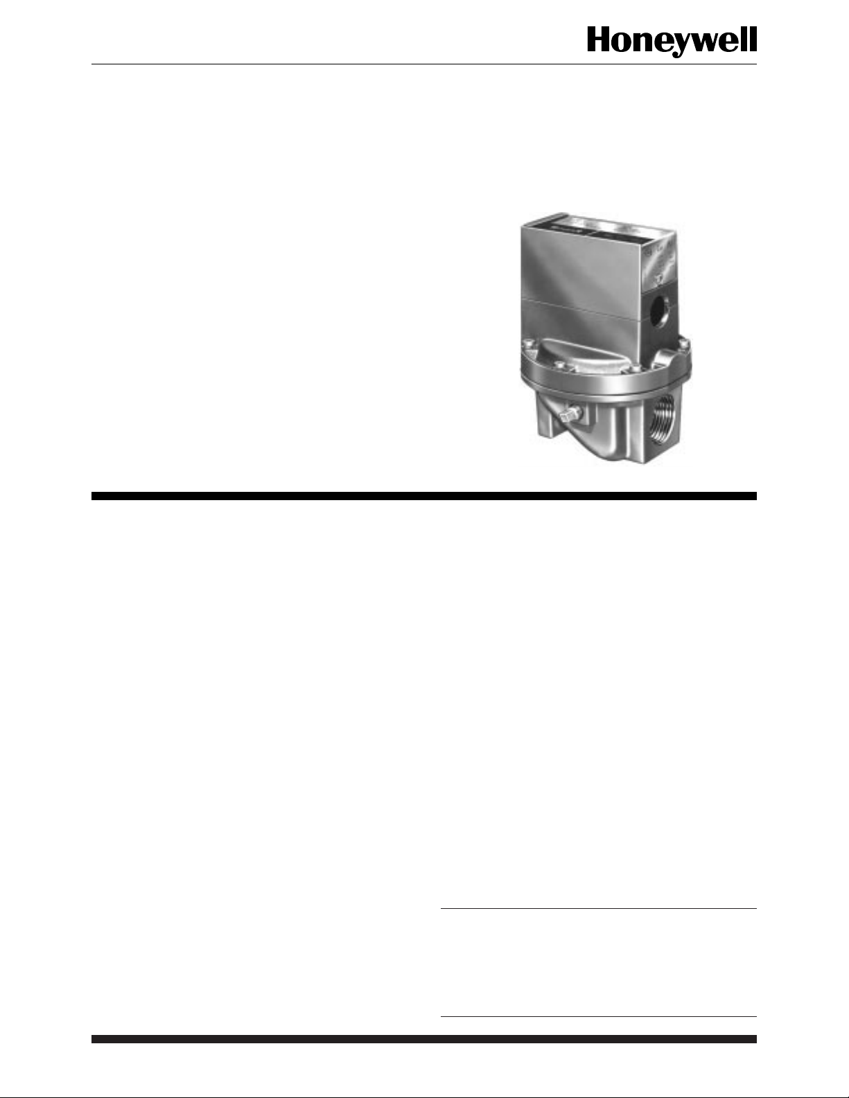
V48A,F,J; V88A,J
Diaphragm Gas Valves
The V48 and V88 are solenoid-operated diaphragm valves suitable for LP (Liquefied Petroleum), natural, and manufactured gases. They are
normally used on atmospheric boilers, commercial
water heaters, and rooftop heaters.
■ Line voltage, 2-wire thermostat or controller used
with a V48; V88 used with 24V thermostat.
■ Valves provide slow opening and fast closing.
■ Two second maximum closing time for 2 through
3 in. valves.
■ One second maximum closing time for 3/4 through
1-1/2 in. valves.
■ V48J, V88J rated for 150° F ambient temperature.
■ V48F rated for 5 psi (lb. per sq in.) [34.5 kPa].
V48A and V88A rated for either 1/2 or 1 psi [3.4 or
6.9 kPa], depending on model. V48J and V88J rated
for 1 psi [6.9 kPa].
■ One model for natural and LP gases.
■ Wide range of sizes and capacities.
■ Firm closing; diaphragm is both weight and spring
loaded.
■ Valve closes on power failure; recommended for
final shutoff service.
■ Adjustable or fixed bleed orifices available for in-
stallation by OEM.
■ Valve position indicator on 1-1/4 in. V48A2227 and
2 in. V48F1103 Valves.
CONTENTS
Specifications............................................... 2
Ordering Information ..................................2
Installation................................................... 5
Operation ..................................................... 8
Checkout and Troubleshooting ................... 9
Service Information ................................... 10
F.P. • Rev. 9-94 • ©Honeywell Inc. 1994 • Form Number 60-2080—8
1 60-2080—8

V48A,F,J; V88A,J
SPECIFICATIONS • ORDERING INFORMATION
Specifications
MODELS:
V48A (120 Vac) or V88A (24 Vac) solenoid operated
diaphragm valves for 1/2 or 1 psi [3.4 or 6.9 kPa]
maximum operating pressure.
V48F (120 Vac) solenoid operated diaphragm valve for
5 psi [34.5 kPa] maximum operating pressure.
V48J (120 Vac) or V88J (24 Vac) solenoid operated
diaphragm valves for 1 psi [6.9 kPa] operating pressure and 150° F maximum ambient temperature.
TYPE OF GAS: Suitable for liquefied petroleum (LP), natu-
ral, manufactured, and sulfur-bearing gases.
VALVE CAPACITY: See table in Fig. 2.
VALVE PATTERN: Straight-through, nonoffset.
VALVE BODY MATERIAL: Die-cast aluminum.
PILOT TAPPING (see Table 1 for thread type): 3/4 through
1-1/2 inch valves: 1/8-27 NPT or 1/8-28 BSP.PI.
2 through 3 inch valves: 1/4-18 NPT or 1/4-19 BSP.PI.
BLEED TAPPING (see Table 1 for thread type): 1/8-
27 NPT or 1/8-28 BSP.PI.
VALVE OPENING TIME: Five seconds maximum at 2 oz/
in.2 [0.86 kPa] pressure. Adjustable bleed valve assem-
bly or fixed bleed orifices available for longer opening
time (NPT threads only; see Accessories).
VALVE CLOSING TIME (on power failure; measured at
2 oz/in.2 [0.86 kPa] pressure): 2 seconds maximum for 2
through 3 inch valves; 1 second maximum for 3/4 through
1-1/2 inch valves.
MAXIMUM OPERATING PRESSURE: See Table 1.
POWER CONSUMPTION (maximum): 9 watts or 15 VA.
AMBIENT TEMPERATURE RATING:
V48A,F and V88A: 32° F to 125° F [0° C to 52° C].
V48J and V88J: 32° F to 150° F [0° C to 65° C].
MAXIMUM FLUID TEMPERATURE:
V48A,F; V88A: 125° F.
V48J; V88J: 150° F.
THERMOSTAT HEAT ANTICIPATOR SETTING: For
60 Hz V88, set at 0.6A.
DIMENSIONS: See Fig. 1.
WEIGHT:
Pipe Size (in.) lb. kg
3/4 2-1/2 1.13
1 3 1.36
1-1/4 3-1/2 1.59
1-1/2 4 1.81
2 9 4.08
2-1/2 8-1/2 3.86
3 9-1/2 4.31
APPROVALS: (60 Hz models only):
Underwriters Laboratories Inc. Listed: File No. MH1639;
Guide No. YIOZ.
American Gas Association Design Certified: Report
No. 21-7B.
Canadian Gas Association Certified: For use with natu-
ral, manufactured, and mixed gases (60 Hz models
only).
NOTE: All models rated at 50 Hz and all models with
BSP.PI threads are not AGA Design Certified.
OPTIONAL FEATURE: Valve position indicator is avail-
able on 1-1/4 in. V48A2227 and 2 in. V48F1103.
REPLACEMENT COIL ASSEMBLIESa:
116930: 24V, 60 Hz V88A
116931: 120V, 60 Hz V48A.
116932: 220V, 50 Hz V48A
116932: 240V, 60 Hz V48A
118888: 24V, 60 Hz V88J
139937: 120V, 60 Hz V48J
a
These V48/V88 bonnet assemblies and solenoid operators
are not compatible with old style valve bodies.
Ordering Information
When purchasing replacement and modernization products from your TRADELINE® wholesaler or your distributor, refer to the
TRADELINE
1. Order number. 5. Optional valve position indicator (1-1/4 inch and larger valves only),
2. Pipe size. if desired.
3. Operating pressure rating. 6. Replacement coil assembly, if desired.
4. Transformer for V88. 7. Accessories, if desired.
If you have additional questions, need further information, or would like to comment on our products or services, please write or phone:
1. Your local Honeywell Home and Building Control Sales Office (check white pages of phone directory).
2. Home and Building Control Customer Logistics
60-2080—8 2
®
catalog or price sheets for complete ordering number, or specify—
Honeywell Inc., 1885 Douglas Drive North
Minneapolis, Minnesota 55422-4386 (612) 951-1000.
In Canada—Honeywell Limited/Honeywell Limitée, 740 Ellesmere Road, Scarborough, Ontario M1P 2V9. International Sales
Offices in all principal cities of the world. Manufacturing in Australia, Canada, Finland, France, Germany, Japan, Mexico,
Netherlands, Spain, Taiwan, United Kingdom, U.S.A.

V48A,F,J; V88A,J
SPECIFICATIONS
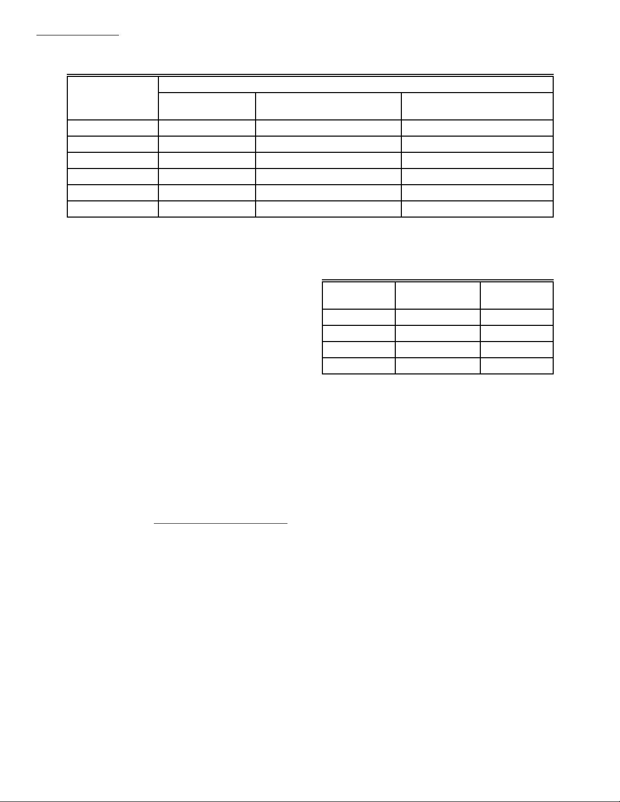
TABLE 1—MODELS AVAILABLE.
Model Voltage and Frequency (Psi) (Kpa) Pipe Size (in.)
Maximum Operating Pressure
Thread
Type
V48A 100V, 50 Hz 1/2 3.4 1, 1-1/4, 1-1/2 BSP.PI
1 6.9 2
120V, 60 Hz 1/2 3.4 3/4, 1, 1-1/4, 1-1/2 NPT
1 6.9 1, 1-1/4, 1-1/2, 2, 2-1/2, 3
220V, 50 Hz 1 6.9 1, 1-1/4, 1-1/2, 2, 3 BSP.PI
240V, 50 Hz 1 6.9 2 NPT
V48F 120V, 60 Hz 5 34.5 2 NPT
V48J 120V, 60 Hz
1 6.9 3/4, 1, 1-1/4, 1-1/2, 2 NPT
110V, 50 Hz
V88A 24V,60 Hz 1/2 3.4 3/4, 1, 1-1/4, 1-1/2 NPT
1 6.9 3/4, 1, 1-1/4, 1-1/2, 2, 2-1/2, 3
V88J 24V, 60 Hz 1 6.9 1, 1-1/4 NPT
a
A valve position indicator is on 1-1/4 in. V48A2227 and 2 in. V48F1103 Valves. BSP.PI—British Standard Parallel Internal
Threads; NPT—American Standard Taper Pipe Threads.
a
Fig. 1—Mounting dimensions of V48A,F,J and V88A,J Diaphragm Gas Valves.
APPROXIMATE DIMENSIONS
4-5/8
117.5
127.0
149.2
149.2
241.3
241.3
241.3
3-1/2
3-11/16
5-5/16
5-5/16
8-3/8
8-3/8
8-3/8
A
5
5-7/8
5-7/8
9-1/2
9-1/2
9-1/2
88.9
93.7
134.9
134.9
212.7
212.7
212.7
1-5/8
2-1/16
2-3/8
2-3/8
3-9/16
3-9/16
3-9/16
41.3
3-13/16
52.4
4-5/16
60.3
5-5/16
60.3
5-5/16
90.5
5-5/16
90.5
9-5/16
90.5
9-5/16
11
3
[93.7]
16
2
E
VALVE
SIZE
(IN.)
3/4
1-1/4
1-1/2
2-1/2
1
2
3
ABCDEF
IN. MM IN. MM IN. MM IN. MM IN. MM IN. MM
4-11/16
119.1
3/4
C
1-1/4
1-1/4
2-1/4
2-1/4
2-1/4
[46]
19.1
1
25.4
31.8
31.8
57.2
57.2
57.2
5-1/16
5-9/16
5-9/16
6-15/16
6-15/16
6-15/16
128.6
141.3
141.3
176.2
176.2
176.2
13
1
16
1
96.8
109.5
134.9
134.9
236.5
236.5
236.5
B
D
1
BLEED TAPPING: 1/8-27 NPT, OR 1/8-28 BSP. PL.
2
PILOT TAPING (2): 1/8-27 NPT FOR 3/4 THROUGH 1-1/2 IN. SIZES, 1/4-18 NPT FOR 2 THROUGH 3 IN. SIZES;
OR 1/8-28 BSP. PL FOR 1 THROUGH 1-1/2 IN. SIZES, 1/4-19 BSP.PL FOR 2 THROUGH 3 IN SIZES.
F
3 60-2080—8
M8487
V48A,F,J; V88A,J
SPECIFICATIONS
Valve Size (in.) No. Orifice
11 2 3
1-1/4 1 5 6
1-1/2 1 5 6
2 4 15 32
2-1/2 4 23 37
3 5 24 37
a
Time to reach 80% gas flow at fully open position. Inlet pressure; 4.2 in. wc [1.05 kPa] for 1 to 2 in. valves; 5 in. wc [1.25 kPa]
for 2-1/2 and 3 in. valves. Pressure drop across valves at fully open position. 0.2 in. wc [0.05 kPa] for 1 to 2 in. valves; 1 in. wc
[0.25 kPa] for 2-1/2 and 3 in. valves.
TABLE 2—EXTENDING VALVE OPENING TIME
Valve Opening Time (sec)
Orifice no. 122160,
0.018 in. [0.46 mm]
a
BY ADDING A BLEED ORIFICE.
Orifice no. 124674,
0.011 in. [0.28 mm]
ACCESSORIES:
Transformer AT72D: (40 VA) for all V88 models.
126590 Adjustable Bleed Valve Assembly: Consists of
adjustable bleed valve with sleeve and compression
nut for connecting to 1/4 in. tubing; see Fig. 8.
(Not available for valves with BSP.PI. threads.)
Bleed Orifice: Fixed (see Table 2 for appropriate size):
124674 Orifice: 0.011 in. [0.28 mm] diameter.
122160 Orifice: 0.018 in. [0.46 mm] diameter.
126070 Orifice Tool: Required for field mounting a
bleed orifice (in valves with NPT threads only).
GAS VALVE SIZING
1. Check the burner nameplate for (a) the type of gas
used, and (b) the gas flow capacity. The capacity will be
listed in Btu/h (Btu per hour) or in cf/h (cubic feet per
hour).
2. Call the gas utility for information on (a) the specific
gravity (sp gr) and (b) Btu per cubic feet (Btu/cu ft) for type
of gas used.
3. Find the capacity in cf/h. If the capacity is listed in
Btu/h, convert to cf/h by the following formula.
Capacity in cf/h = Btu/h (from burner nameplate)
Btu/cu ft (from gas utility)
4. For gases with specific gravities other than 0.64,
multiply the burner cf/h by the conversion factor in Table 3.
5. Use the corrected capacity in cf/h when determining
the gas valve size in Fig. 2.
6. Determine the maximum pressure drop across the
valve, and draw a horizontal line at this pressure in Fig. 2.
TABLE 3—CONVERSION FACTORS.
Type of
Gas
Average Specific
Gravity
Multiply
cf/h by
Manufactured 0.60 1.033
Mixed 0.70 0.956
LP—Propane 1.53 0.647
LP—Butane 1.98 0.569
7. Draw a vertical line in Fig. 2 at the capacity (cf/h)
previously determined. Use the corrected capacity for a
gas with a specific gravity other than 0.64.
8. Use the valve size at the intersection of the horizontal
and vertical lines. If the intersection is between valve sizes,
use the next higher valve size to the right.
TO SIZE TWO IDENTICAL VALVES PIPED
IN SERIES
1. Find the cf/h for the type of gas used.
2. Consider both valves as one unit. Determine the total
maximum pressure drop across the unit.
3. Find the pressure drop across the first valve by assuming it to be 45 percent of the total pressure drop.
4. Find the valve size from Fig. 2.
5. The second valve will be the same size as the first
valve.
60-2080—8 4
 Loading...