

Page 1
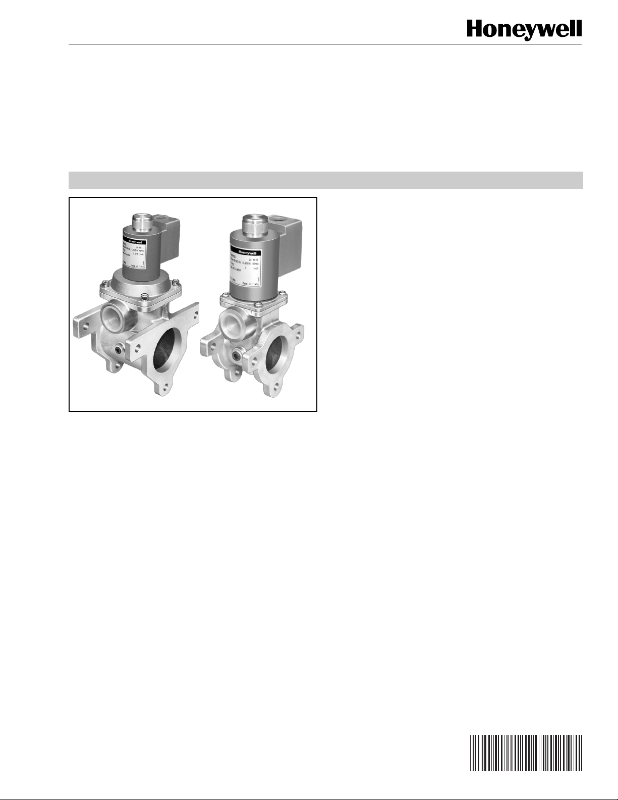
Normally Open Vent Valve
APPLICATION
The V4297S provides the vent function in a double block and
bleed configuration. The valve is part of the Honeywell
Integrated Valve Train System, which allows gas train
components to be directly bolted together.
V4297S
PRODUCT DATA
FEATURES
• Used with natural, manufactured, mixed or liquefied
petroleum (LP) gases.
• V4297S valves are normally open valves to be used as
vent valves in double block and bleed
configurations. The gas flows through the vent
connection when the valve is not energized.
• V4297S are used with 110/120Vac 50/60Hz
controllers.
•Two valve body types (small and large)
applicable to seven pipe sizes:
Small body type for 3/4 in. (19 mm), 1 in. (25 mm),
1-1/4 in. (32 mm), 1-1/2 in. (38 mm) and
2 in. (51 mm) pipes.
Large body type for 2 in. (51 mm),
2-1/2 in. (64 mm) and 3 in. (76 mm) pipes.
• Small body has a 1 in. NPT threaded vent connection.
Large body has a 1-1/4 in. NPT threaded vent
connection.
•Two 1/4 in. NPT threaded pressure taps available for
the small body valve, three for the large body valve.
• NEMA 1 enclosure standard.
• V4297S is not gas flow direction dependent. It can be
connected either way in the valve train.
• Unpainted die-cast aluminum body.
® U.S. Registered Trademark
Copyright © 1999 Honeywell Inc. • All Rights Reserved
65-0244
Page 2
V4297S NORMALLY OPEN VENT VALVE
SPECIFICATIONS
IMPORTANT
The specifications in this publication do not include
normal manufacturing tolerances; therefore, an
individual unit may not exactly match the
specifications listed. Also, this product is tested and
calibrated under closely controlled conditions, and
some minor differences in performance can be
expected if those conditions are changed.
Models:
V4297S Normally Open Vent Valve.
Type of Gas:
Natural, manufactured, mixed or liquefied petroleum (LP) only.
Gas Train Pipe Size:
3/4 in. (19 mm), 1 in. (25 mm), 1-1/4 in. (32 mm),
1-1/2 in. (38 mm), 2 in. (51 mm), 2-1/2 in. (64 mm),
3 in. (76 mm).
Pipe Threads:
Small Body: 1 in. NPT threaded vent connection.
Large Body: 1-1/4 in. NPT threaded vent connection.
Operating Pressure Rating:
Maximum: 5 psi.
Material:
Die-cast aluminum.
Mounting:
Bolted to Integrated Valve Train components.
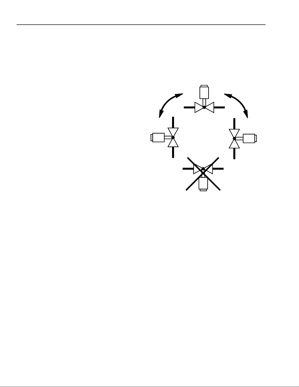
Mounting Position:
Vertical to 90 degrees from vertical. See Fig. 1.
Valve Capacity through Vent Connection:
Ratings: 1 in. (0.25 kPa) pressure drop for gas with 0.64 sp gr.
Small Body: 714 cfh.
Large Body: 1115 cfh.
Bolt/Nut Fasteners:
Bolts, nuts and O-rings are provided with the safety shutoff
valves.
Tapping and plug:
Taps:1/4 in. NPT taps.
Plugs: Allen head.
Ambient Operating Temperature Rating:
-40°F to +145°F (-40°C to +63°C).
Fig. 1. Mounting positions for V4297S
Normally Open Vent Valve.
Electrical Terminations:
Screw terminal connections.
Current Draw:
V4297S small body, 120V: 0.2A.
V4297S large body, 120V: 0.34A.
Valve opening time: < 1 sec.
Valve closing time: < 1 sec.
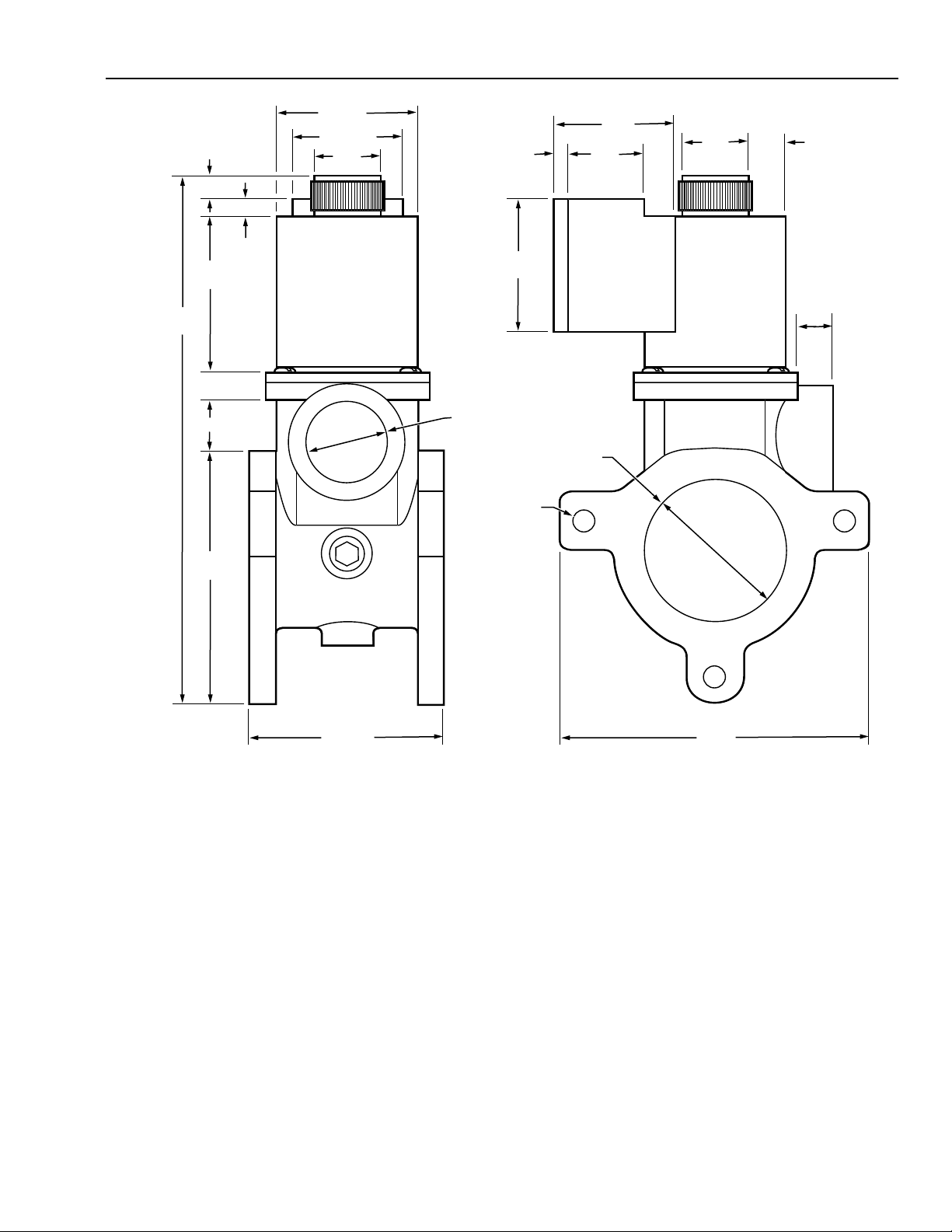
Dimensions:
See Fig. 2 and 3.
M16462
ORDERING INFORMATION
When purchasing replacement and modernization products from your TRADELINE® wholesaler or distributor, refer to the
TRADELINE® Catalog or price sheets for complete ordering number.
If you have additional questions, need further information, or would like to comment on our products or services, please write or
phone:
1. Your local Home and Building Control Sales Office (check white pages of your phone directory).
2. Home and Building Control Customer Logistics
Honeywell Inc., 1985 Douglas Drive North
Minneapolis, Minnesota 55422-4386
In Canada—Honeywell Limited/Honeywell Limitée, 35 Dynamic Drive, Scarborough, Ontario M1V 4Z9.
International Sales and Service Offices in all principal cities of the world. Manufacturing in Australia, Canada, Finland, France,
Germany, Japan, Mexico, Netherlands, Spain, Taiwan, United Kingdom, U.S.A.
65-0244
2
Page 3
V4297S NORMALLY OPEN VENT VALVE
3/8 (10)
(3 HOLES)
2-5/8
(69)
9-1/2
(241)
3-1/8
(79)
3/8 (10)
1/2 (13)
1/2 (13)
7/8 (22)
4-1/8
(105)
3-1/8 (79) 5 (127)
3/8
(10)
1/2
(13)
1-1/4
(32)
2 (51)
1-1/2
(32)
3/16 (5)
1-1/4
(32)
1-15/16 (49)
2-3/8 (60)
M16464
2 (51)
1 IN. NPT
Fig. 2. Approximate dimensions of smaller V4297 NOVV in in. (mm).
3
65-0244
Page 4

V4297S NORMALLY OPEN VENT VALVE
1/2 (13)
5/16 (8)
3
(76)
1-1/4 IN.
NPT
3/4
(18)
(51)
1/2 (13)
(3 HOLES)
2 (51)
3/16 (5)
2-5/8
(69)
3/4
(18)
1 (25)
2
1-1/2
(32)
5/8
(16)
3-1/8
(79)
1-1/2
(38)
12-3/8
(314)
1/2 (13)
5 (127) 8 (203)
Fig. 3. Approximate dimensions of larger V4297 NOVV in in. (mm).
Weight:
V4297S small body: 5.5 lb (2.5 kg).
V4297S large body: 9.5 lb (4.4 kg).
Replacement Parts:
BBA51316 Coil for small V4297S, complete with wiring box.
BBA51317 Coil for large V4297S, complete with wiring box.
Approvals:
Underwriters Laboratories Inc.: Listed.
Industrial Risk Insurers (formerly FIA): Acceptable.
International Approval Services (IAS): Design Certified.
4-1/2 (114)
M16465
65-0244
4
Page 5

V4297S NORMALLY OPEN VENT VALVE
INSTALLATION
When Installing this product…
1. Read these instructions carefully. Be sure to follow
Warning information carefully.
2. Check the ratings given in the instructions and on the
product to make sure the product is suitable for your
application.
3. Installer must be a trained, experienced flame
safeguard control technician.
4. After installation is complete, check out product
operation as provided in these instructions.
WARNING
Explosion Hazard And Electrical Shock Hazard.
Can cause explosion, serious injury or death.
Tu rn off gas supply before starting installation.
Disconnect power supply before beginning installation.
More than one disconnection can be involved.
Mounting
Refer to the Integrated Valve Train Installation Instructions,
form 66-1099, for instructions on mounting a V4297S
between two Safety Shutoff valves.
WIRING
2. Check the power supply circuit to verify the voltage and
frequency are the same as for the valve.
3. See Fig. 5 for typical V4297S field wiring with the
RM7800 Relay Module. Follow the burner manufacturer
wiring diagram, when provided. Refer to the relay
module wiring diagram for specific wiring terminal
designations.
4. Make wiring connections at the electrical terminations
provided in the valve wiring compartment.
V4297S
M16463
GROUND
NEUTRAL
LINE
VOLTAGE
N
L
MAIN VALVE
G
L2
4
9
120 Vac
RM7800
(TYPICAL)
1. Make sure that all wiring agrees with all applicable local
codes, ordinances and regulations. An opening is
provided to accommodate rigid conduit or armored
cable for line voltage operation (see Fig. 4).
Fig. 4. Wiring compartment of V4297 NOVV.
Fig. 5. Typical wiring diagram for V4297 NOVV.
OPERATION AND CHECKOUT
Operation
The V4297S is a normally open valve. The valve closes when
it is energized, and opens when the power is removed. It
provides the vent function in a double block and bleed
application. The V4297S is open when the two Safety Shutoff
Valves (SSOV) are closed, and is closed when the two SSOV
are open.
Checkout
WARNING
Explosion Hazard And Electrical Shock Hazard.
Can cause explosion, serious injury or death.
1. Do not put the system into service until you have
satisfactorily completed the following Valve Leak
Test, all applicable tests described in the Checkout
section of the instructions for the flame safeguard
control, and any other tests required by the burner
manufacturer.
2. All tests must be performed by a trained,
experienced, flame safeguard control technician.
3. Close all manual fuel shutoff valves as soon as
trouble occurs.
After the installation is completed, cycle the valve several
times with the manual fuel shutoff cock closed. Make sure the
valve functions properly. Also perform the Valve Leak Test
before putting the valve into service.
5
65-0244
Page 6

V4297S NORMALLY OPEN VENT VALVE
Valve Leak Test
This is a test for checking the closure tightness of the gas
valve. It should be performed only by trained, experienced,
flame safeguard control technicians during the initial startup
of the burner system, or whenever the valve is replaced.
1. Energize the V4297S to close the vent connection.
2. Close the manual gas cock downstream of the second
Safety Shutoff Valve (SSOV).
3. Tu rn on main gas and make sure the gas reaches the
V4297S (energize the first SSOV).
4. Check the V4297S for gas leaks using a gas leak
detector or a soap solution.
TROUBLESHOOTING
WARNING
Electrical Shock Hazard.
Can cause serious injury or death.
Use extreme caution while troubleshooting; line
voltage is present.
IMPORTANT
Do not replace the valve until all other sources of
trouble are eliminated.
Troubleshooting Procedure
If the valve does not close when the thermostat or controller
is calling for heat:
1. Check for line voltage at the valve lead wires or terminal
block.
2. If there is no voltage at the valve lead wires or terminal
block, make sure:
a. line voltage power is connected to the master
switch;
b. master switch is closed and overload protection
(circuit breaker, fuse or similar device) has not
opened the power line.
3. If there is still no voltage at the valve lead wires or
terminal block, make sure all appropriate contacts in the
thermostat or controller, limits and flame safeguard
controls are closed. If one or more are open, determine
the cause(s); correct the trouble, and proceed.
4. If there is proper voltage at the valve but the valve still
does not close, check for normal gas pressure.
5. If the valve still does not close, replace the valve.
SERVICE INFORMATION
WARNING
Explosion and Electrical Shock Hazard.
Can cause explosion, serious injury or death.
1. Turn off the gas supply and disconnect all electrical
power to the valve before servicing.
IMPORTANT
Only trained, experienced flame safeguard control
technicians should attempt to service or repair flame
safeguard controls and burner assemblies.
Scheduled Inspection and Maintenance
Set up and follow a schedule for periodic inspection and
maintenance, including the burner, all other controls, and the
valve(s). It is recommended that the valve leak test in the
Checkout section be included in this schedule. Refer to the
instructions for the primary safety control(s) for more
inspection and maintenance information.
If the valve does not open when one or more of the
appropriate contacts in the thermostat, controller, limits or
flame safeguard control is open:
1. Make sure the valve is wired in the correct circuit.
2. Open the master switch to remove power from the
valve.
3. If the valve opens now, check the wiring for the valve
and correct the wiring as necessary.
4. Check for a short in the electrical circuit and repair it as
necessary.
65-0244
6
Page 7

V4297S NORMALLY OPEN VENT VALVE
7
65-0244
Page 8

V4297S NORMALLY OPEN VENT VALVE
Home and Building Control
Honeywell Inc.
Honeywell Plaza
P.O. Box 524
Minneapolis MN 55408-0524
Honeywell Latin American Region
480 Sawgrass Corporate Parkway
Suite 200
Sunrise FL 33325
65-0244 G.R. 6-99
65-0244
Home and Building Control
Honeywell Limited-Honeywell Limitée
155 Gordon Baker Road
North York, Ontario
M2H 3N7
Honeywell Europe S.A.
3 Avenue du Bourget
1140 Brussels
Belgium
Printed in U.S.A. on recycled
paper containing at least 10%
post-consumer paper fibers.
8
Honeywell Asia Pacific Inc.
Room 3213-3225
Sun Hung Kai Centre
No. 30 Harbour Road
Wanchai
Hong Kong
www.honeywell.com/building/components
 Loading...