

Page 1
Solenoid Safety Shut-Off Valve
APPLICATION
The V4297A controls gas flow to commercial and industrial
burners. The valve is part of the Honeywell Integrated Valve
Train System that allows gas train components to be directly
bolted together.
V4297A
PRODUCT DATA
FEATURES
• Used with natural or liquefied petroleum (LP) gases.
• V4297A normally closed valves are rated for final
shutoff service (safety shutoff).
• One valve body (small) applicable to five pipe sizes:
• 3/4 in. (19 mm), 1 in. (25 mm), 1-1/4 in. (32 mm),
1-1/2 in. (38 mm) and 2 in. (51 mm) pipes.
• Two valves with different capacities:
• V4297A1005: 1 in. (25 mm) internal opening
(small capacity).
• V4297A1013: 2 in. (51 mm) internal opening
(high capacity).
• Two 1/4 in. NPT upstream and one 1/4 in. NPT
downstream pressure taps and plugs.
• Accepts C6097 Pressure Switch mounted directly
to flange (upstream pressure tap only).
• NEMA 1 enclosure standard.
• Optional Visual Position Indicator available.
• Unpainted aluminum body.
® U.S. Registered Trademark
Copyright © 2001 Honeywell • All Rights Reserved
Contents
Application ........................................................................ 1
Features ........................................................................... 1
Specifications ................................................................... 2
Ordering Information ........................................................ 2
Installation ........................................................................ 6
Wiring ............................................................................... 6
Operation And Checkout .................................................. 7
Troubleshooting ................................................................ 8
Service Information ............................................ ...... ...... .. 8
65-0246-1
Page 2
SOLENOID SAFETY SHUT-OFF VALVE
SPECIFICATIONS
IMPORTANT
The specifications in this publication do not include
normal manufacturing tolerances; therefore, an
individual unit may not exactly match the
specifications listed. Also, this product is tested and
calibrated under closely controlled conditions, and
some minor differences in performance can be
expected if those conditions are changed.
Models:
V4297A1005: small body, 1 in. (25 mm) internal opening
(small capacity).
V4297A1013: small body, 2 in. (51 mm) internal opening
(high capacity).
T yp es of Gas:
Gas Train Pipe Size:
1-1/4 in. (32 mm), 1-1/ 2 in. (38 mm), 2 in. (51 mm).
Operating Pressure Rating:
Valve Capacities:
Valve Type
Small Flange
Safety Shut-Off
(large flow)
V4297A1013
Safety Shut-Off
(small flow)
V4297A1005
a
Ratings at 1 in. (.025 kPa) pressure drop for gas with
0.64 sp gr.
Flow Curves:
Natural, manufactured, mixed or LP only.
3/4 in. (19 mm), 1 in. (25 mm),
Maximum: 5 psi.
See Table 1.
Table 1. Valve Flow Capacities.
Pipe Diameter
(in.)
Flow Capacity
(cfh)
3/4 1190
1 1460
1-1/4 2260
1-1/2 2735
23060
3/4 650
1700
1-1/4 780
See Table 1 and Fig. 1 through 8.
a
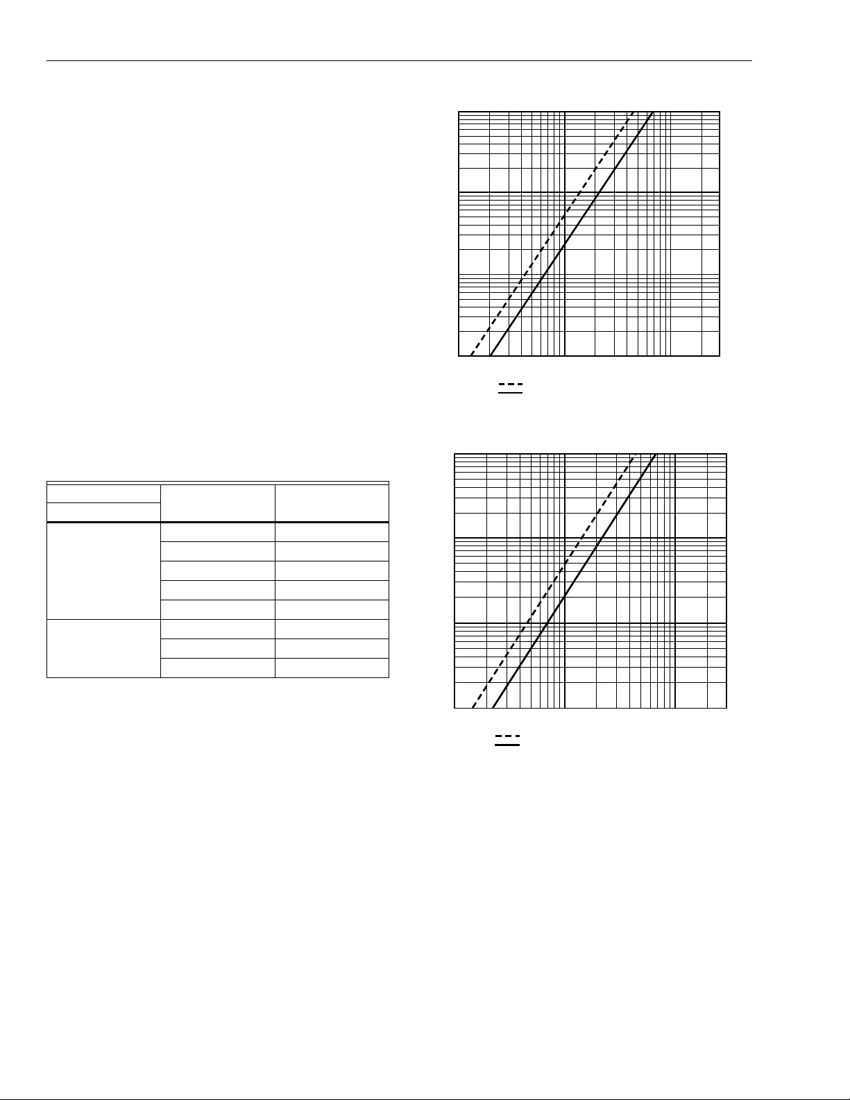
100
10
1
PRESSURE DROP (IN. WC)
0.1
100 1,000 10,000 30,000
LEGEND:
FLOW CAPACITY (cfh)
Propane, sp. gr = 1.53.
Natural Gas, sp. gr = 0.64.
M16531
Fig. 1. Flow curves for V4297A1005 SSOV
with 3/4 in. (19 mm) pipe adapter.
100
10
1
PRESSURE DROP (IN. WC)
0.1
100 1,000 10,000 30,000
LEGEND:
FLOW CAPACITY (cfh)
Propane, sp. gr = 1.53.
Natural Gas, sp. gr = 0.64.
M16533
Fig. 2. Flow curves for V4297A1005 SSOV
with 1 in. (25 mm) pipe adapter.
ORDERING INFORMATION
When purchasing replacement and modernization products from your TRADELINE® wholesaler or distributor, refer to the
TRADELINE® Catalog or price sheets for complete ordering number.
If you have additional questions, need further information, or would like to comment on our products or services, please write or
phone:
1.
Your local Home and Building Control Sales Office (check white pages of your phone directory).
2.
Home and Building Control Customer Relations
Honeywell, 1885 Douglas Drive North
Minneapolis, Minnesota 55422-4386 (800) 328-5111
In Canada—Honeywell Limited/Honeywell Limitée, 35 Dynamic Drive, Scarborough, Ontario M1V 4Z9.
International Sales and Service Offices in all principal cities of the world. Manufacturing in Australia, Canada, Finland, France,
Germany, Japan, Mexico, Netherlands, Spain, Taiwan, United Kingdom, U.S.A.
65-0246—1 2
Page 3

100
100
100 1,000 10,000 30,000
10
1
0.1
PRESSURE DROP (IN. WC)
FLOW CAPACITY (cfh)
M16536
Propane, sp. gr = 1.53.
Natural Gas, sp. gr = 0.64.
LEGEND:
100
100 1,000 10,000 30,000
10
1
0.1
PRESSURE DROP (IN. WC)
FLOW CAPACITY (cfh)
M16537
Propane, sp. gr = 1.53.
Natural Gas, sp. gr = 0.64.
LEGEND:
10
1
PRESSURE DROP (IN. WC)
0.1
100 1,000 10,000 30,000
LEGEND:
FLOW CAPACITY (cfh)
Propane, sp. gr = 1.53.
Natural Gas, sp. gr = 0.64.
M16534
SOLENOID SAFETY SHUT-OFF VALVE
Fig. 3. Flow curves for V4297A1005 SSOV
with 1-1/4 in. (32 mm) pipe adapter
100
10
1
PRESSURE DROP (IN. WC)
0.1
100 1,000 10,000 30,000
LEGEND:
FLOW CAPACITY (cfh)
Propane, sp. gr = 1.53.
Natural Gas, sp. gr = 0.64.
M16535
Fig. 4. Flow curves for V4297A1013 SSOV
with 3/4 in. (19mm) pipe adapter.
Fig. 5. Flow curves for V4297A1013 SSOV
with 1 in. (25 mm) pipe adapter.
Fig. 6. Flow curves for V4297A1013 SSOV
with 1-1/4 in. (32 mm) pipe adapter.
3 65-0246—1
Page 4

SOLENOID SAFETY SHUT-OFF VALVE
100
10
1
PRESSURE DROP (IN. WC)
0.1
100 1,000 10,000 30,000
LEGEND:
FLOW CAPACITY (cfh)
Propane, sp. gr = 1.53.
Natural Gas, sp. gr = 0.64.
M16538
Fig. 7. Flow curves for V4297A1013 SSOV
with 1-1/2 in. (38 mm) pipe adapter.
100
Valve Body Material:
Mounting:
Directly bolted to Integrated Valve Train
components.
Mounting Position:
See Fig. 9.
Aluminum.
Vertical to 90 degrees from vertical.
M16462
10
1
PRESSURE DROP (IN. WC)
0.1
100 1,000 10,000 30,000
LEGEND:
FLOW CAPACITY (cfh)
Propane, sp. gr = 1.53.
Natural Gas, sp. gr = 0.64.
Fig. 8. Flow curves for V4297A1013 SSOV
with 2 in. (51 mm) pipe adapter.
Bolt/Nut Fasteners:
Small Body:
3/8-16 by 1-3/8, Grade 5 bolt. Metric equivalent:
M8 by 1.25 by 35 mm, Class 9.8.
Tapping and Plug:
Taps: 1/4 in. NPT taps.Plugs: 1/4 inch hex head.
Ambient Operating Temperature Range:
-40°F (-40°C) to +130°F (54°C).
M16539
Fig. 9. Mounting positions for V4297A
Solenoid Shut-off Safety Valve.
Electrical Terminations:
Screw terminal connections.
Current Draw:
V4297A1005 small capacity, 120V: 0.2A.
V4297A1013 high capacity, 120V: 0.5A.
Valve Opening Time:
Valve Closing Time:
Dimensions:
See Fig. 10 and 11.
< 1 sec.
< 1 sec.
Weight:
V4297A1005: 8 lb (3.6 kg)
V4297A1013: 14 lb (6.3 kg)
Replacement Parts:
BBA51315 Coil for V4297A1005.
BBA51318 Coil for V4297A1013.
Accessories:
Pipe Adapters:
32000109-001 3/4 in. NPT.
32000109-002 1 in. NPT.
32000109-003 1-1/4 in. NPT.
32000109-004 1-1/2 in. NPT.
32000109-005 2 in. NPT.
KTCPI001 Visual Position Indicator.
4074EYF Bag Assembly (bolts, nuts and washers), supplied.
4074EYK Bag Assembly (O-rings and tube of lubricant),
supplied.
65-0246—14
Page 5

SOLENOID SAFETY SHUT-OFF VALVE
M16541
2 (51)
9
(229)
2-3/4
(70)
TOP VIEW
5-5/8
(143)
1/2 (13)
5-3/4 (147)
Fig. 10. Approximate dimensions of V4297A1005 SSOV in in. (mm).
TOP VIEW
2-3/4
1-1/2 (38)
(70)
5 (127)
1-1/2 (38)
2-1/2 (64)
2 (51)
5-1/2 (140)
5-5/8 (143)
3-3/4 (95)
6-1/4
(159)
M16532
5-3/4 (147)
Fig. 11. Approximate dimensions of V4297A1013 SSOV in in. (mm).
Approvals:
Underwriters Laboratories Inc. (UL): Listed.
Industrial Risk Insurers (IRI), formerly FIA: Acceptable.
International Approval Services (IAS): Design Certified.
Factory Mutual (FM): Approved. (KTCPI001 Visual Position
Indicator required if used with pipe size larger than 3/4 in.)
10-1/4
(260)
2 (51)
1/2 (13)
5 (127)
5-1/2 (140)
5-5/8 (143)
NOTE: NOTE: Some application codes, such as NFPA,
require visual indication of the valve position as
provided by the KTCPI001 Visual Position Indicator.
5 65-0246—1
Page 6

SOLENOID SAFETY SHUT-OFF VALVE
INSTALLATION
When Installing This Product...
1.
Read these instructions carefully. Be sure to follow
warning information carefully.
2.
Check the ratings given in the instructions and on the
product to make sure the product is suitable for your
application.
3.
Installer must be a trained, experienced flame
safeguard co ntrol technician.
4.
After installation is complete, check out product
operation as provided in these instructions.
WARNING
Explosion Hazard and Electrical Shock Hazard.
Can cause explosion, serious injury or death.
Turn off gas supply before beginning installation.
Disconnect power s upply before beg inning install ation.
More than one disconnection may be involved.
Mounting
Refer to the Integrated Valve Train Installation Instructions,
form 66-1099, for instructions on mounting a V 4297A in a
Honeywell Integrated Valve Train System. Refer to the
installation instructions packed with the Honeywell KTCPI001
Visual Position Indicator for mounting instructions of the
indicator.
WIRING
1.
Make sure all wiring agrees with all applicable local
codes, ordinances and regulations. An opening is
provided to accommodate rigid conduit or armored
cable for line voltage operation. See Fig. 12.
2.
Check the power supply circuit to verify the voltage
and frequency are correct for the valve.
3.
See Fig. 13 for typical V4297A wiring with the RM7800
Burner Controller. Follow the burner manufacturer
wiring diagram, when provided. Refer to the relay
module wiring diagram for specific wiring terminal
designations.
4.
Make wiring connections at the electrical terminations
provided in the valve wiring compar tm ent .
Fig. 12. Wiring compartment of V4297A SSOV.
V4297A
M16540
GROUND
NEUTRAL
LINE
VOLTAGE
N
L
MAIN VALVE
G
L2
4
9
120 Vac
RM7800
(TYPICAL)
Fig. 13. Typical wiring diagram for V4297A SSOV.
65-0246—16
Page 7

SOLENOID SAFETY SHUT-OFF VALVE
M9547D
GAS
SUPPLY
UPSTREAM
MANUAL
GAS COCK
DOWNSTREAM
MANUAL
GAS COCK
BURNER
D
LEAK
TEST
TAP
ABC E
F
PRV
MANUAL
TEST
PETCOCK
SSOV
1/4 IN. (6 MM)
FLEXIBLE
TUBING
1/4 IN. (6 MM)
ALUMINUM OR
COPPER PILOT
TUBING
JAR OR GLASS
WITH WATER
CUT AT
45 DEGREE
ANGLE
CAN ALSO BE A PERMANENT PETCOCK.
PRV = PRESSURE REGULATING VALVE.
SSOV = SAFETY SHUTOFF VALVE.
ONLY USE ONE OF THE DOWNSTREAM TAPS ON THE 550V.
1
2
3
4
4
2 3
1
1
2
(13 MM)
OPERATION AND CHECKOUT
Operation
The V4297A Safety Shutoff Valve is a normal ly closed valve.
The valve opens when it is energized and closes when the
power is removed.
WARNING
Explosion Hazard and Electrical Shock Hazard.
Can cause explosion, serious injury or death.
1.
Do not put the system into service until you have
satisfactorily completed the following Valve Leak
Test, all applicable tests described in the Checkout
section of the instructions for the flame safeguard
control and any other tests required by the burner
manufacturer.
2.
All tests must be performed by a trained,
experienced flame safeguard technician.
3.
Close all manual fuel shutoff valves immediately if
trouble occurs.
After the installation is comple te, cycle the va lve severa l times
with the manual fuel shutoff cock closed. Make sure the valve
functions properly. Also, perform the Valve Leak Test before
putting the valve into service.
Ta ble 2. Valve allowable leakage rate.
V4297A
Allowable leakage
a
(cc/hr)
Number of bubbles
(per 10 sec.)
Low Capacity 235 8
High Capacity 470 16
a
Based on air at standard conditions, test pressure provided
by ANSI Z21.21, Section 2.42 and a maximum of 235
cc/h/in of seal-off diameter (not pipe size).
Valve Leak Test (Fig. 14)
This is a test for checking the closure tightness of the gas
safety shutoff valve. It should be performed only by trained,
experienced flame safeguard control technicians during the
initial startup of the burner system or whenever the valve is
replaced (see Service Informatio n section). It is recommend ed
that this test also be included in the scheduled inspection and
maintenance procedu res. For a periodi c inspectio n test, follow
steps 1, 3, 4, 5, 8, 9, 10, 12, 13, 16 and 17.
1.
De-energize the control system to make sure no power
goes to the valve (C, Fig. 14).
2.
Close the upstream manual gas cock (A).
3.
Make sure the manual test petcock (F) is closed in the
leak test tap assembly (D).
4.
Remove the leak test tap plug and connect the test
apparatus to the leak test tap (D).
5.
Close the downstream manual gas cock (E).
6.
Open the upstream manual gas cock (A).
7.
Run the V4297A Valve to is open position (through the
safety system); then immediately de-energize the
system to close the V4297A Valve.
8.
Immerse a 1/4 in. (6 mm ) tu be ve rtic al ly 1/2 in . (1 3 m m)
into a jar of water.
9.
10.
IMPORTANT
Slowly open the manual test petcock (F).
When the rate of bubbles coming through the water
stabilizes, count the num be r of bubble s app eari ng
during a ten-second period. Each bubble appearing
represents a flow rate of 0.001 cfh.
T o me et U.S. requ irements, m ake sure l eakage do es
not exceed the rates in Table 2.
Fig. 14. Valve leak test.
NOTE: NOTE: For international leak test requirements,
contact the appropriate approval agency.
After the Test
1.
Close the upstream manual gas cock (A).
2.
Close the manual test petcock (F), remove the test
apparatus, and close the leak test tap (D).
3.
Make sure the downstream manual gas cock (E) is
closed.
4.
Open the upstream manual gas cock (A) and energize
the V4297A Valve through the safety system.
5.
Test with rich soap and water solution to make sure
there is no leak at the leak test tap (D) or any pip e
adapter/valve mating surfaces.
6.
De-energize the V4297A Valve (C).
7.
Open the downstream manual gas cock (E).
8.
Restore the system to normal operation. If two safety
shutoff valves are us ed, check ea ch valve sep arately for
closure tightness.
7 65-0246—1
Page 8

Printed in U.S.A. on recycled
paper containing at least 10%
post-consumer paper fibers.
SOLENOID SAFETY SHUT-OFF VALVE
TROUBLESHOOTING
WARNING
Electrical Shock Hazard.
Can cause serious injury or death.
Use extreme caution while troubleshooting; line
voltage is present.
IMPORTANT
Troubleshooting Pr oced ure
If the valve does not open when the thermostat or controller
calls for heat:
If the valve does not close when one or more of the
appropriate contacts in the thermostat, controller, limits or
flame safeguard control is open:
Do not replace the valve until all other sources of
trouble are eliminat ed.
1.
Check for line vol tage at t he v al ve lea dw ire s o r terminal
block.
2.
If there is no voltage at the valve leadwires or terminal
block, make sure:
a. line voltage power is connected to the master
switch;
b. master switch is closed and overload protection
(circuit breaker, fuse or similar device) has not
3.
4.
5.
1.
2.
3.
4.
opened the power line.
If there is still no voltage at the valve leadwires or
terminal block, mak e sure all app ropriate contacts in the
thermostat or controller, limits and flame safeguard
controls are closed. If one or more are open, determine
the cause(s); correct the trouble, and proceed.
If there is proper voltage at the valve but the valve still
does not open, check for normal gas pressure.
If the valve still does not open, replace the valve.
Make sure the valve is wired in the correct circuit.
Open the master switch to remove power from the
valve.
If the valve closes now, check the wiring for the valve
and correct the wiring as necessary.
Check for a short in the electrical circuit and repair it as
necessary.
SERVICE INFORMATION
WARNING
Explosion Hazard and Electrical Shock Hazard.
Can cause explosion, serious injury or death.
Turn off gas s upply and di sconn ect al l elec trical po wer
to the valve before servicing.
IMPORTANT
Only trained, experienced flame safeguard control
technicians should att em pt to s erv ic e or rep ai r f lame
safeguard controls and burner assemblies.
Scheduled Inspecti on and Maintenance
Set up and follow a schedule for periodic inspection and
maintenance, including the burner, all other controls and the
valve(s). It is recommended that the valve leak test in the
Checkout section be included in this schedule. Refer to the
instructions for the primary safety control(s) for more
inspection and maintenance information.
Home and Building Control Home and Building Control Honeywell Asia Pacific Inc. Honeywell Europe S.A. Honeywell Latin American
Honeywell Honeywell Limited-Honeywell Limitée Room 3213-3225 3 Avenue du Bourget
1985 Douglas Drive North 35 Dynamic Drive Sun Hung Kai Centre 1140 Brussels 480 Sawgrass Corporate Parkway
Golden Valley, MN 55422 Scarborough, Ontario No. 30 Harbour Road Belgium Suite 200
65-0246—1 G.R. Rev. 2-01 www.honeywell.com
M1V 4Z9 Wanchai Sunrise FL 33325
Hong Kong
Region
 Loading...