

Page 1
V4295A,S; V8295A,S
Solenoid Gas Valves
APPLICATION
The electrically operated V4295A, S and V8295A, S Solenoid
Gas Valves control the flow of natural and LP (liquefied
petroleum) gases.
INSTALLATION INSTRUCTIONS
FEATURES
• V4295A,S are used with 120 Vac controllers;
V8295A,S are used with 24 Vac controllers.
• Models available in Normally Closed and Normally
Open configurations.
• Normally Closed models, for safety shut-off
applications, consist of a direct on/off operator for
opening and closing of the valve.
• Normally Open models, for vent (double block and
bleed) valve applications, consist of a direct electric
on/off operator for closing and opening of the valve.
• Models are suitable for the control of gaseous fluids in
gas consuming appliances according to international
standards.
• Models have 1/4 inch NPT inlet and outlet pressure
taps.
• Models have inlet screen to protect the valve from the
entry of dirt.
These valves are used on atmospheric boilers, commercial
water heaters, roof-top make-up air burners, power burners
and boilers.
SPECIFICATIONS
Models
V4295A Normally Closed (N.C.) Safety shut-off Valve, 120V
V4295S Normally Open (N.O.) Vent Valve, 120V
V8295A Normally Closed (N.C.) Safety shut-off Valve, 24V
V8295S Normally Open (N.O.) Vent Valve, 24V
Type of gas
Air, Natural, Manufactured, Mixed and LP gas.
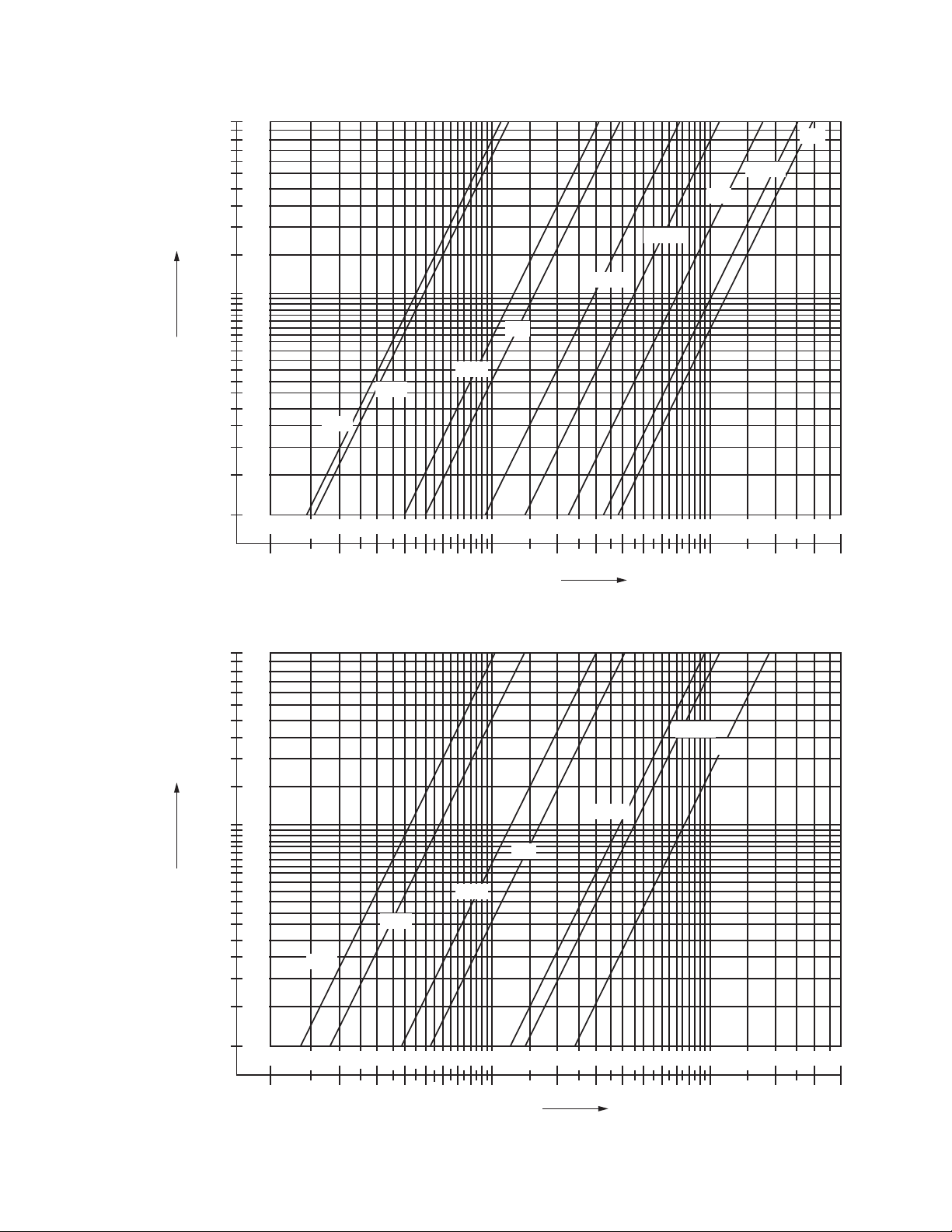
Valve capacities
Refer to Figures 1 and 2
Valve pattern
Straight through, non-offset
Body Material
Die cast aluminum
Electrical terminations
Screw terminal connections
Valve opening time
Less than 1 second
65-0194-04
Page 2
V4295A,S; V8295A,S SOLENOID GAS VALVES
Valve closing time
Current draw
Less than 1 second
Maximum operating pressure
3/8 in. through 3 in. pipe sizes: 2 psi
3/8 in. through 2 in. pipe sizes: 5 psi
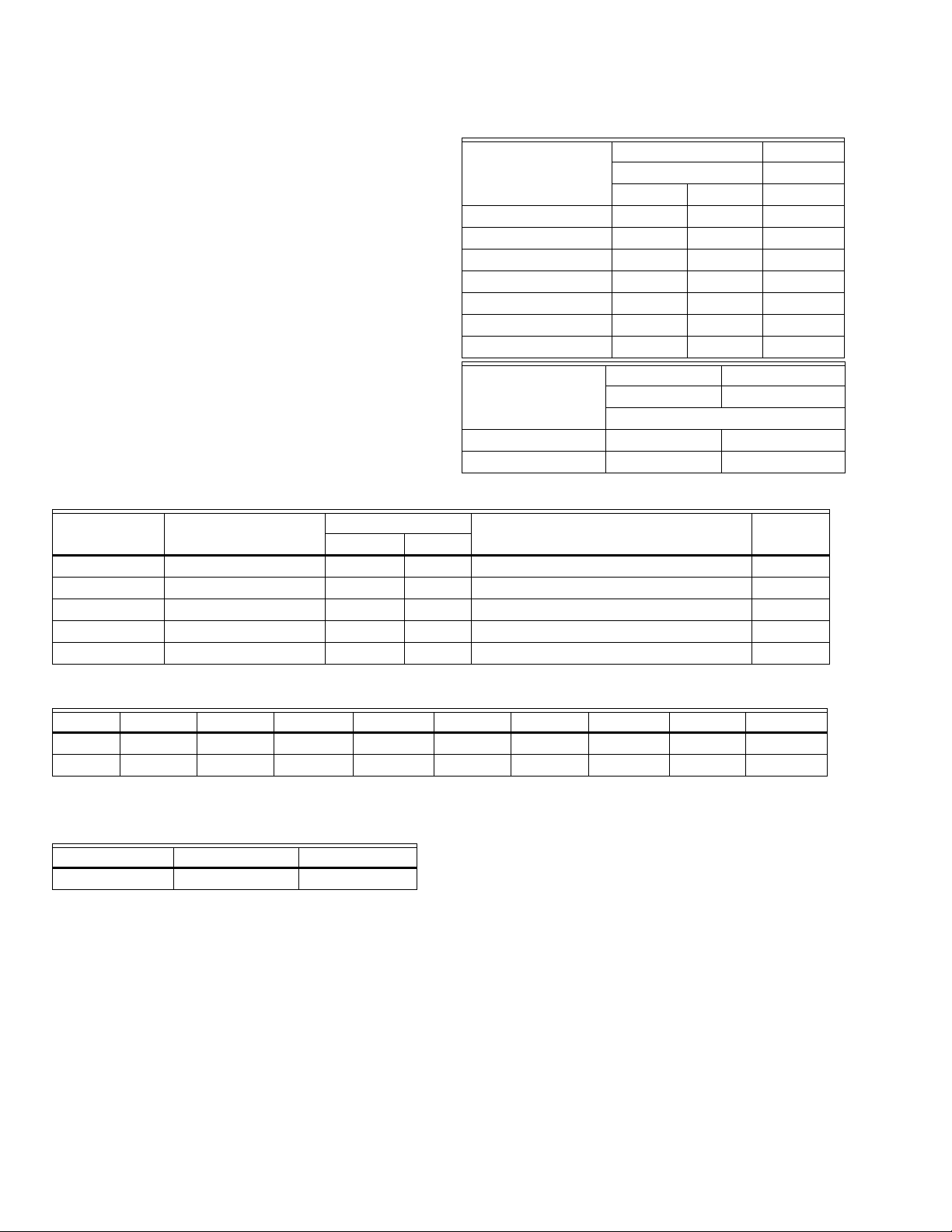
Normally Closed (N.C.)
Pipe size (inch)
V4295A V8295A
120 Vac 24 Vac
2 psi 5 psi 2 psi
3/8 and 1/2 0.160 A 0.160 A 0.80 A
3/4 and 1 0.160 A 0.200 A 0.80 A
1-1/4 0.340 A 0.550 A 1.60 A
1-1/2 0.300 A 0.550 A 1.70 A
2 0.525 A 0.540 A 2.80 A
2-1/2 0.575 A n/a n/a
3 0.675 A n/a n/a
Normally Open (N.O.)
Pipe size (inch)
V4295A V8295A
120 Vac 24 Vac
2 psi
3/4 and 1 0.160 A 0.80 A
1-1/4 0.340 A 2.40 A
Table 1. Models Available.
Model Voltage/Frequency
Maximum Pressure
Pipe size (inch)
Thread
typepsi mbar
V4295A (N.C.) 110/120 Vac, 50/60 Hz 2.0 140 3/8, 1/2, 3/4, 1, 1-1/4, 1-1/2, 2, 2-1/2, 3 NPT
V4295A (N.C.) 110/120 Vac, 50/60 Hz 5.0 350 3/8, 1/2, 3/4, 1, 1-1/4, 1-1/2, 2 NPT
V4295S (N.O.) 110/120 Vac, 50/60 Hz 2.0 140 3/4, 1, 1-1/4 NPT
V8295A (N.C.) 24 Vac, 50/60 Hz 2.0 140 3/8, 1/2, 3/4, 1, 1-1/4, 1-1/2, 2 NPT
V8295S (N.O.) 24 Vac, 50/60 Hz 2.0 140 3/4, 1, 1-1/4 NPT
Table 2. Capacity in CFH at Pressure Drop of 1-Inch Water Column sp. gr. = 0.64 for V4295A, V8295A (N.C.).
3/8 in. 1/2 in. 3/4 in. 1 in. 1-1/4 in. 1-1/2 in. 2 in. 2-1/2 in.* 3 in.*
2 psi 230 250 645 790 1,450 2,190 3,465 5,070 6,100
5 psi 210 290 610 825 1,950 2,270 3,740 n.a. n.a.
* V4295A only
Table 3. Capacity in CFH at Pressure Drop of 1-Inch
Water Column sp. gr. = 0.64 for V4295S, V8295S (N.O.).
3/4 in. 1 in. 1-1/4 in.
350 420 1,100
65-0194—04 2
Page 3
6
24
520
4
16
3
12
V4295A,S; V8295A,S SOLENOID GAS VALVES
3 IN.
2-1/2 IN.
2 IN.
28
1
4
0.8
3.2
∆ P (KPA)
∆ P (IN. W.C.)
0.6
2.4
0.5
0.4
0.3
0.2
0.1
2.0
1.6
1.2
1.0
0.8
0.4
1 2 3 4 5 6 8 10 20 30 40 50 60 80 100 200 300 400
3/8 IN.
1/2 IN.
3/4 IN.
1 IN.
1-1/4 IN.
X 100Vg (NATURAL GAS SG 0.64) (CFH) =
1-1/2 IN.
M28666
Fig. 1. Capacity curves for V4295A and V8295A, 2 psi versions.
6
24
520
4
16
3
12
28
1
4
0.8
3.2
∆ P (KPA)
∆ P (IN. W.C.)
0.6
2.4
0.5
0.4
0.3
0.2
0.1
2.0
1.6
1.2
1.0
0.8
0.4
3/8 IN.
1 2 3 4 5 6 8 10 20 30 40 50 60 80 100 200 300 400
1/2 IN.
3/4 IN.
1 IN.
1-1/4 IN.
X 100Vg (NATURAL GAS SG 0.64) (CFH) =
1-1/2 IN.
2 IN.
M28667
Fig. 2. Capacity curves for V4295A, 5 psi versions.
3 65-0194—04
Page 4

V4295A,S; V8295A,S SOLENOID GAS VALVES
Ambient temperature rating
-40ºF to 145ºF (-40ºC to 63ºC)
Maximum fluid temperature rating
-40ºF to 145ºF (-40ºC to 63ºC)
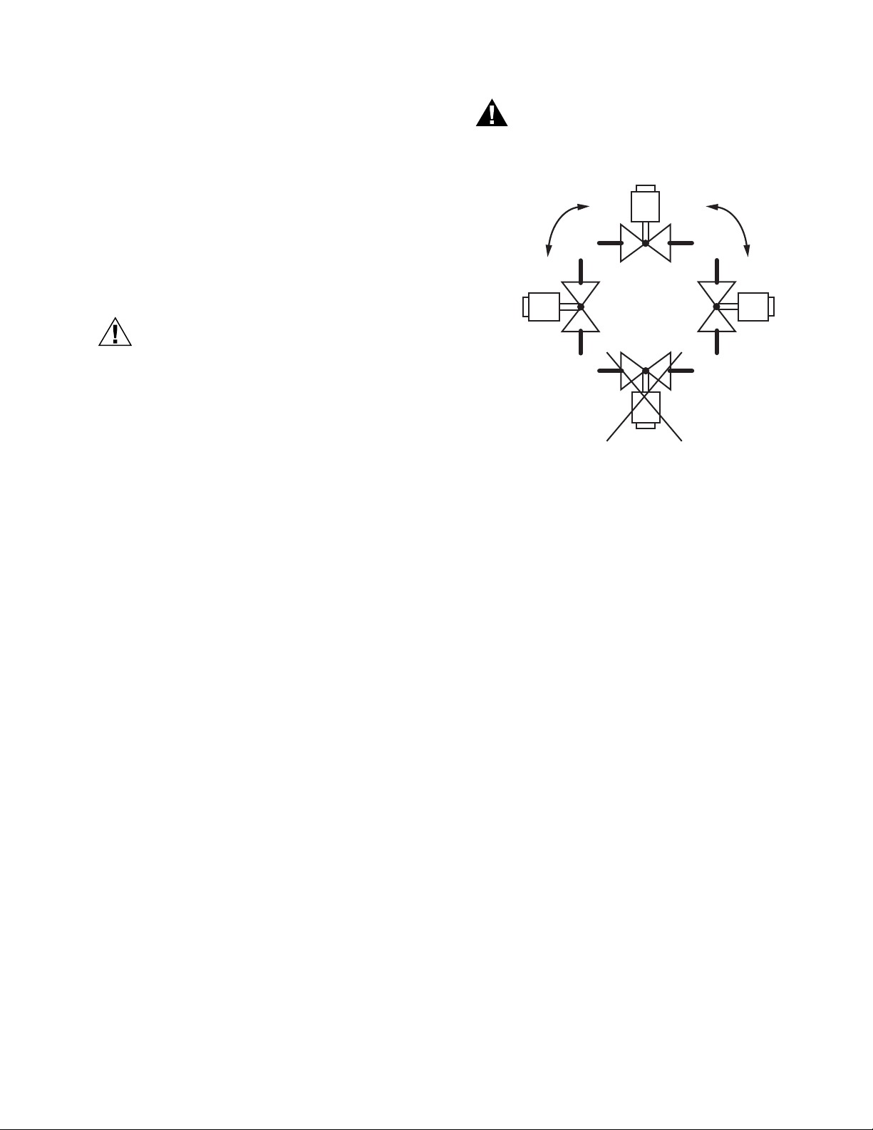
Mounting position
Vertical to 90 degrees from vertical, refer to Fig. 5.
Dimensions and weight
Refer to Figures 3 and 4.
D
C
E
Approvals
Underwriters Laboratories, Inc., File Number MH 18476,
Guide number YLOZ
AGA and CGA, File Number C2030014
Complies with standard ANSI Z21.21-CGA6.5
Automatic Valves for gas appliances and automatic safety
shut-off gas valves (revised edition of the former ANSI
Z21.21, CAN/CGA-6.5-M89, CAN/CGA-3.9-M87)
Factory Mutual:
V4/8295A: 2 psi rated, 3/8 in. to 3/4 in.
V4/8295A: 5 psi rated, 3/8 in. to 2 in.
V4/8295S: All
CSD-1 Acceptable.
D
C
B
B
E
A
M28661
Fig. 3. Dimensions (normally closed).
Fig. 4. Dimensions (normally open).
Table 4. Normally Closed (See Fig. 3).
Pipe size
3/8 in. NPT 2-7/8 4-7/16 4-7/16 2-3/16 2-3/16 3-3/4 3-3/4 2-3/16 2.5 2.2
1/2 in. NPT 2-7/8 4-7/16 4-7/16 2-3/16 2-3/16 3-3/4 3-3/4 2-3/16 2.5 2.2
3/4 in. NPT 3-7/16 5-1/4 5-13/16 2-3/16 2-1/2 3-3/4 4-1/16 2-3/4 4.0 4.4
1 in. NPT 3-15/16 5-1/4 6-5/16 2-3/16 2-1/2 3-3/4 4-1/16 3 4.5 4.4
1-1/4 in. NPT 5-15/16 8 8-9/16 2-1/2 3-5/16 4-1/16 4-15/16 4-3/8 12.8 10.6
1-1/2 in. NPT 5-15/16 8-3/8 8-9/16 3-3/8 3-5/16 4-15/16 4-15/16 4-3/8 12.8 10.6
2 in. NPT 6-11/16 8-3/8 9-3/16 3-3/8 3-3/4 4-15/16 5-5/16 5-3/8 14.0 13.4
2-1/2 in. NPT 9-1/2 12-3/4 — 4-9/16 — 6-1/8 — 7-7/8 28.5 —
3 in. NPT 9-1/2 12-3/4 — 4-9/16 — 6-1/8 — 7-7/8 31.0 —
Pipe size A (inch) B (inch) C (inch) D (inch) E (inch) (both sides) Weight (lbs)
3/4 in. NPT 3-7/16 5-1/2 2-3/16 3-3/4 2-3/4 4.0
1 in. NPT 3-15/16 5-1/2 2-3/16 3-3/4 3 4.5
1-1/4 in. NPT 5-15/16 8-3/4 2-1/2 4-1/16 4-3/8 12.8
A
(inch)
B (inch) C (inch) D (inch)
2 psi 5 psi 2 psi 5 psi 2 psi 5 psi 2 psi 5 psi
Table 5. Normally Open (See Fig. 4).
A
E (inch)
(both sides)
M28662
Weight (lbs)
65-0194—04 4
Page 5
INSTALLATION
CAUTION
WARNING
V4295A,S; V8295A,S SOLENOID GAS VALVES
When installing this product...
1. Read this instructions carefully. Failure to follow them
could damage the product or cause a hazardous condition.
2. Check the rating given in the instructions and on the
product to make sure the product is suitable for your
application.
3. Installer must be a trained, experienced, flame safeguard control technician.
4. After installation is complete, check out product operation as provided in these instructions.
1. Turn off gas supply before starting installation.
2. Disconnect power supply before beginning
installation to prevent electrical shock and
equipment damage.
3. Do not remove seal over valve inlet or outlet
until ready to connect piping.
Prepare piping and install valve (Fig. 5)
1. Use new, properly reamed pipe which is free from chips.
2. Do not thread pipe too far.
3. Apply good quality pipe dope resistant to the action of
LP gas, putting a moderate amount on the male threads
only. If pipe dope lodges on the valve seat, it will prevent
proper closure.
4. Install valve in a horizontal pipe line, (refer to Fig. 5 for
mounting position) with the gas flow matching the direction indicated by the arrow on the casting.
5. Apply a parallel jaw wrench only to the wrench flats of
the valve body, next to the pipe being inserted. A
wrench applied to the valve body itself or to the end farthest from the pipe being inserted may distort the casting, resulting in malfunction on the gas valve.
6. The gas flow must be in the same direction as the arrow
on the body of the valve.
If the flow is not in the same direction of arrow,
valve may not shut off.
M28663
Fig. 5. Mounting position.
7. Make electrical connections as illustrated in the wiring
diagrams; see Fig. 6.
8. Turn on main gas and with a soap solution, check valve
installation for leaks.
WIRING
1. Disconnect power supply before making wiring connec-
tions to prevent electrical shock and equipment damage.
2. Installation and wiring must be in conformance with
National Electrical Code ANSI/NFPA 70, local codes
and regulations.
3. For normal installations, use moisture-resistance No. 14
wire suitable for at least 167ºF (75ºC) if using a Flame
Safeguard Primary Control, or 194ºF (90ºC) if using a
Flame Safeguard Programming Control.
4. For high temperature installations, use moisture resistant No. 14 wire selected for a temperature rating above
the maximum operating temperature.
5. Check the power supply circuit. The voltage and frequency must match those of the valve.
6. Refer to Fig. 6 for typical V4295A,S field wiring with
RM7800 (typical) Primary Safety Control. Refer to Fig. 7
for typical V8295A,S field wiring with Primary Safety
Control. Follow the burner manufacturer’s wiring diagram, when provided. Refer to burner controller (primary safety control) wiring diagram for specific wiring
terminal designations.
7. Make wiring connections at the electrical terminations
provided in the wiring compartment of the valve.
5 65-0194—04
Page 6

V4295A,S; V8295A,S SOLENOID GAS VALVES
WARNING
CAUTION
M28664
120 VAC
GROUND
G
4
N
L
9
NEUTRAL
LINE
VOLTAGE
MAIN VALVE
V4295A,S
RM7800
(TYPICAL)
L2
M28665
LIMIT(S)
TRANSFORMER
L1
(HOT)
L2
V8295A,S
G
NL
24 VOLT
THERMOSTAT
FLAME
SAFEGUARD
CONTROL
POWER SUPPLY. PROVIDE DISCONNECT
MEANS AND OVERLOAD PROTECTION
AS REQUIRED.
CHECKOUT AND TROUBLESHOOTING
Do not allow fuel to accumulate in the combustion
chamber. If fuel is allowed to enter the chamber for
longer than a few seconds without igniting, an
explosive mixture could result.
1. Do not put the system into service until you
have satisfactorily completed all applicable tests
described in the Checkout section of the
instructions for the flame safeguard control and
any other test required by the burner
manufacturer.
2. Close all manual fuel shut off valves as soon as
trouble occurs.
CHECKOUT
Fig. 6. Wiring, V4295A,S.
Fig. 7. Wiring, V8295A,S.
OPERATION
The V4295A and V8295A Normally Closed series gas valves
are Class B fail safe shut off valves. The valve is opened by
energizing the direct ON/OFF operator. The direct ON/OFF
operator consists of a coil and stop sleeve assembly. Inside
the stop sleeve assembly is a plunger which is able to move
up and down, thus opening or closing the valve. The plunger
glides on two anti-friction bearings. A strainer, made of AISI
303 stainless steel, is incorporated into the valve.
65-0194—04 6
1. Check the performance of the valve by measuring the
pressures at the inlet and outlet pressure taps. The
pressure reading at the outlet tap may be slightly higher
than a downstream measurement due to dynamic gas
flow effects. The measurement at the outlet tap is for
reference only.
2. Shut off gas supply to valve and make sure valve is
closed when setting up pressure measuring equipment.
3. Set thermostat or controller to energize the valve and
check final outlet pressure.
4. Start the system and observe its operation through at
least one complete cycle to ensure the valve functions
as described in the section “Operation” on page 6.
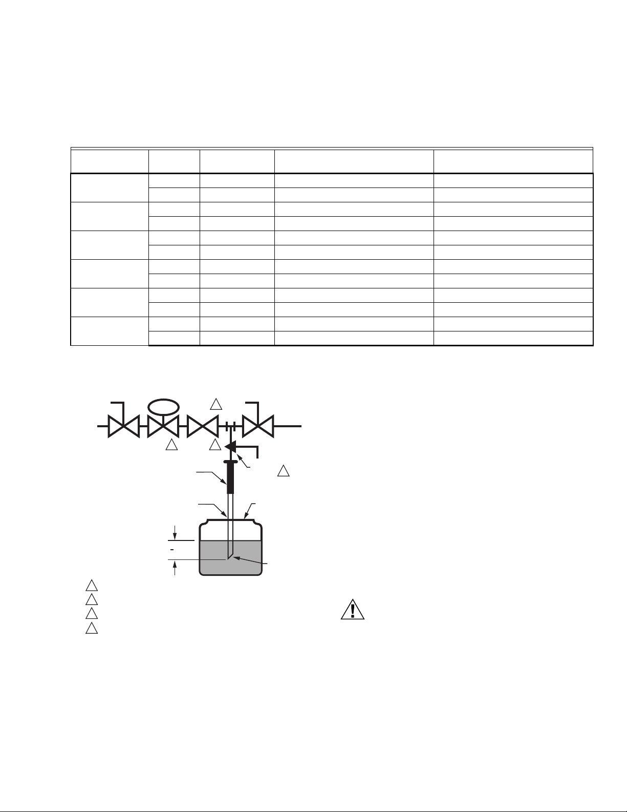
Valve Leak Test (Fig. 8)
This is a test for checking the closure tightness of the gas
safety shutoff valve. It should be performed only by trained,
experienced flame safeguard control technicians during the
initial startup of the burner system or whenever the valve is
replaced (see Service Information section). It is recommended
that this test also be included in the scheduled inspection and
maintenance procedures.
1. De-energize the control system to make sure no power
goes to the valve (C, Fig. 8).
2. Close the upstream manual gas cock (A).
3. Make sure the manual test petcock (F) is closed in the
leak test tap assembly (D).
4. Remove the leak test tap plug and connect the test
apparatus to the leak test tap (D).
5. Close the downstream manual gas cock (E).
6. Open the upstream manual gas cock (A).
7. Run the V4/8295A Valve to is open position (through the
safety system); then immediately de-energize the system to close the V4/8295A Valve.
8. Immerse a 1/4 in. (6 mm) tube vertically 1/2 in. (13 mm)
into a jar of water.
9. Slowly open the manual test petcock (F).
Page 7
V4295A,S; V8295A,S SOLENOID GAS VALVES
CAUTION
M9547F
GAS
SUPPLY
UPSTREAM
MANUAL
GAS COCK
DOWNSTREAM
MANUAL
GAS COCK
BURNER
DABC E
F
PRV
MANUAL
TEST
PETCOCK
SSOV
1/4 IN. (6 MM)
FLEXIBLE
TUBING
1/4 IN. (6 MM)
ALUMINUM OR
COPPER PILOT
TUBING
JAR OR GLASS
WITH WATER
CUT AT
45 DEGREE
ANGLE
CAN ALSO BE A PERMANENT PETCOCK.
PRV = PRESSURE REGULATING VALVE.
SSOV = SAFETY SHUTOFF VALVE.
USE ONLY ONE OF THE DOWNSTREAM TAPS ON THE SS0V.
1
2
3
4
4
2 3
1
1
2
(13 MM)
LEAK
TEST
TAP
10. When the rate of bubbles coming through the water stabilizes, count the number of bubbles appearing during a
ten-second period. Each bubble appearing represents a
IMPORTANT
To meet U.S. requirements, make sure leakage does
not exceed the rates in Table 6.
flow rate of 0.001 cfh.
Table 6. Valve Allowable Leakage Rate.
V4295A/V8295A
Pipe Size (in) Medium
Allowable
Leakage SCCH*
Maximum Number of Bubbles in 10
Seconds
3/8 & 1/2 0.64 gas 294 7 13
1.57 LP 188 4 20.4
3/4 & 1 0.64 gas 301 7 12.7
1.57 LP 192 5 19.9
1-1/4 & 1-1/2 0.64 gas 532 13 7.2
1.57 LP 341 8 11.2
2 0.64 gas 578 15 6.6
1.57 LP 370 9 10.3
1-1/2 0.64 gas 752 19 5.1
1.57 LP 481 12 8
3 0.64 gas 925 24 4.1
1.57 LP 592 15 6.5
* Based on air at standard conditions, test pressures provided by ANSI Z21.21.
Section 2.42 and a maximum of 235 cc/h per inch of seal-off diameter (not pipe size).
Minimum Number of Seconds for
10 Bubbles
NOTE: For international leak test requirements, contact the
Fig. 8. Valve leak test.
appropriate approval agency.
After the Test
1. Close the upstream manual gas cock (A).
2. Close the manual test petcock (F), remove the test
apparatus, and close the leak test tap (D).
3. Make sure the downstream manual gas cock (E) is
closed.
4. Open the upstream manual gas cock (A) and energize
the V4/8295A Valve through the safety system.
5. Test with rich soap and water solution to make sure
there is no leak at the leak test tap (D) or any pipe
adapter/valve mating surfaces.
6. De-energize the V4/8295A Valve (C).
7. Open the downstream manual gas cock (E).
8. Restore the system to normal operation. If two safety
shutoff valves are used, check each valve separately for
closure tightness.
TROUBLESHOOTING
Use utmost care during troubleshooting. Line
voltage is present at the actuator for V4295A,S and
present in controller circuits. Low voltage (24 Vac)
is present at the actuator for V8295A,S and
present in controller circuits.
IMPORTANT
Do not assume that the valve must be replaced until
all other sources of trouble have been eliminated.
7 65-0194—04
Page 8
V4295A,S; V8295A,S SOLENOID GAS VALVES
CAUTION
CAUTION
CAUTION
1. If the valve will not open when the thermostat or
controller is calling for heat:
a. Check that there is voltage at the valve actuator
lead wires or terminal block.
Line voltage (120 Vac) should be present when the
primary safety control energizes the V4295A,S
valve actuator. 24 Vac should be present when the
primary safety control energizes the V8295A,S
valve actuator.
b. If there is no voltage at the actuator, first ensure line
voltage power is connected to the master switch, the
master switch is closed and overload protection (circuit breaker, fuse or similar device) has not opened
the power line.
c. If there is still no voltage at the actuator, make sure
all appropriate contacts in the thermostat (or controller), limit(s) and flame safeguard control are closed.
If one or more are open, determine the cause(s) and
correct condition(s) before proceeding.
d. If there is proper voltage at the actuator but the
valve still does not open, first check that the gas
pressure is normal.
e. If the valve still does not open, replace valve.
2. If the valve will not close when one or more of the
appropriate contacts in the thermostat (or controller), limit(s) or flame safeguard control is open:
a. Make sure that the gas flow is in the direction of the
arrow on the valve body.
b. Make sure the valve actuator is wired in the correct
circuit. Open the master switch to remove power
from the actuator. If the valve closes now, the actuator may not be wired properly.
c. Look for a short in the electrical circuit.
SERVICE INFORMATION
1. Only qualified service technicians should
attempt to service or repair flame safeguard
control and burner.
2. Line voltage is present in the electrical circuits
to the valve. Open the master switch before
replacing the valve.
1. Label all wires prior to disconnection when
servicing valves. Wiring errors can cause
improper and dangerous operation.
2. Verify proper operation after servicing.
Scheduled inspection and maintenance
For periodic inspection and maintenance, set up a schedule
and follow it. Include the burner, valves and all other burner
controls. It is recommended that “Valve Leak Test (Fig. 8)” on
page 6 be included in the schedule. Refer to the flame
safeguard control instructions for more information.
Automation and Control Solutions
Honeywell International Inc. Honeywell Limited-Honeywell Limitée
1985 Douglas Drive North 35 Dynamic Drive
Golden Valley, MN 55422 Toronto, Ontario M1V 4Z9
customer.honeywell.com
® U.S. Registered Trademark
© 2009 Honeywell International Inc.
65-0194—04 M.S. Rev. 02-09
 Loading...