

Page 1
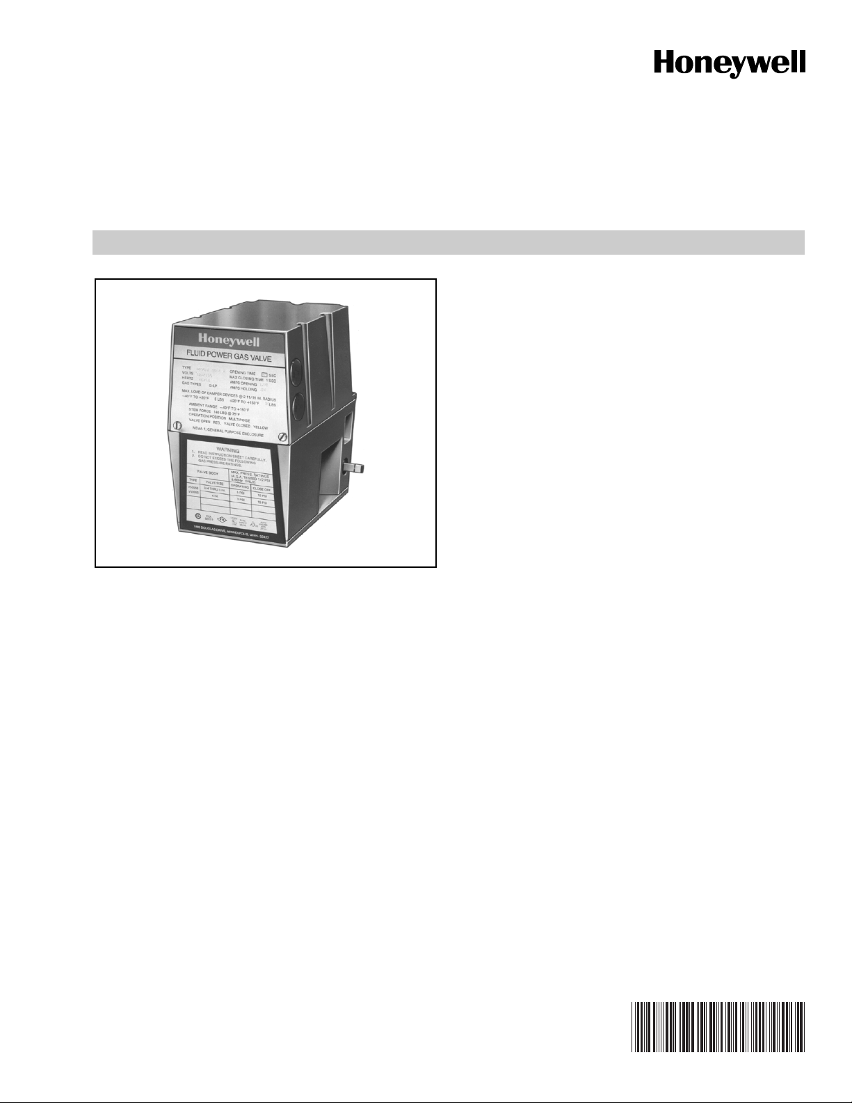
V4062A,B,D HI-LO-OFF Fluid Power
Gas Valve Actuator
PRODUCT DATA
APPLICATION
The V4062 Gas Valve Actuator in combination with a V5055,
VE5000
of the gas supply to commercial and industrial burners.
a
or V5097 Gas Valve provides three-position control
FEATURES
• When energized, the V4062 Actuator opens the V5055/
VE5000/V5097 Gas Valve to the low-fire position. The
actuator opens the valve to the fully open position
when the line voltage contacts are made.
a
VE5000 is a European manufactured and approved valve for
European use only.
• When used with the V5055, V5097 or VE5000
Valve, the combination is rated for final safety shutoff
service. Although the V4062 can be used with all V5055
or V5097 Valve models, the V5055/V5097B with
characterized guide is recommended for optimum
control and low-fire repeatability.
• The standard model has an opening time of
26 seconds at 60 Hz, or 32 seconds at 50 Hz. A
fast-opening model is available, with timings of
13 seconds at 60 Hz, or 16 seconds at 50 Hz.
• Maximum closing time is one second, which meets
code, standard, insurer requirements.
• Damper shaft models are available with or without
spring return; shaft extends out both sides and rides in
Delrin bushings; used with standard damper crank arm
(part no. 7616BR).
• Red OPEN indicator attached to the actuator stem
shows when the valve is even slightly open; yellow
SHUT indicator on the valve stem shows only when
the gas valve is fully closed.
• Ambient temperature range is -40° to 150°F (-40° to
66°C) for 60 Hz models; -10° to 158°F (23° to 70°C) for
50 Hz and 50/60 Hz models.
• Models available with factory adjusted, fieldadjustable, single-pole-double throw (spdt) auxiliary
switch rated at 1/2 hp (0.37 kW). Auxiliary switch can
be added in the field.
• Low-fire position is adjustable with adjusting wrench,
part no. 135796 (included with the actuator).
• Standard enclosure meets NEMA 1 (IP30) general
purpose requirements.
• V4062/V5055C,E and V4062/V5097C,E combinations
available with a proof-of-closure switch and double
valve seal (valve seal overtravel interlock) to meet
specific code/standard/insurer requirements.
• Model available to be used with series 60 floating type
controller.
• Model available with adjustable maximum flow switch.
a
Gas
Contents
Application ........................................................................ 1
Features ........................................................................... 1
Specifications ................................................................... 2
Ordering Information ........................................................ 2
Installation ........................................................................ 4
Wiring ............................................................................... 5
Adjustments ...................................................................... 6
Operation .......................................................................... 7
Service and Checkout ...................................................... 7
60-2099-10
Page 2

V4062A,B,D HI-LO-OFF FLUID POWER GAS VALVE ACTUATOR
SPECIFICATIONS
IMPORTANT:
The specifications given in this publication do not
include normal manufacturing tolerances. Therefore,
this unit may not exactly match the listed
specifications. Also, this product is tested and
calibrated under closely controlled conditions, and
some minor differences in performance can be
expected if those conditions are changed.
Models:
V4062A HI-LO-OFF Gas Valve Actuator.
V4062B HI-LO-OFF Gas Valve Actuator, high pressure.
V4062D HI-LO-OFF Gas Valve Actuator with proof-of-closure
switch. Use with V5055/V5097C,E (double seal) gas
valves for valve seal overtravel interlock. Do not use V4062
a
b
Fast-opening V4062B Actuators (Table 3):
Table 2. Fast-opening V4062A,D Actuators.
Opening Holding
Voltage/Frequency
WVAWVA
120V/60 Hz 59.5 129 19.0 28.0
220V/50 Hz 84.0 196 17.0 27.0
220V/50 Hz 82.0 180 16.5 26.4
a
220V-240V; 50-60 Hz
220V-240V; 50-60 Hz
74.5 143.5 13.7 24.8
b
61.9 112 11.2 20.5
230V, 50 Hz power supply.
230V, 60 Hz power supply.
60 Hz, 13 second opening.
50 Hz, 16 second opening.
with V5034 Valve body.
Electrical Ratings:
Standard V4062A,D Actuators (Table 1):
60 Hz, 26 second opening.
50 Hz, 32 second opening.
Table 1. Standard V4062A,D Actuators.
Vol tag e /
Frequency
Opening Holding
WVAWVA
120V/60 Hz 59.5 129 19.0 28.0
100V/50-60 Hz 53.0/42.7 105/80 20.0/17.2 33/29
200V/50-60 Hz 72.01/52.5 160/110 18.4/16.2 28/24
Fast-opening V4062A,D Actuators (Table 2):
220V-240V; 50-60 Hz
220V-240V; 50-60 Hz
a
230V, 50 Hz power supply.
b
230V, 60 Hz power supply.
Pressure Ratings Of Valve-Actuator Combinations:
Auxiliary Switch And Proof-Of-Closure Switch Ratings:
Table 3. Fast-opening V4062B Actuators.
Opening Holding
Voltage/Frequency
WVAWVA
a
76.5 150.6 13.3 28.8
b
64.4 118.2 11 23.2
See Table 4.
See Table 5.
60 Hz, 13 second opening.
50 Hz, 16 second opening.
Table 4. Pressure Ratings of Valve-Actuators Combinations.
Val ve
V4062A,D Actuator
Differential
b
a
Closeoff
c
psi mbar psi bar psi mbar psi bar
V4062B Actuator
Differential
b
Closeoff
c
V5055A,C; V5097A,C 3/4 to 3 in. 5 340 15 1 15 1000 15 1
V5055A,C 4 in. 3 200 15 1 5 340 15 1
V5055B, V5097B 3/4 to 3 in. 5 340 15 1 15 1000 15 1
V5055B 4 in. 3200515340151
V5055D,E, 3/4, 1, 1-1/4, 1-1/2; V5097D 3/4 in. to 2 in. 5 340 75 5 25 1700 75 5
V5055D,E; V5097D,E 2, 2-1/2, 3 in. 5 340 45 3 15 1000 45 3
a
Use a V4062D (with proof-of-closure switch) with a V5055/V5097C or E (with double seal) for valve seal overtravel interlock.
b
Maximum operating pressure differential.
c
Maximum closeoff pressure without seal leakage. This is the maximum allowable pressure drop to which a valve may be
subjected when fully closed, and is independent of the valve body rating.
ORDERING INFORMATION
When purchasing replacement and modernization products from your TRADELINE® wholesaler or distributor, refer to the
TRADELINE® Catalog or price sheets for complete ordering number.
If you have additional questions, need further information, or would like to comment on our products or services, please write or
phone:
1. Your local Honeywell Automation and Control Products Sales Office (check white pages of your phone directory).
2. Honeywell Customer Care
1885 Douglas Drive North
Minneapolis, Minnesota 55422-4386
In Canada—Honeywell Limited/Honeywell Limitée, 35 Dynamic Drive, Toronto, Ontario M1V 4Z9.
International Sales and Service Offices in all principal cities of the world. Manufacturing in Australia, Canada, Finland, France,
Germany, Japan, Mexico, Netherlands, Spain, Taiwan, United Kingdom, U.S.A.
60-2099—10 2
Page 3
V4062A,B,D HI-LO-OFF FLUID POWER GAS VALVE ACTUATOR
Table 5. Auxiliary Switch and Proof-of-Closure
Switch Ratings (1/2 hp [0.37 kW]
a
).
Load 120/v 240V
Full Load 9.8A 4.9A
Locked Rotor 58.8A 29.4A
a
Maximum total connected power to both switches (if used)
is 1800 VA.
Mounting:
Mounts directly to V5055/V5097 Valve with two setscrews posi-
tioned 90 degrees apart.
Valve and actuator can be mounted in any position
(multipoise).
NOTE: 220 to 240 Vac, 50/60 Hz models must be mounted
vertically.
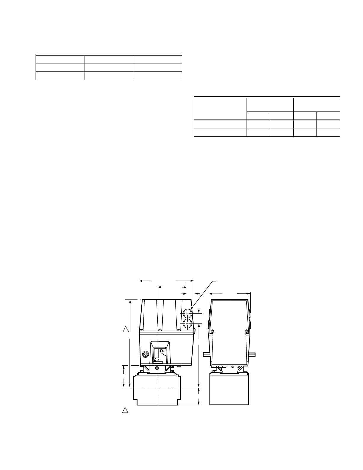
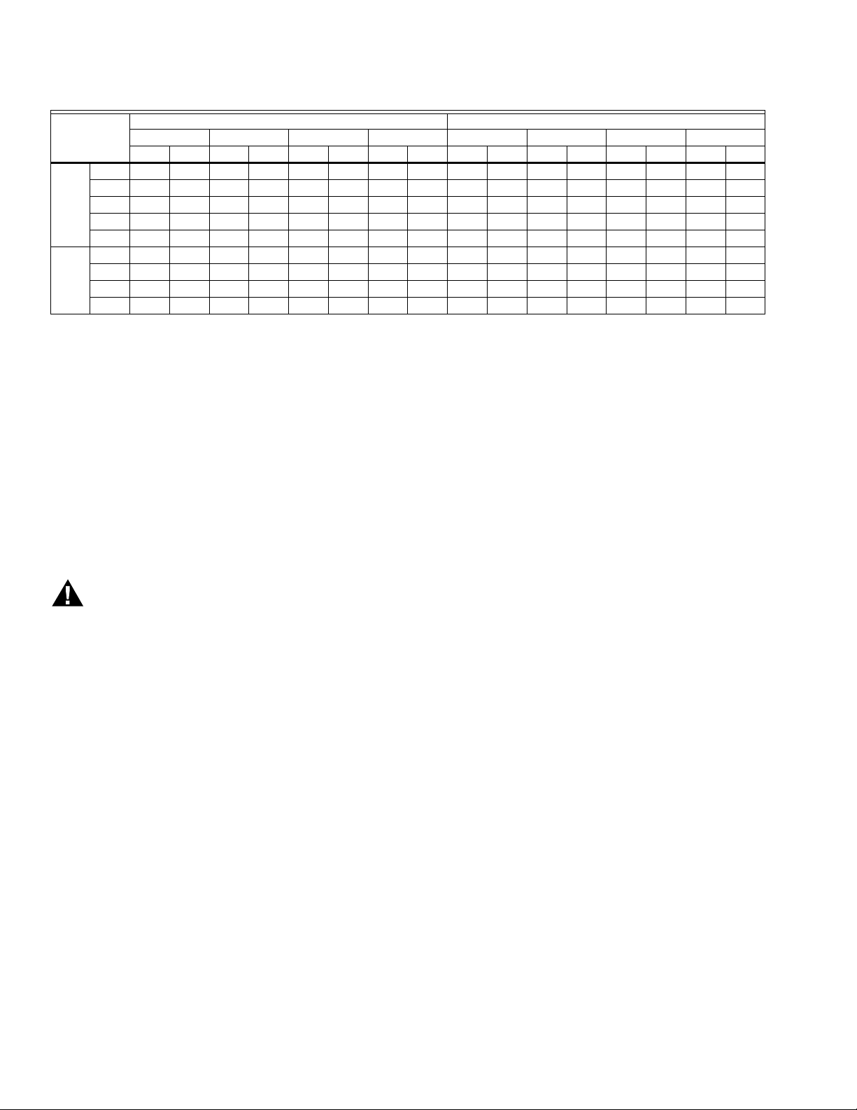
Mounting Dimensions: See Fig. 1 and Table 7.
Low-Fire Adjustment: 0.17 inch to 0.64 inch (with respect
to V5055/V5097B Valve) valve stem travel.
NOTE: The low-fire position of the V5055/V5097A,C,D and E
Valves differ from the V5055/V5097B. Check the
valve flow curves and match the low-fire position to
the burner design and valve application.
Nominal Opening Time:
Standard Models: 26 sec at 60 Hz; 32 sec at 50 Hz.
Fast-opening Models: 13 sec at 60 Hz; 16 sec at 50 Hz.
Closing Time: 1 sec maximum
Damper Shaft: 3/8 in. sq (9.5 mm) for use with 7616BR
Damper Crank Arm (not included). Models available with or
without damper shaft return spring.
Maximum Damper Shaft Rotation: 52 angular degrees.
Maximum Force: At 2-11/16 in. (68.3 mm) radius for 7616BR
Damper Crank Arm (ordered separately).
NOTE: Damper shaft drives damper crank arm in one
direction only; optional return spring is available on
damper shaft to turn damper crank arm in opposite
direction. See Table 6.
Table 6. Actuator Torque (With
and Without Return Spring).
V4062 Model
-40°F to +20°F
(-40°C to -7°C)
lb N lb N
20°F to 150°F
(-7°C to +66°C)
Without return spring 5 22.2 20 89.0
With return spring 5 22.2 10 44.5
Ambient Operating Temperature Rating:
-40° to 150°F (-40° to 66°C) for 60 Hz models;
-10° to 158°F (-23° to 70°C) for 50 Hz and 50/60 Hz models.
Approvals:
Underwriters Laboratories Inc. Listed: File No. MH1639, Guide
No. YIOZ.
Factory Mutual: Approved.
International Approval Services (Joint Venture of the American
Gas Association [AGA] and the Canadian Gas Association
[CGA]): Certified 60 Hz models only.
Industrial Risk Insurers Acceptable.
Some V4062 Actuators are approved as Class A valves in
accordance with EN161:
When used with V5055 Valves: Pin: CE-0063AR1359.
When used with VE5000 Series Valves: Pin:
CE-0063AP3075.
Accessories:
133568 Auxiliary Switch Bag Assembly.
133569 Proof-of-Closure Switch Bag Assembly. (Must be used
with a V5055/V5097C or E with double seal).
135796 Wrench (included with the actuator).
7616BR Damper Crank Arm (damper arm and clip).
6-3/4 (172)
3-23/32 (95)
27/32 (21)
1-9/32
(33)
1
A
C
B
VALV E
1
ALLOW 4 INCH (102 MM) CLEARANCE FOR ACTUATOR REMOVAL. M17755
D
KNOCKOUT FOR
1/2 INCH CONDUIT (4)
5 (127)
VALV E
Fig. 1. Approximate mounting dimensions of V4062 Actuators in in. (mm).
3 60-2099—10
Page 4
V4062A,B,D HI-LO-OFF FLUID POWER GAS VALVE ACTUATOR
Table 7. Approximate Mounting Dimensions of V4062 Actuators with V5055 and V5097 Valves.
V5055 V5097
Dim. A Dim. B Dim. C Dim. D Dim. A Dim. B Dim. C Dim. D
Val ve S izea (in.)
Small
3/4 11-1/8 283 2-3/4 70 8-3/16 208 5-3/4 146 11-1/8 283 2-3/4 70 8-3/16 208 2-1/2 64
Body
1 11-1/8 283 2-3/4 70 8-3/16 208 5-3/4 146 11-1/8 283 2-3/4 70 8-3/16 208 2-/12 64
1-1/4 11-1/8 283 2-3/4 70 8-3/16 208 5-3/4 146 11-1/8 283 2-3/4 70 8-3/16 208 2-1/2 64
1-1/2 11-1/8 283 2-3/4 70 8-3/16 208 5-3/4 146 11-1/8 283 2-3/4 70 8-3/16 208 2-1/2 64
2 11-1/8 286 2-7/8 73 8-5/16 211 8-3/8 213 11-3/4 298 3-3/8 86 8-3/8 213 4 102
Large
2 11-3/4 298 3-3/8 86 8-13/16 224 9-1/4 235 11-3/4 298 3-3/8 86 8-3/8 213 4 102
Body
2-1/2 11-3/4 298 3-3/8 86 8-13/16 224 9-1/4 235 11-3/4 298 3-3/8 86 8-3/8 213 4 102
3 11-3/4 298 3-38 86 8-13/16 224 9-1/4 235 11-3/4 298 3-3/8 86 8-3/8 213 4 102
4 14-1/83595-13/1614811-7/3228512-1/2318————————
a
Valve size using accessory pipe adapter fitting.
in.mmin.mmin.mmin.mmin.mmin.mmin.mmin.mm
INSTALLATION
When Installing This Product…
1. Read these instructions carefully. Failure to follow
them could damage the product or cause a hazardous
condition.
2. Check the ratings given in the instructions and on the
product to make sure the product is suitable for your
application.
3. Installer must be a trained experienced, flame
safeguard control technician.
4. After installation is complete, check out product
operation as prided in these instructions.
WARNING
Electrical Shock Hazard.
Can cause serious injury or death.
Disconnect power supply before making wiring
connections to prevent electrical shock and
equipment damage.
IMPORTANT
1. All wiring must comply with all applicable electrical codes,
ordinances, and regulations. All wiring must be NEC
Class 1.
2. Voltage and frequency of the power supply connected to
this control must agree with those marked on the device.
3. Loads connected to the auxiliary switch and/or
proof-of-closure switch, if used, must not exceed the
ratings given in the Specifications section.
4. When replacing a V6034 Actuator with a V4062, the
V5034 Valve body must be changed to a V5055 Valve.
5. Do not attempt to use the V4062 Actuator with the V4055/
V5034 Adapter. Differences in stem travel can prevent
correct low fire adjustment.
Install Valve
The actuator is installed directly on the V5055/V5097 body
after the valve is installed in the gas supply line. Refer to the
instructions packed with the V5055/V5097 Gas Valve for
installation details. When installing the valve, assure that:
1. Sufficient clearance is allowed for actuator installation
and service.
2. Ambient temperatures at the valve location do not
exceed actuator ratings.
3. Position of the valve permits damper hookup if one is
controlled.
Install Accessory Switches (If Needed)
An spdt switch can be installed to operate an auxiliary load up
to 1/2 hp (0.37 kW). The switch can be adjusted to operate at
any point in the valve stroke.
A proof-of-closure switch can also be installed with a V5055/
V5097C or E Valve (with double seal) on any V4062 Actuator
to provide a valve seal overtravel interlock. The spdt proof-ofclosure switch is installed to make or break a circuit when the
valve is in the closed position. The switch is not adjustable.
NOTE: Mark the actuator or valve to indicate any changes
made.
To install the switches, proceed as follows:
1. Remove the actuator faceplate (two screws).
2. Remove the silver-colored barrier to expose the actuator
stem.
3. Insert the auxiliary switch in the position indicated in Fig.
2. Fasten with two screws through the actuator base.
4.
Insert the proof-of-closure switch in the position shown in
Fig. 2. The proof-of-closure switch mounts against the side
of the actuator housing. The mounting holes are spaced to
allow mounting the switch only in the correct position.
Fasten with two screws through the actuator base.
5. If only one switch is used, install the narrow barrier
included with the switch in the unused space.
6. Mount the actuator before making wiring connections
and adjustments to the auxiliary switch.
60-2099—10 4
Page 5
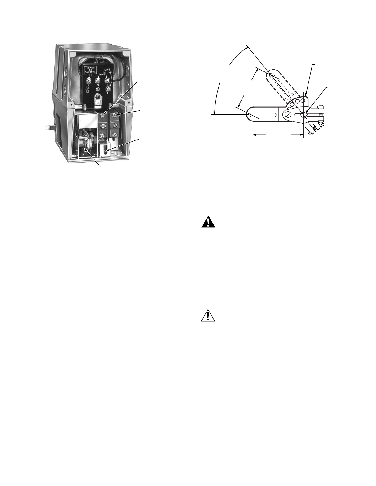
133568
AUXILIARY
SWITCH
133569
VALVE-CLOSED
INDICATION
SWITCH
V4062A,B,D HI-LO-OFF FLUID POWER GAS VALVE ACTUATOR
7616BR
52 DEGREE
ANGULAR
ROTATION
2-5/16 (58.7)
MAXIMUM
TRAVEL
DAMPER
ARM
SHAFT
AUXILIARY
SWITCH
ADJUSTMENT
SCREW
LOW-FIRE
ADJUSTMENT CAM
M7338B
Fig. 2. V4062 Actuator with cover removed.
Mount Actuator On Valve
Check the final position of the V5055/V5097 Valve body to be
sure that the actuator will be in the proper position when
mounted on the valve. This is especially important when the
actuator is used to drive a damper.
If two smaller size valves are mounted very close together, as
in an Industrial Risk Insurers type valve train, it may be
necessary to mount the actuators off center to provide
adequate clearance.
Slip the bottom collar of the actuator over the valve bonnet
assembly. Rotate the actuator to the desired position and use a
5/32-inch Allen wrench to securely tighten the two setscrews
(50 to 60 lb-in. [5.7 to 6.8 N•m]). Connect the damper linkage, if
used. Refer to the instructions packed with the damper crank
arm.
Mount and Adjust 7616BR Damper Crank Arm (If Used)
The damper crank arm provides a maximum travel of
2-5/16 in. (58.7 mm) through a stroke of 52 degrees.
See Fig. 3. If the V4062 has a damper shaft return spring,
dampers go to the closed position when power is interrupted
by the programmer. Refer to the instructions packed with
the 7616BR Damper Crank Arm for complete installation
information.
2-11/16 (68.3)
RADIUS
M7322
Fig. 3. 7616BR Damper Crank Arm can be attached to
actuator shaft to drive a damper at same time valve is
opened.
WIRING
Wiring must comply with all applicable electrical codes,
ordinances, and regulations. Wiring to the actuator and to
the controller must be NEC Class 1.
WARNING
Electrical Shock Hazard.
Can cause serious injury or death.
Disconnect power supply before doing any wiring.
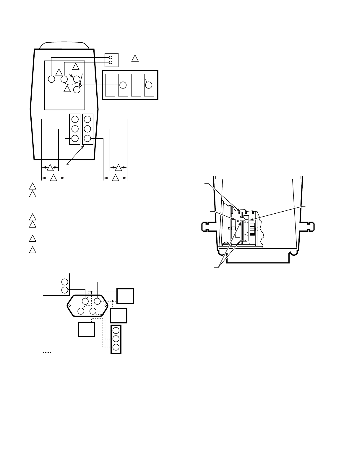
Connect the power from the flame safeguard control to
terminals 1 and 2 on the V4062 terminal strip, and connect the
firing rate controller to terminals 3 and 4. Refer to Fig. 4 for
typical connection. Fig. 5 shows the wiring for connecting the
Max Flow Limit Switch to the actuator. For other typical system
hookups, refer to the instructions packed with the device used
to control the valve. When all wiring connections are complete,
replace the actuator faceplate.
CAUTION
Equipment Damage Hazard.
Can cause equipment damage or improper and
dangerous operation.
Label all wires prior to disconnection when servicing
valves. Wiring errors can cause improper and
dangerous operation.
5 60-2099—10
Page 6
V4062A,B,D HI-LO-OFF FLUID POWER GAS VALVE ACTUATOR
FIRING
2
RATE
1
L1
HOT L2
4
34
AUXILIARY
SWITCH
5
6
1
POWER FROM FLAME SAFEGUARD CONTROL.
ACTUATOR OPENS TO LOW-FIRE POSITION WHEN FIRING RATE
2
CONTROLLER SWITCH IS OPEN AND LINE VOLTAGE IS SUPPLIED
TO TERMINALS L1 AND L2. ACTUATOR OPENS FULLY WHEN THE
FIRING RATE CONTROLLER SWITCH IS CLOSED AND POWER IS
SUPPLIED TO TERMINALS L1 AND L2.
INTERNAL JUMPER.
3
FOR LOW-FIRE ADJUSTMENT AFTER BURNER IS IN OPERATION.
4
DISCONNECT FIRING RATE CONTROLLER LEADWIRE FROM
TERMINAL 4.
SWITCH BETWEEN THESE TWO LEADS IS CLOSED WHEN VALVE IS
5
SHUT (DE-ENERGIZED).
SWITCH BETWEEN THESE TWO LEADS IS OPEN WHEN VALVE IS
6
SHUT (DE-ENERGIZED).
1
3
2
C
C
NC
NC
NO
NO
PROOF-OFCLOSURE SWITCH
CONTROLLER
L2
FLAME SAFEGUARD
PROGRAMMER–MAIN
VALVE CONNECTIONS
5
6
M7339
Fig. 4. Typical hookup for V4062 Actuator.
7800 SERIES
RELAY
MODULE
L2
9
34
TRAVEL
LIMIT
SWITCH
FIELD WIRING
INTERNAL WIRING
PUMP
1
2
VALVE
PUMP
MOTOR
NO
NC
C
ADJUSTABLE
MAX
FLOW
LIMIT
SWITCH
M12798
Fig. 5. Connecting Max Flow Limit Switch to the actuator.
ADJUSTMENTS
independent; the same setting applies to both. The low-fire
setting is adjusted either before the actuator is installed or after
the entire system is operational. Refer to form 70-8311 for
valve flow (capacity) curves.
IMPORTANT:
When using the V4062 with a V5055/V5097C or E
Valve (with double seal), match low-fire minimum
position to burner and application. Too low a position
could result in loss of burner flame. This low-fire
position should also be checked at periodic
maintenance intervals.
For most effective use of the V4062/V5055 or V4062/V5097,
be sure to select a valve body size closely corresponding to
burner capacity. An oversized valve might not allow the
low-fire rate to be adjusted to the desired minimum setting.
The V4062 Actuator is shipped from the factory with the
low-fire setting at MAX to provide a valve gas flow of
approximately 50 to 60 percent, which is adequate for safe
lightoff until the final setting can be determined.
LOWFIRE
CAM
SETSCREW
DUAL
LOW-FIRE
SETPOINT
INDICATORS
(SHOWN AT
MAX WITH
VALVE OPEN)
MAX
MIN
MAX
E
D
C
B
LO FIRE
A
DIAL
M7340
Fig. 6. Low-fire position can be adjusted from 0.16 in. to
0.64 in. (with respect to V5055/V5097B) valve stem travel.
Recommended Procedure
To adjust the low-fire setting without energizing the actuator,
proceed as follows:
1. Remove the wiring compartment cover.
2. Manually rotate the cam and dial assembly downward so
that the setscrew is accessible from the front of the actuator.
3. Loosen the setscrew on the low-fire cam using the
special wrench (supplied—taped to the inside of the
actuator cover).
4. Set the cam to the predetermined low-fire setting for the
burner being used.
5. Tighten the setscrew in the cam.
6. Replace the wiring compartment cover.
Low-Fire Adjustment
The low-fire position is adjustable from 0.16 in. to 0.64 in. (with
respect to V5055/V5097B Valve) valve stem travel. A dial on
the low-fire cam (Fig. 6) indicates the low-fire setting. Because
the cam rotates as the valve opens, scales are marked on the
dial so the low-fire setting can be observed with the valve in
any position. One scale is visible when the actuator is closed,
and the other is visible when it is open. These scales are not
60-2099—10 6
Alternate Procedure
To adjust the low-fire setting after the burner is in operation,
use the following instructions:
1. Remove the wiring compartment cover.
2. Check to be sure the low-fire adjustment is set at MAX to
assure a safe lightoff. (Low-fire adjustment is preset at
the factory in the MAX position.)
Page 7

V4062A,B,D HI-LO-OFF FLUID POWER GAS VALVE ACTUATOR
3. Disconnect the firing rate controller leadwire from
terminal 4 on the actuator to keep the valve in the
low-fire position (Fig. 4).
4. Start the system and establish the main burner flame.
5. Loosen the setscrew in the cam (Fig. 5) with the special
wrench. Keep the wrench seated in the setscrew. Rotate
the cam slightly downward (by moving the wrench
toward the actuator base) to open the bleed valve. The
actuator will start to close.
6. When the valve reaches the desired low-fire position,
quickly tighten the setscrew and remove the wrench.
If the desired low-fire setting is missed, loosen the
setscrew and rotate the cam in the opposite direction to
the desired setpoint.
7. Shut down the burner, and then restart. Repeat several
times to be sure the low-fire setting is suitable for correct
burner lightoff. Readjust, if necessary.
8. Disconnect power and reconnect the controller leadwire
removed in step 3.
9. Replace the wiring compartment cover.
Adjust Auxiliary Switch (If Used)
The auxiliary switch can be adjusted to operate at any point in
the actuator stroke. After installing the switch in the actuator,
turn the adjustment screw (Fig. 2) clockwise to cause
the switch to operate earlier in the stroke or turn
counterclockwise to cause the switch to operate later
in the stroke.
NOTE: The proof-of-closure switch is not adjustable.
Adjust Max Flow Limit Switch (Fig. 2)
The Max Flow Limit Switch is adjustable throughout the actuator
stroke. With the switch installed in the actuator, turn the
adjusting screw clockwise to cause the switch to operate
earlier in the stroke (less flow) or counterclockwise to
cause the switch to operate later in the stroke (more flow).
OPERATION
To function as intended, the V4062 must be connected to a
properly sized valve. Too large a valve will not properly control
the gas flow.
When the actuator is energized, it drives to the adjustable lowfire position. Depending on the demand of the controller, the
valve remains at low-fire or moves to the high-fire position.
When the firing rate controller calls for no heat, the actuator
returns the valve to the low-fire position. When power to the
actuator is interrupted, the valve completely closes.
Fig. 4 shows the V4062 in a typical flame safeguard control
system.
SERVICE AND CHECKOUT
CAUTION
Equipment Damage Hazard.
Unskilled technicians can damage the equipment.
Only experienced, trained flame safeguard control
service technicians should service or replace this
control.
Service
The actuator is not field repairable, except for replacing the
auxiliary switch or valve-closed indication switch. See Installation
section for procedure. Do not disassemble the valve actuator. If
the actuator should fail to operate properly, replace it.
1. Turn off the gas supply at the manual shutoff valve
located upstream from the valve(s) being serviced.
2. Shut off all electrical power to the valve actuator(s).
3. Mark and disconnect the wires from the actuator termi-
nals. Remove conduit and disengage the damper linkage assembly (if applicable).
4. Loosen the two set screws from the valve to lift off the
actuator.
5. If the actuator is to be replaced and it did not leak
hydraulic fluid, skip to Step 11.
NOTE: It is good practice to inspect the inside of the
valve whenever the actuator is replaced. To do
so, remove the bonnet assembly, inspect the
valve and bonnet. If all is well, proceed to Step 7.
6. If the actuator leaked hydraulic fluid onto the valve (the
fluid is red), it must be cleaned off from the valve and
bonnet assembly.
a. Wipe off the outer valve body.
b. Remove the valve bonnet bolts and lift off the bonnet.
NOTE: V5055/V5097C and E Valves have additional
c. Inspect the inside of the valve.
IMPORTANT
d. If the inside surfaces are clear of hydraulic fluid, clean
7. If the valve bonnet assembly is in good condition and is
not replaced, replace the bonnet seal. Do not reuse the
old bonnet seal. See Table 9 below for the seal number.
8. Coat seals with grease provided and position in valve
body/bonnet assembly.
9.
Carefully seat the bonnet assembly on the valve body. Be
sure the seals are in their proper position. On those valves
with a spring below the disc, be sure the spring is centered
in the indentation on the inside of the valve body.
10. After positioning the bonnet assembly, replace the
screws removed earlier.
NOTE: When replacing the bonnet assembly on the 4-
3/4 in. (19 mm) to 1-1/2 in. (38 mm) 55 in.-lb.
2 in. (51 mm) to 4 in. (102 mm) 75 in.-lb.
internal springs that will push the bonnet up as
the bolts are loosened.
If fluid is present on the inside surfaces of the valve
body or bonnet surfaces, the bonnet assembly or
entire valve must be replaced. See Table 8 below for
the bonnet assembly part number.
the bonnet assembly and be sure to remove all
hydraulic fluid from the inside and outside of the actuator mounting curb. This is the “cup-like” area around
the valve stem. Avoid using a cleaning solution as it
may damage the rubber seals used in the valve.
inch valve, draw it evenly into the valve body.
Finger-tighten the eight bolts. Draw the bonnet
assembly into the valve by tightening, in order,
bolts 1, 5, 7 and 3 (two turns each). Repeat until
the bonnet assembly is seated. Tighten the
remaining bolts. Torque the bolts as follows:
Val ve Si ze Torque
7 60-2099—10
Page 8
V4062A,B,D HI-LO-OFF FLUID POWER GAS VALVE ACTUATOR
11. Remount the actuator on the bonnet assembly. Tighten
the two set screws (50-60 inch pounds).
12. Replace the damper crank arm assembly.
13. Re-attach the wires removed from the actuator termi-
nals and turn on the electrical power.
14. With the gas still off, cycle the actuator to check for
proper mechanical operation.
CAUTION
Be sure to perform a bonnet seal and seat leak
check after installation.
Be sure to read and follow all instructions that come
with the actuators, valves, seal and bonnet kits.
Table 8. Replacement Bonnets for
V5055/V5097 Gas Valves.
Replacement
Bonnet Valve Valve Size (in in.)
133398AA V5055A V5097A 3/4, 1, 1-1/4, 1-1/2
133417AA 2, 2-1/2, 3
136911AA (On-Off) 4
133398BA V5055B V5097B 3/4, 1, 1-1/4, 1-1/2
133417BA 2, 2-1/2, 3
136911BA (Characterized Guide) 4
133398CA V5055C V5097C 3/4, 1, 1-1/4, 1-1/2
133417CA 2, 2-1/2, 3
136911CA (Proof of Closure) 4
136308AA V5055D V5097D 3/4, 1, 1-1/4, 1-1/2
136307AA 2, 2-1/2, 3
136308BA V5055E V5097E 3/4, 1, 1-1/4, 1-1/2
136307BA 2, 2-1/2, 3
Each replacement assembly contains the bonnet assembly,
two rubber seals, and a tube of grease. It must be used only
on the type of valve indicated above.
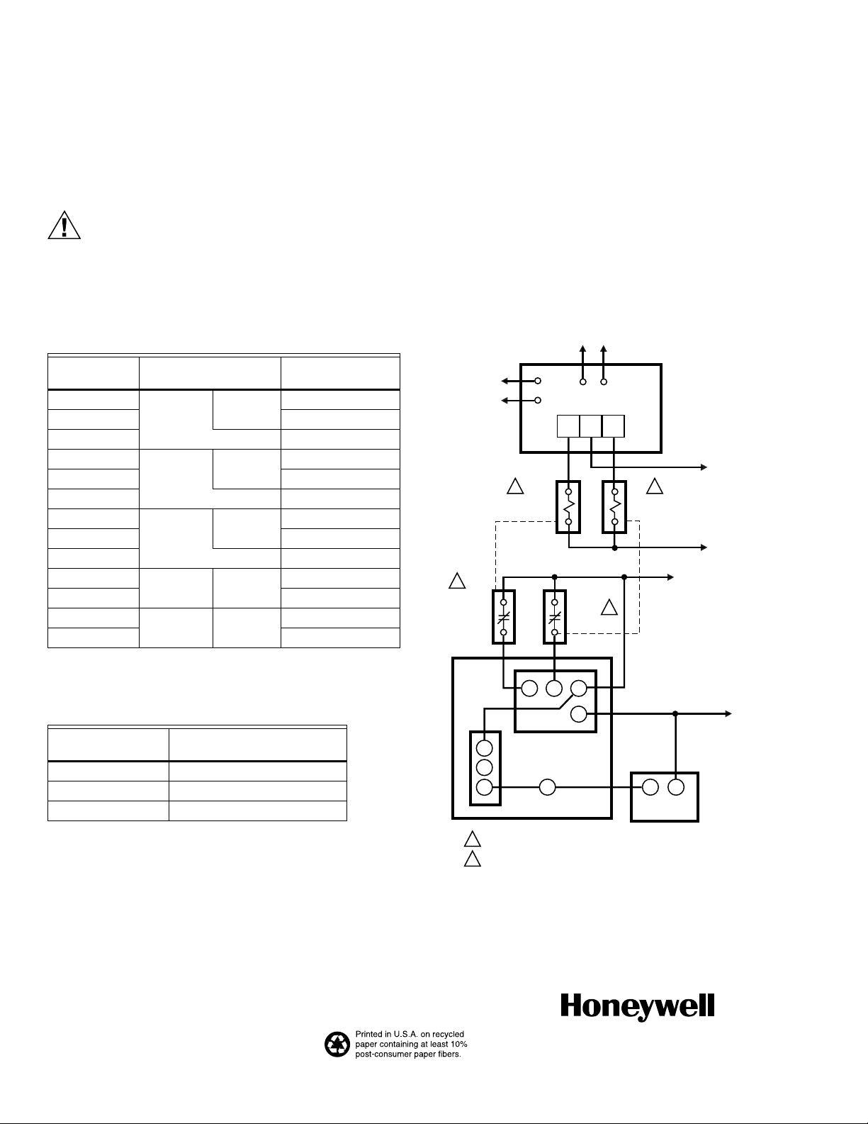
V4062A1156 Fluid Power Gas Actuator
The V4062A1156 Fluid Power Gas Valve Actuator was
modified to provide modulation between high-and low-fire
positions when used with a Series 60 controller, such as the
W964 Aquatrol™ System and two auxiliary relays.
The V4062A1156 will not operate properly wired similarly to
other V4062 models. See Fig. 7 for suggested wiring
procedure.
Ratings:
Voltage: 120V, 60 Hz.
Nominal Opening Time: 26 seconds.
Closing Time: one second maximum.
See Specifications section for further specifications.
OUTDOOR
SENSOR
W964
INDOOR
SENSOR
CBA
L1
1
R1
RELAY
CONTACT
1 2
R1
RELAY
COIL
R2
RELAY
CONTACT
V4062
3 4 1
R2
RELAY
COIL
L2
TO MAIN VALVE
TEMINAL ON
2
PROGRAMMER
Table 9. Gas Valve Replacement Seals.
Replacement Seal
Assy # Valve Size (in in.)
133393A 3/4, 1, 1-1/4, 1-1/2
133392A 2, 2-1/2, 3
137253A 4
Checkout
After the installation is complete, cycle the valve several times
with the manual fuel shutoff cock closed before testing the
system in actual operation.
Automation and Control Solutions
Honeywell International Inc. Honeywell Limited-Honeywell Limitée
1985 Douglas Drive North 35 Dynamic Drive
Golden Valley, MN 55422 Toronto, Ontario M1V 4Z9
customer.honeywell.com
® U.S. Registered Trademark
© 2007 Honeywell International Inc.
60-2099—10 M.S. Rev. 06-07
2
C
AUX.
NC
SWITCH
NO
1
R1 – NORMALLY CLOSED RELAY CONTACT.
2
R2 – NORMALLY OPEN RELAY CONTACT.
5
Fig. 7. Suggested wiring diagram.
L2
V4055
1 2
M7341
 Loading...