

Page 1
Design
V4044C and V4044F zone valves consist of:
• 3-way valve housing with BSPP internal threads
• Control ball assembly
• Actuator assembly with cable
• V4044F1000 with SPDT end switch
• V4044F1034 with SPST end switch
Materials
• Valve housing made of forged brass
• Spindle shaft made of brass
• O-ring seals made of EPDM rubber
• Ball plug made of NBR rubber
• Actuator cover and base made of zinc-plated steel
V4044C, V4044F
Motorized Zone Valves
3-PORT HYDRONIC VALVES
PRODUCT DATA
Application
Honeywell V4044C and F 3-port hydronic valves are used in
domestic and small commercial heating and cooling
applications to control the flow of hot or cold water.
They are designed for on-off zone control of domestic systems and can be used to control individual fan coil, radiator,
space heater or convector applications. They can be controlled by a line voltage SPST controller such as a room
thermostat, aquastat or flow switch.
The actuator head is removable without affecting the integrity
of the water system.
Features
• Rugged design
• Control by a line voltage SPST controller
• Actuator head installation does not require draining of
the system
• High flow rate capacity
• Indifferent to dirt in system
Specifications
Medium Water or water-glycol mixture
pH-value 8...9.5
Operating temperature 5...88°C (41...190°F)
Ambient temperature max. 50°C (122°F)
Operating pressure max. 8.6 bar (125 psi) static
Differential pressure see chapter “Dimensions” below
k
vs (cv)-values see chapter “Dimensions” below
Flow AB →A or B
Starting position port A normally closed
Voltage 220-240V, 50Hz
Power consumption 6W / 0.042A
Auxiliary switch rating 2.2A at 230Vac, 50Hz
Nominal timing On: 30 seconds under power
Electrical termination 1m flying lead, heat resistant
Shipping temperature -40…65°C (-40…149°F)
Humidity rating 5…95% RH (non-condensing)
Atmosphere non-corrosive, non-explosive
(max. 50% glycol content),
quality to VDI 2035
Off: 12 seconds under spring
return
cable
Honeywell • All rights reserved EN0H-0325GE25 R0906
Page 2
V4044C, V4044F
Function
V4044C and V4044F 2-position hydronic valves are used in
domestic and small commercial applications to control the
flow of hot or cold water. They consist of an actuator and a
valve.
With the manual opener set to AUTO and the actuator
energized, port A of the valve is opened and port B is closed.
When the actuator is de-energized, a spring-return
mechanism drives the ball to close port A, opening port B.
Port A can also be opened with no electrical power by moving
the manual opening lever over the stop and pushing slowly
and firmly to the MAN. OPEN position. The stop permits the
valve to be locked with port A in the open position. The valve
returns to the automatic position when the valve is energized.
A power failure will leave the valve at the spring-returned
position. When power is restored, the valve will respond to
controller demand.
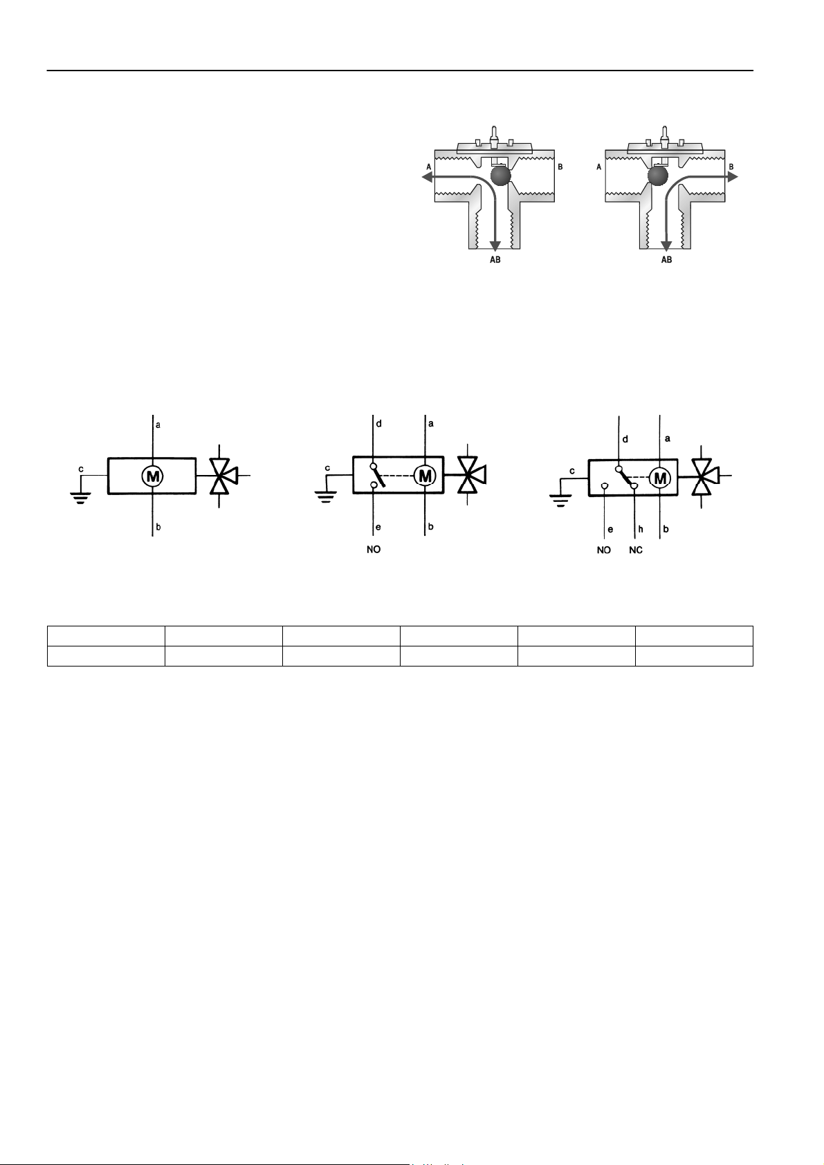
Wiring
Fig. 1. V4044C/F in
energized position (AB-A)
NOTE: Port AB is always open
Fig. 2. V4044C/F in de-
energized position (AB-B)
Fig. 3. Wiring diagram for V4044C Fig. 4. Wiring diagram for
V4044F1034
Table 1. Cable colour coding
a b c d e h
brown blue green/yellow orange grey white
NOTE: The V4044C has no end switch. It is equipped with a 3 wire cable (line, neutral, earth)
The V4044F1034 has an SPST end switch. It is equipped with a 5-wire cable (line, neutral, earth, end switch). The end
switch closes when the valve is in position AB – B
The V4044F1000 has an SPDT end switch. It is equipped with a 6-wire cable (line, neutral, earth, end switch NO, end
switch NC)
The length of all cables is 1m
Fig. 5. Wiring diagram for
V4044F1000
EN0H-0325GE25 R0906 2 Honeywell • All rights reserved
Page 3

V4044C, V4044F
Dimensions
Fig. 6. V4044C, V4044F 3-way zone valve
Table 2. Main dimensions and other values
Dimensions Body kvs-value max. close-
off pressure
R L C H
1/2” BSPP (internal) 3.0 1.4 bar 1/2” 96 46 128
3/4” BSPP (internal) 6.0 0.7 bar 3/4” 96 46 128
1” BSPP (internal) 8.1 0.55 bar 1” 96 46 128
3/4” BSPP (internal) 6.0 0.7 bar 3/4” 96 46 128
1” BSPP (internal) 8.1 0.55 bar 1” 96 46 128
NOTE: All dimensions in mm if not otherwise stated
Ordering Information
Table 3. Order information and OS-Nos. (OS=Ordering System)
Order text Size End switch Packing unit OS-No.
V4044C motorized zone valve
1/2” — 1 pc V4044C1452
3/4” — 1 pc V4044C1460
1” — 1 pc V4044C1478
V4044F motorized zone valve with end
switch
V4044F motorized zone valve with end
switch – bulk pack of 10
3/4” SPST 1 pc V4044F1000
1” SPDT 1 pc V4044F1034
3/4” SPST 10 pcs V4044F1000B
1” SPDT 10 pcs V4044F1034B
NOTE: Valves in bulk packs are not packed individually. Only one installation and operating instruction is supplied with the
bulk pack.
Honeywell • All rights reserved 3 EN0H-0325GE25 R0906
Page 4

V4044C, V4044F
ACS Control Products
Honeywell GmbH
Hardhofweg
74821 Mosbach, Germany
Phone: +49 (6261) 810
Fax: +49 (6261) 81393
www.honeywell.com
EN0H-0325GE25 R0906
September 2006
© 2006 Honeywell International Inc.
Subject to change • All rights reserved
Manufactured for and on behalf of the Environmental and Combustion
Controls Division of Honeywell Technologies Sàrl, Ecublens,
Route du Bois 37, Switzerland or by its Authorized Representative.
 Loading...