

Page 1
V4043A,B,E,J; V4044A,B; V8043A,B,E,F,J;
60-2133-9
V8044A,B,E Motorized Valves
PRODUCT DATA
FEATURES
• The V4043 and V8043 provide 2-position, straightthrough control of water.
• The V4044 and V8044 provide 2-position diverting
control of water.
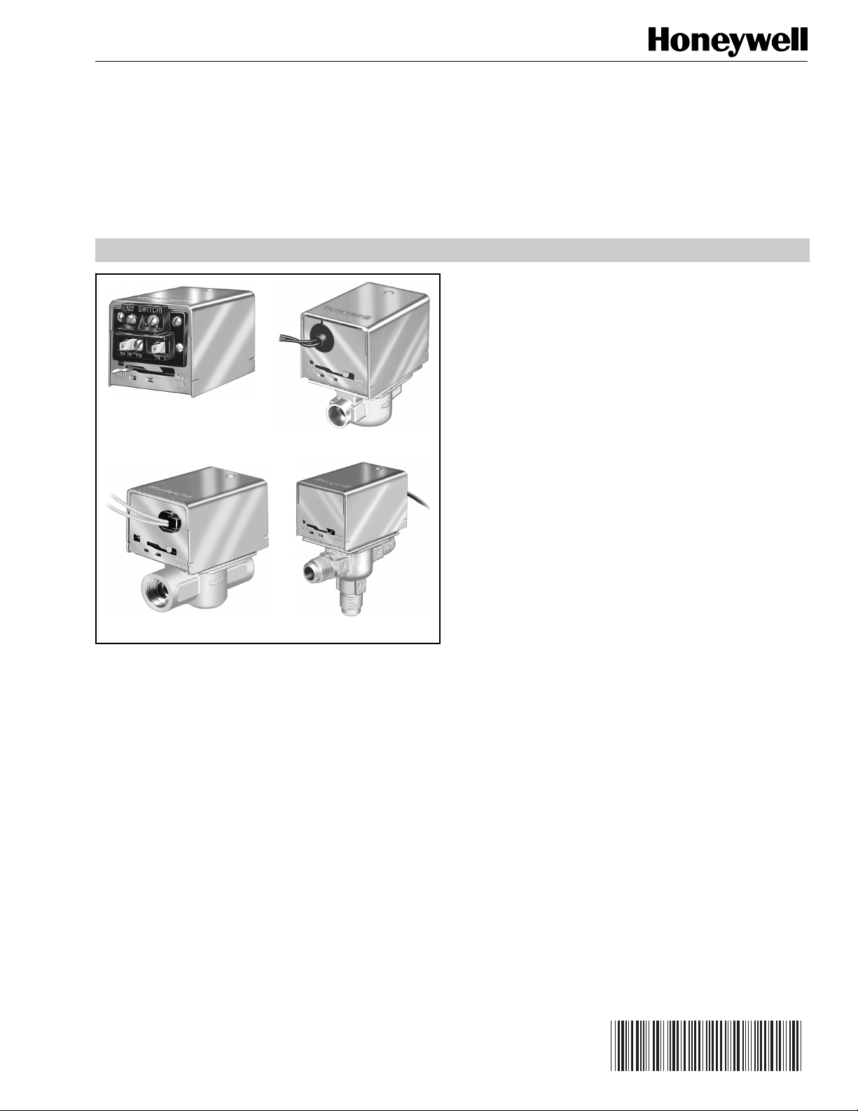
V4043, V4044, V8043, V8044
Replacement Powerhead
V4043, V8043
V8043 Inverted Flare V4044, V8044
APPLICATION
These valves consist of an actuator motor and valve
assembly for controlling the flow of hot or cold water, or
steam.
IMPORTANT
These valves are not for use in systems containing
dissolved oxygen.
• Compact construction for easy installation.
• Manual opener for valve operation on power failure.
Valve returns to automatic position when power is
restored.
• Choice of sweat or flare fitting brass end connections
for standard copper tubing.
• Motor can be replaced by removing one screw,
without disturbing the valve body or draining the
system.
• Complete powerhead may be removed or replaced
without breaking the line connections or draining the
system.
• All models can be installed without disassembling
the valve.
• Fits under the cover of most baseboards.
•Available with integral auxiliary end switch (V4044B;
V8043E,F; V8044E) to permit sequencing of auxiliary
equipment.
• V4043E and V8043J provide straight-through control
of steam.
® U.S. Registered Trademark
Copyright © 1996 Honeywell Inc. • All Rights Reserved
Contents
Application........................................................................... 1
Features .............................................................................. 1
Specifications ...................................................................... 2
Ordering Information ........................................................... 2
Installation ........................................................................... 10
Operation and Checkout ..................................................... 20
Page 2

V4043A,B,E,J; V4044A,B; V8043A,B,E,F,J; V8044A,B,E MOTORIZED VALVES
SPECIFICATIONS
TRADELINE® Models
TRADELINE® models are selected and packaged to provide
ease of stocking, ease of handling, and maximum
replacement value. TRADELINE® model specifications are
the same as those of standard models except as noted
below.
TRADELINE® Models Available:
V8043A,E, and V8043E,F (see Table 1).
Capacity Rating:
3.5 Cv (3.0 kV) nominal. (See Electrical Ratings table in
Standard Models section and Table 1.)
Additional Feature:
End switch enclosure included.
Standard Models
Models:
V4043: line voltage, straight-through valves.
V4044: line voltage, 2-position diverting valves.
V8043: low voltage, straight-through valves.
V8044: low voltage, 2-position diverting valves.
See Table 1.
Electrical Ratings
(See Table 1 for Voltage of Specific Models):
Voltage Amperes Voltage Amperes
24 0.320
100 0.087 240 0.040
120 0.080 277 0.037
208 0.044 — —
a
Maximum five V8043 Zone Valves per 40 VA transformer.
Changeover Aquastat® Control:
120V, 3.0A with 10.0A inrush.
End Switch:
120V, 4.4A running with 26.4A inrush (60 Hz). Pilot duty 50
VA at 24V.
Timing:
V4043 and V8043: Open or close in 15 seconds
maximum.
V4044 and V8044: Divert flow in 30 seconds maximum.
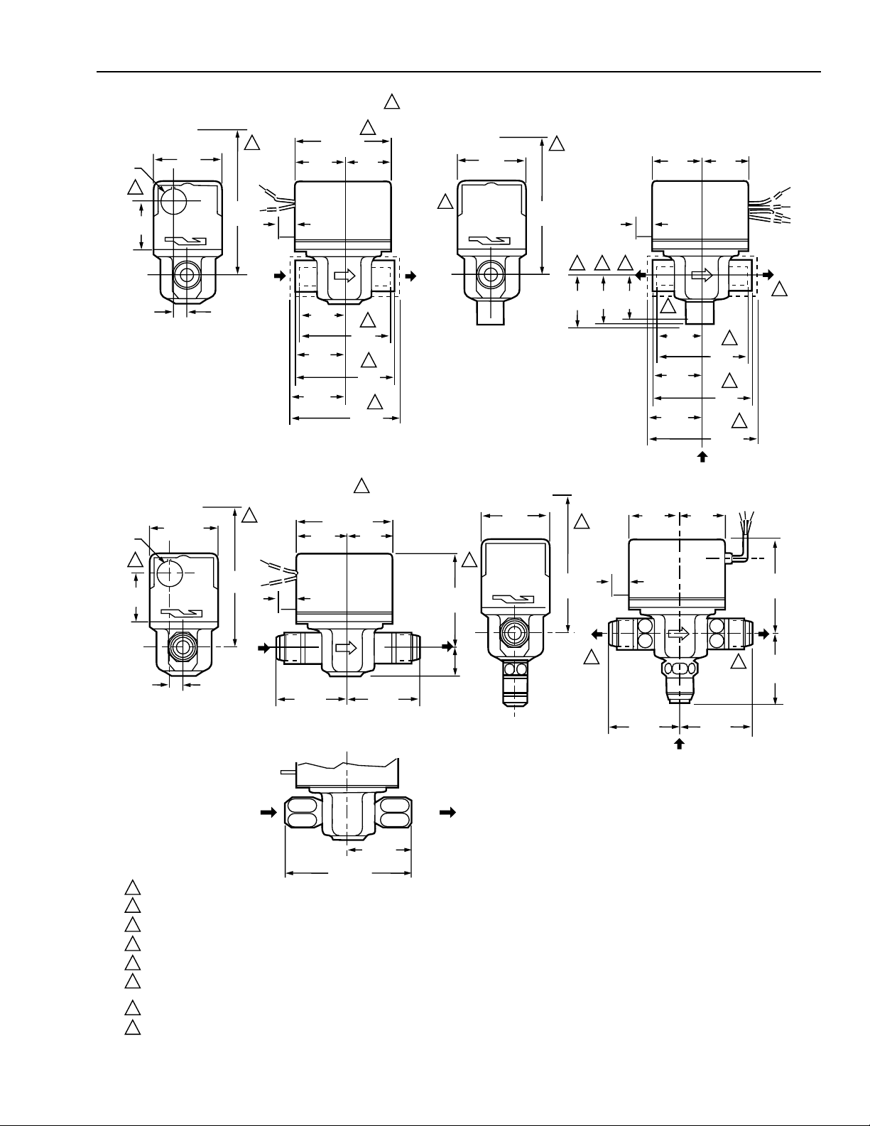
Dimensions:
See Fig. 1.
Manual Opener:
Manual opener (on all except the straight-through, normally
open valves) allows opening the valve in case of power
failure. Valve returns to automatic position when power is
restored.
a
220 0.042
ORDERING INFORMATION
For ordering information when purchasing replacement and modernization products from your TRADELINE® wholesaler or
your distributor, refer to the TRADELINE® Catalog or price sheets for complete ordering number, or specify:
1. Order number.
2. Voltage and frequency.
3. Size and type of end connections.
4. Cv (kV) rating.
5. Lead length if different from standard.
6. Replacement parts, if needed.
If you have additional questions, need further information, or want to comment on our products or services, please write or
phone:
1. Your local Honeywell Home and Building Control sales office (check white pages of phone directory).
2. Home and Building Control Customer Relations
Honeywell, 1885 Douglas Drive North
Minneapolis, Minnesota 55422-4386
In Canada—Honeywell Limited/Honeywell Limitee, 35 Dynamic Drive, Scarborough, Ontario M1V 4Z9. International Sales
and Service Offices in all principal cities of the world. Manufacturing in Australia, Canada, Finland, France, Germany, Japan,
Mexico, Netherlands, Spain, Taiwan, United Kingdom, U.S.A.
60-2133—9
2
Page 3
V4043A,B,E,J; V4044A,B; V8043A,B,E,F,J; V8044A,B,E MOTORIZED VALVES
7/8 DIA.
(22)
8
1-1/2
(38)
15/32
(12)
7/8 DIA.
(22)
7
1-1/2
(38)
15/32
(12)
V043, V8043 SWEAT COPPER CONNECTION MODELS
3-1/2 (89)
1-3/4
(44)
AB
1-9/16
(40)
1-3/4
(44)
1-7/8
(47)
AUTO
2-3/8
(60)
MAN OPEN
5-1/4
(133)
1
3/8
(10)
IN
V4043, V8043 FLARE-FITTING MODELS
2-3/8 (60)
AUTO
MAN OPEN
5-1/4
(133)
1
IN
3/8
(10)
A
2-11/32
(59)
1-3/4
(44)
3-1/2 (89)
V8043 INVERTED FLARE MODELS
5
1-3/4
(44)
2
3-1/8
(79)
3
3-1/2
(89)
3-11/16
(94)
6
1-3/4
(44)
2-11/32
6
V4044, V8044 SWEAT COPPER CONNECTION MODELS
1
2-3/8
(60)
OUT
8
MAN OPEN
AUTO
5-1/4
(133)
4 3 2
1-11/16
1-7/8
(43)
(48)
3/8
(10)
1-1/2
(38)
4
1-3/4
(44)
AB
1-3/4
(44)
7
7
AB
1-9/16
(40)
1-3/4
(44)
1-7/8
(47)
3-1/8
(79)
3-1/2
(89)
3-11/16
(94)
2
3
4
INLET
V4044, V8044 FLARE-FITTING MODELS
2-3/8
(60)
1
1-3/4
(44)
1-3/4
(44)
8
5-1/4
3/8
MAN OPEN
AUTO
3-1/8
(79)
OUT
B
(133)
(10)
A
7
7/8
(22)
AB
3-1/8
(79)
B
2-1/4
7
(57)
(59)
2-11/32
(59)
2-11/32
(59)
INLET
IN
1-13/16
(46)
OUT
3-5/8 (92)
HEIGHT NEEDED TO REMOVE COVER.
1
2
DIMENSIONS FOR 1/2 IN. COPPER TUBING.
3
DIMENSIONS FOR 3/4 IN COPPER TUBING.
DIMENSIONS FOR 1 IN. COPPER TUBING.
4
4-7/8 IN. (124) MAX ON V8034F WITH TERMINAL BOARD ENCLOSURE.
5
V4034B AND V8043B VALVES THAT ARE NORMALLY OPEN IN THE DE-ENERGIZED POSITION HAVE NO MANUAL LEVER. THE VALVES ALSO HAVE A REVERSED
6
POWERHEAD WHERE THE LEADWIRES EXIT THE POWERHEAD ABOVE THE B (OUTLET) PORT RATHER THAN ABOVE THE A (INLET) PORT.
7
REFER TO MOUNTING INSTRUCTIONS.
8
OPENING FOR 1/2 IN. CONDUIT ON MANUAL LEVER SIDE FOR V4043, V8043; OPENING ON OPPOSITE SIDE FOR V4044, V8044.
Fig. 1. Mounting dimensions in in. (mm) of V4043/44, V8043/44 Motorized Valves.
3
M10175
60-2133—9
Page 4
V4043A,B,E,J; V4044A,B; V8043A,B,E,F,J; V8044A,B,E MOTORIZED VALVES
Table 1. Powerhead and Valve Body Specifications
Flow Capacity
Rating
Control
Model
V4043A 120V, 60 Hz 1.0 .86
Circuit Cv kV Wire Hookup Type
18 in. (457 mm) leadwires,
120V, 60 Hz 3.5 3.0
1/2 in. conduit opening.
120V, 60 Hz 8.0 7.0 Sweat 3/4
120V, 60 Hz 8.0 7.0 Sweat 1
120V, 60 Hz 3.5 3.0 NPT 1/2
120V, 60 Hz 3.5 3.0 NPT 3/4
120V, 60 Hz 10.0 8.6 NPT 1
208V, 60 Hz 3.5 3.0 Flare 1/2
220V, 50 Hz 3.5 3.0 Flare 1/2
240V, 50 or
3.5 3.0 Sweat or
60 Hz
V4043B 120V, 60 Hz 1.0 .86
120V, 60 Hz 3.5 3.0
18 in. (457 mm) leadwires,
1/2 in. conduit opening.
240V, 60 Hz 3.5 3.0 Sweat 1/2
V4043E
(steam only)
120V, 60 HzaCv not
applicable
18 in. (457 mm) leadwires,
1/2 in. conduit opening.
(15 psi
[103 kPA] low
pressure
steam rating).
208V, 60 Hz Sweat 1/2
240V, 60 Hz Sweat 1/2
V4044A 120V, 60 Hz 4.0 3.4 18 in. (457 mm) leadwires,
1/2 in. conduit opening.
120V, 60 Hz 7.0 6.0 Sweat
120V, 60 Hz 4.0 3.4 Sweat
208V, 60 Hz 4.0 3.4 Sweat 1/2
220V, 50 Hz 4.0 3.4 Sweat or
220V, 50 Hz 7.0 6.0 Sweat 3/4
240V, 50 Hz 4.0 3.4 Sweat or
240V, 60 Hz 4.0 3.4 Sweat or
277V, 60 Hz 4.0 3.4 24 in. (610 mm) leadwires,
1/2 in. conduit opening.
V4044B
(bottom inlet)
b,c
120V, 60 Hz 4.0 3.4 18 in. (457 mm) leadwires,
1/2 in. conduit opening.
120V, 60 Hz 7.0 6.0 Sweat 3/4
220V, 50 Hz 4.0 3.4 Flare 1/2
Pipe
Connections
Size
(in.)
Sweat 1/2
Sweat or
1/2
Flare
1/2
Flare
Sweat 1/2
Sweat or
1/2
Flare
d
Sweat
Sweat or
Flare
1/2 Straight-
1/2 2-position
c
c
3/4
e
1/2
1/2
Flare
1/2
Flare
1/2
Flare
Sweat 1/2
Sweat or
1/2 2-position
Flare
Valve
Body
De-energized
Position
Straight- Normally
through Closed
Straight-
Normally Open
through
Normally
through
Closed
Port A Normally
diverting
Closed
Port A Normally
diverting
Closed
60-2133—9
4
Page 5
V4043A,B,E,J; V4044A,B; V8043A,B,E,F,J; V8044A,B,E MOTORIZED VALVES
Flow Capacity
Rating
Control
Model
Circuit Cv kV Wire Hookup Type
V8043A 24V, 60 Hz 3.5 3.0 18 in. (457 mm) leadwires,
1/2 in. conduit opening.
24V, 60 Hz 3.5 3.0 NPT 1/2
24V, 60 Hz 3.5 3.0 Sweat 3/4
24V, 60 Hz 8.0 7.0 36 in. (914 mm) leadwires,
1/2 in. conduit opening.
24V, 60 Hz 3.5 3.0 18 in. (457 mm) leadwires,
1/2 in. conduit opening.
V8043B 24V, 60 Hz 3.5 3.0 18 in. (457 mm) leadwires,
1/2 in. conduit opening.
24V, 60 Hz 3.5 3.0 Sweat 3/4
24V, 60 Hz 3.5 3.0 NPT 3/4
V8043E 24V, 60 Hz 3.5 3.0 18 in. (457 mm) leadwires
and end switch, 1/2 in.
conduit opening.
24V, 60 Hz 3.5 3.0 Sweat 3/4
24V, 60 Hz 3.5 3.0 Sweat 1
24V, 60 Hz 8.0 7.0 Sweat 3/4
24V, 60 Hz 8.0 7.0 Sweat 1
24V, 60 Hz 10.0 8.6 NPT 1
24V, 60 Hz 3.5 3.0 NPT 3/4
V8043F 24V, 60 Hz 3.5 3.0 Terminal Board and end
switch.
24V, 60 Hz 3.5 3.0 Sweat 3/4
24V, 60 Hz 3.5 3.0 Sweat 1
24V, 60 Hz 8.0 7.0 Sweat 3/4
24V, 60 Hz 8.0 7.0 Sweat 1
V8043J 24V, 60 Hz
d
Cv not
applicable. (15
18 in. (457 mm) leadwires,
1/2 in. conduit opening.
psi [103 kPa]
low pressure
steam rating).
24V, 60 Hz NPT 1/2
24V, 60 Hz NPT 3/4
V8044A 24V, 60 Hz 4.0 3.4 18 in. (457 mm) leadwires,
1/2 in. conduit opening.
24V, 60 Hz 7.0 6.0 Sweat 3/4
24V, 60 Hz 4.0 3.4 50 in. (1270 mm)
stranded leadwires, 1/2
conduit opening.
24V, 60 Hz 4.0 3.4 18 in. (457 mm) leadwires,
1/2 in. conduit opening.
24V, 60 Hz 4.0 3.4 NPT 3/4
Pipe
Connections
Sweat or
Flare
Size
(in.)
1/2 Straight-
Valve
Body
through
Sweat 3/4
Sweat 1
Sweat 1/2 Straight-
through
Sweat 1/2 Straight-
through
Sweat 1/2 Straight-
through
d
Sweat 1/2 Straight-
through
Sweat or
Flare
1/2 2-position
e
diverting
Sweat 1/2
NPT 1/2
De-energized
Position
Normally
Closed
Normally Open
Normally
Closed
Normally
Closed
Normally Open
Port A Normally
Closed
5
60-2133—9
Page 6
V4043A,B,E,J; V4044A,B; V8043A,B,E,F,J; V8044A,B,E MOTORIZED VALVES
Flow Capacity
Rating
Control
Model
V8044B 24V, 60 Hz
Circuit Cv kV Wire Hookup Type
b
4.0 3.4 18 in. (457 mm) leadwires,
Sweat 1/2 2-position
1/2 in. conduit opening.
V8044E 24V, 60 Hz 4.0 3.4 18 in. (457 mm) leadwires
Sweat 1/2 2-position
and end switch, 1/2 in.
conduit opening.
24V, 60 Hz 7.0 6.0 Sweat 3/4
a
30 in. (762 mm) leads also available.
b
Includes integral changeover Aquastat® Control.
c
96 in. (2438 mm) leads also available.
d
30 in. (762 mm) leads also available.
e
Valve available with reduced (2.5 Cv [2.1 kV] ) rating on bypass port. Sweat fitting only.
Approvals:
Underwriters Laboratories Inc. Listed: V4043A,B,E;
V4044A,B; V8043A,B,E,J; V8044A,B,E: File MH11826, Vol.
1, dated 2-22-88.
Conversion Kits:
Conversion kits for converting old style (series 1-5) valve
bodies to accept 40003916 Powerhead (use with V4043,
V4044, V8043, V8044). Includes metal plate with driveshaft
and rubber ball, O-Ring and four screws.
Replacement Parts:
Motor Part Numbers (use with V4043, V4044, V8043,
V8044):
Tw o-way water valve body: 40003918-006.
Three-way water valve body: 40003918-007.
Tw o-way steam valve body: 40003918-008.
802360JA 24 Vac, 60 Hz, Class A, plated.
802360LA 120 Vac, 60 Hz, Class F, plated.
802360MA 208 Vac, 60 Hz, Class F, plated.
802360NA 220V 50 Hz, 240V 60 Hz, Class F, plated.
802360UA 24 Vac, 60 Hz, Class F, plated.
O-Ring Part Numbers:
272742A—Includes replacement ball plug, large O-Ring
and four screws.
272756A—Package of five large O-Rings.
Pipe
Connections
Size
(in.)
Valve
Body
diverting
diverting
De-energized
Position
Port A Normally
Closed
Port A Normally
Closed
Powerhead (see Table 2):
Includes motor, housing and two mounting screws.
Accessories:
803867A Conduit Cover: Includes 803858 Cover and
803859 Case (for V8043F).
Flow and Temperature Ratings:
Flow Capacity
Rating
Valve Family Cv kV psi kPa
Maximum
Closeoff Pressure
Max Fluid Min Fluid Max Ambient
Temperature Temperature Temperature
V4043A,B,E,J 1.0 .86 50 345 240°F (116°C) 40°F (5°C) 125°F (50°C)
3.5 3.0 20 138 240°F (116°C) 40°F (5°C) 125°F (50°C)
10.0 8.6 6.5 45 240°F (116°C) 40°F (5°C) 125°F (50°C)
V8043A,B,E,F 3.5 3.0 20 138 200°F (93°C) 40°F (5°C) 125°F (50°C)
8.0 7.0 8 55 200°F (93°C) 40°F (5°C) 125°F (50°C)
10.0 8.6 6.5 45 200°F (93°C) 40°F (5°C) 125°F (50°C)
V4044A,B 4.0 3.4 20 138 240°F (116°C) 40°F (5°C) 125°F (50°C)
7.0 6.0 10 69 240°F (116°C) 40°F (5°C) 125°F (50°C)
V8044A,B,E 4.0 3.4 20 138 200°F (93°C) 40°F (5°C) 125°F (50°C)
7.0 6.0 10 69 200°F (93°C) 40°F (5°C) 125°F (50°C)
V4043E, V8043J (steam) — — 15
a
103 240°F (116°C) 40°F (5°C) 125°F (50°C)
Static Pressure Rating of 125 psi (862 kPa) applies to all valves.
a
15 psi low pressure steam.
60-2133—9
6
Page 7

V4043A,B,E,J; V4044A,B; V8043A,B,E,F,J; V8044A,B,E MOTORIZED VALVES
Table 2. Replacement Powerheads.
Valve
Model
Number Part Number
V4043A 40003916-022 Same 220/50, 240/60 0.04 18 in (457 mm) leads
40003916-023 Same 240, 50 0.04
40003916-024 Same 120, 60 0.08
V4043B 40003916-030 Same 240, 60 0.04
40003916-031 Same 120, 60 0.08
40003916-042 Same 208, 60 0.04
V8043A 40003916-021 Same 24, 50/60 0.32 Class A
V8043B 40003916-027 Same 24, 50/60 0.32
V8043E 40003916-026 Same 24, 50/60 0.32
V8043F 40003916-048 Same 24, 50/60 0.32 Terminal Board
V4044A 40003916-034 Opposite 240, 50 0.04 18 in. (457 mm) leads
40003916-035 Opposite 220/50, 240/60 0.04
40003916-036 Opposite 120, 60 0.08 96 in. (2438 mm) leads
40003916-047 Same 120, 60 0.08
V4044B 40003916-039 Opposite 220/50, 240/60 0.04 18 in. (457 mm) leads
40003916-040 Opposite 120, 60 0.08
40003916-045 Same 120, 60 0.08
V8044A 40003916-032 Opposite 24, 50/60 0.32 18 in. (457 mm) leads
40003916-046 Same 24, 50/60 0.32
V8044B 40003916-037 Opposite 24, 50/60 0.32 18 in. (457 mm) leads
40003916-044 Same 24, 50/60 0.32
Electrical Connection
on Which Side of
Manual Lever
Voltage (Vac)
and Frequency
(Hz)
Current
Draw (A)
Type of Electrical
Connection Motor
(conduit opening)
(conduit opening)
(conduit opening)
(conduit opening)
(conduit opening)
(conduit opening)
Class F;
plated
Class F;
plated
Class A;
plated
How to Find Maximum Valve Operating
Temperature
The maximum operating temperature for motorized valves
depends on the maximum ambient temperature at the valve
location, and on the maximum fluid temperature. Using the
graph in Fig. 2, find the maximum valve operating
temperature as follows:
쐃 Measure the ambient temperature at the valve and
locate that temperature on the ambient temperature
scale on the graph.
쐇 Draw a line from the ambient temperature, parallel with
the fluid temperature scale, to the maximum fluid
temperature line.
쐋 Draw a line from that point down to the fluid
temperature scale to find the maximum operating
temperature. (Note the example shown by the dashed
line in Fig. 2.)
To find the maximum ambient temperature for a valve when
the fluid temperature is known, reverse the procedure.
7
60-2133—9
Page 8

V4043A,B,E,J; V4044A,B; V8043A,B,E,F,J; V8044A,B,E MOTORIZED VALVES
210
(99)
200
(93)
190
(88)
180
(82)
170
(77)
160
(71)
150
(66)
140
(60)
AMBIENT TEMPERATURE
130
(54)
120
(49)
110
(43)
100
(38)
90
(32)
80
(27)
MAXIMUM AMBIENT
TEMPERATURE LINE
EXAMPLE: 150°F (66°C) IS THE AMBIENT TEMPERATURE AT THE VALVE,
235°F (113°C) IS MAXIMUM FLUID TEMPERATURE.
MAXIMUM FLUID
TEMPERATURE
LINE
90
(32)
100
(38)
110
(43)
120
(49)
130
(54)
FLUID TEMPERATURE
DEGREES F
DEGREES C
70
(21)
80
(27)
Fig. 2. Maximum temperature characteristics of valves with Class F motors.
How to Find Valve Pressure Drop
The pressure drop in psi (kPa), equivalent ft (m) of pipe, or
feet of water (kPa) can be calculated from Fig. 3 through 8
as follows:
쐃 Calculate the flow rate to heat the zone.
쐇 Determine the Cv (kV) rating of the motorized valve.
쐋 Select the graph corresponding to the Cv (kV) rating
(Fig. 3 through 8).
쐏 Determine the pressure drop across the valve using
the following procedures for calculating pressure drop.
Pressure Drop in psi (kPa)
쐃 Locate the flow rate at the bottom of the graph.
쐇 Draw a line up from the flow rate to the intersection of
the curve.
쐋 Draw a line from the intersection to the left edge of the
graph to determine the pressure drop in psi (kPa).
140
(60)
150
160
170
180
190
200
210
220
230
240
(66)
(71)
(77)
(82)
(88)
(93)
(99)
(104)
(110)
(116)
Pressure Drop in Equivalent ft (m) of Pipe
NOTE: Both 1/2 and 3/4 in. pipe conversion scales are
available for this determination.
쐃 Locate the flow rate at the bottom of the graph.
쐇 Draw a line vertically to the top of the graph.
Determine the pressure drop for either the 1/2 or 3/4
in. pipe.
Pressure Drop in ft of Water (kPa)
쐃 Locate the flow rate at the bottom of the graph.
쐇 Draw a line up from the flow rate to the intersection of
the curve.
쐋 Draw a line from the intersection to the right edge of
the graph to determine pressure drop in ft of water
(kPa).
250
(121)
M8164
60-2133—9
8
Page 9

V4043A,B,E,J; V4044A,B; V8043A,B,E,F,J; V8044A,B,E MOTORIZED VALVES
PRESSURE DROP, EQUIVALENT FEET OF PIPE (EQUIVALENT METERS OF PIPE)
120
100
90
(37)
(30)
(27)
30 (207)
20 (138)
10 (69)
9 (62)
8 (55)
7 (48)
6 (41)
5 (34)
4 (28)
3 (21)
PRESSURE DROP psi (kPa)
2 (14)
1 (7)
0
2
(0.13)
140
(43)
1CV
(0.86 KV)
6
4
(0.38)8(0.5)
(0.25)
GAL/MIN (l/s) FLOW RATE
500
600
(152)
(183)
10
(0.63)12(0.76)
(3/4 IN. PIPE)(1/2 IN. PIPE)
700
(213)
750
(229 )
-50 (149)
-40 (119)
-30 (89.5)
-20 (60)
-10 (30)
-5 (15)
Fig. 3. Flow characteristics of 1 Cv (0.86 kV) flow.
PRESSURE DROP, EQUIVALENT FEET OF PIPE (EQUIVALENT METERS OF PIPE)
(3/4 IN. PIPE)
9.0
(2.7)
10
8.0
(3)
(2.4)
50.0 (345)
10.0 (69)
5.0 (34)
1.0 (7)
0.50 (3.4)
PRESSURE DROP psi (kPa)
0.10 (0.69)
FT OF WATER psi (kPa) PRESSURE DROP
0.05 (0.34)
0
M9183A
0
(0.13)4(0.25)
Fig. 5. Flow characteristics of 3.5 Cv (3.0 kV) valve.
45
(13.7)
(18)
12
11
(3.6)
(3.4)
2
GAL/MIN (l/s) FLOW RATE
60
12.5
(3.8)
(0.38)
65
(20)
13
(4)
3.5CV
(3.0 KV)
8
6
(0.5)10(0.63)12(0.76)
70
(21.3)
(1/2 IN. PIPE)
14
(0.88)
(24.4)
-50 (149)
-40 (119)
-30 (89.5)
-20 (60)
-10 (30)
-5 (15)
-1 (3)
-0.5 (1.5)
-0.1 (0.3)
-0.05 (0.15)
M5979B
80
PRESSURE DROP FT OF WATER psi (kPa)
PRESSURE DROP, EQUIVALENT FEET OF PIPE (EQUIVALENT METERS OF PIPE)
45
8
(2.4)9(2.7)10(3)
0
(0.13)
(13.7)60(18)
2
(3/4 IN. PIPE)
50.0 (345)
10.0 (69)
5.0 (34)
1.0 (7)
.50 (3.4)
PRESSURE DROP psi (kPa)
.10 (0.69)
.05 (0.34)
11
(3.4)12(3.6)
12.5
(3.8)
2.5CV
4
6
(0.25)
(0.38)8(0.5)
GAL/MIN (l/s) FLOW RATE
65
(20)
(2.1 KV)
70
(21.3)
13
(4)
(1/2 IN. PIPE)
10
(0.63)12(0.76)14(0.88)
80
(24.4)
-50 (149)
-40 (119)
-30 (89.5)
-20 (60)
-10 (30)
-5 (15)
-1 (3)
-0.5 (1.5)
-0.1 (0.3)
-0.05 (0.15)
M9184A
Fig. 4. Flow characteristics of V4043A model with 2.5 C
(2.1 kv) rating and V4044A and V8044A bypass port (B)
with 2.5 Cv (2.1 kv) (reduced) rating.
PRESSURE DROP
EQUIVALENT FEET OF PIPE (EQUIVALENT METERS OF PIPE)
6.0
(1.8)
50
7.0
8.0
(1.5)
(2.1)
(2.4)
50.0 (345)
10.0 (69)
5.0 (34)
1.0 (7)
0.50 (3.4)
PRESSURE DROP psi (kPa)
0.10 (0.69)
0.05 (0.34)
FT OF WATER psi (kPa) PRESSURE DROP
02
(0.13)
v
Fig. 6. Flow characteristics of 4 Cv (3.4 kV) valve.
9.0
(2.7)
4
(0.25)
6
(0.38)
10
(3)
(0.5)
30
(9.1)40(12.2)
8
10
12
(0.63)
(0.76)
GAL/MIN (l/s)
45
(13.7)
4CV
(3.4 KV)
14
16
(0.88)
(1.1)
(1.0)
FLOW RATE
50
(15.2)
18
(3/4 IN. PIPE)(1/2 IN. PIPE)
(1.3)
55
(16.8)
20
22
(1.4)
24
(1.5)
60
(18)
26
(1.6)
28
(1.8)
-50 (149)
-40 (119)
-30 (89.5)
-20 (60)
-10 (30)
-5 (15)
-1 (3)
-0.5 (1.5)
-0.1 (0.3)
-0.05 (0.15)
30
(1.9)
PRESSURE DROP FT OF WATER psi (kPa)
M5717B
9
60-2133—9
Page 10

V4043A,B,E,J; V4044A,B; V8043A,B,E,F,J; V8044A,B,E MOTORIZED VALVES
PRESSURE DROP, EQUIVALENT FEET OF PIPE (EQUIVALENT METERS OF PIPE)
13
(4)10(3)
50.0 (345)
10.0 (69)
5.0 (34)
1.0 (7)
0.50 (3.4)
PRESSURE DROP psi (kPa)
0.10 (0.69)
0.05 (0.34)
0
15
(4.6)
2.0
(0.6)
2
(0.13)
17
(5.2)
(0.25)
4
19
(5.8)
(0.38)
21
22
(6.4)
(6.7)23(7)
3.5
(1)
(1/2 IN. PIPE)
7CV
(6.0 KV)
14
10
12
(0.88)
(0.63)
(0.76)
GAL/MIN (l/s) FLOW RATE
3.0
(0.9)
6
20
(6)
8
(0.5)
16
(1.0)
(7.3)25(7.6)
18
20
(1.1)
(1.3)
24
22
(1.4)
24
(1.5)
26
(1.6)
(3/4 IN. PIPE)
28
(1.9)
(1.8)
Fig. 7. Flow characteristics of 7 Cv (6.0 kV) valve.
-50 (149)
-40 (119)
-30 (89.5)
-20 (60)
-10 (30)
-5 (15)
-1 (3)
-.5 (1.5)
-.1 (0.3)
-0.05 (0.15)
30
M9185A
INSTALLATION
When Installing this Product…
1. Read these instructions carefully. Failure to follow them
could damage the product or cause a hazardous
condition.
2. Check the ratings given in the instructions and on the
product to make sure the product is suitable for your
application.
3. Installer must be a trained, experienced service
technician.
4. After installation is complete, check out product
operation as provided in these instructions.
CAUTION
FT OF WATER psi (kPa)
1. Disconnect power supply before connecting
wiring to prevent electrical shock or equipment
damage.
2. Normally it is not necessary to remove the
powerhead from the valve body during
installation. If the valve must be disassembled,
be certain that it is reassembled with the water
flow in the direction of the arrow. Reversal of the
powerhead results in damage to the gear train.
3. On 24V systems, never jumper the valve coil
terminals even temporarily. This can burn out the
heat anticipator in the thermostat.
PRESSURE DROP, EQUIVALENT FEET OF PIPE (EQUIVALENT METERS OF PIPE)
10
8
(3)12(3.7)
(2.4)
7
(2.1)
(2.7)
50.0 (345)
10.0 (69)
5.0 (34)
1.0 (7)
0.50 (3.4)
PRESSURE DROP psi (kPa)
0.10 (0.69)
0.05 (0.34)
0.01
0
9
(3.4)
1.5
(0.5)
2
(0.13)
1
(0.25)
4
2.0
(0.6)
13
(4)
(0.38)
15
14
(4.6)16(4.9)
(4.3)
2.5
(0.8)
(1/2 IN. PIPE)
8CV
(6.9 KV)
14
10
6
12
8
(0.88)
(0.63)
(0.76)
(0.5)
GAL/MIN (l/s) FLOW RATE
16
(1.0)
17
(5.2)18(5.5)
18
20
(1.1)
(1.3)
22
(1.4)
24
(1.5)
26
(1.6)
19
(5.8)
(1.8)
28
Fig. 8. Flow characteristics of 8 Cv (6.9 kV) valve.
(3/4 IN. PIPE)
-50 (149)
-40 (119)
-30 (89.5)
-20 (60)
-10 (30)
-5 (15)
-1 (3)
-0.5 (1.5)
-0.1 (0.3)
-0.05 (0.15)
30
(1.9)
M9186A
IMPORTANT
Use this valve in hydronic heating systems that do
not contain dissolved oxygen in the system water.
The dissolved oxygen, which is found in systems
that have a frequent source of makeup water,
causes the rubber plug inside the valve to
deteriorate and eventually fail.
Mounting
The valve can be mounted in any position on a vertical line.
See Fig. 9. If the valve is mounted horizontally; the
powerhead must be even with or above the center line of the
piping. Make sure to leave enough room above the
powerhead to remove the cover for servicing.
FT OF WATER psi (kPa) PRESSURE DROP
HORIZONTIAL
PIPING
VERTICAL
PIPING
M10162
60-2133—9
Fig. 9. Mounting positions.
10
Page 11

V4043A,B,E,J; V4044A,B; V8043A,B,E,F,J; V8044A,B,E MOTORIZED VALVES
Mount the valve directly in the tube or pipe. Make sure that
the flow through the valve is in the direction indicated by the
arrow stamped on the valve body.
On diverting valves, the three fittings or ports are labeled on
the bottom of the valve body casting. See Fig. 1. Port AB is
the inlet port and is open at all times. Port A is closed when
the valve is de-energized; port B is open when the valve is
de-energized. Refer to the equipment manufacturer
instructions to determine which port (A or B) should be
connected to the coil bypass.
Flare Fitting Models
Use new, properly reamed pipe, free from chips. The valve
body is threaded for standard 5/8 in. OD copper, 45 degree
SAE flare fitting nuts. These nuts are not furnished with the
valve and must be obtained separately.
Sweat Copper Models
쐃 Use new, properly reamed pipe, free from dents or
corrosion.
쐇 Place the valve on the pipe. Set the manual opening
lever to MAN. OPEN position before applying heat.
This protects the plug inside the valve by removing it
from the seat.
쐋 Sweat the joints, keeping the outer surface free from
solder. DO NOT use silver solder because of the high
melting temperature required.
To Install Replacement Powerhead
System with Old Style Valve Bodies (Series 1-5)
To install a replacement powerhead in a system with an old
style body (series 1-5), the valve body must be converted to
accept the new powerhead using part no. 40003918
Conversion Kit. The kit includes a metal plate with a
driveshaft and rubber plug, O-ring, and four screws.
쐏 Remove the old powerhead from the valve body
(Fig. 10):
a. Place the manual opening lever (normally closed
models only) on the old powerhead in the MAN.
OPEN position (see Fig. 10A).
b. Remove the cover (Fig. 10B).
c. With the cover off, remove the four screws
securing the powerhead to the valve body.
d. Lift the powerhead off the valve body (Fig. 10C).
e. Remove the O-ring from the top of the valve body.
쐄 Install 40003918 Conversion Kit (Fig. 11):
a. Insert the new O-ring in the valve body.
b. Place metal plate with the rubber plug on top of
the valve body. Make sure the guide pins on the
underside of the metal plate fit into the recesses
on the valve body.
c. Secure the metal plate to the valve body with the
four screws (two sets) provided. One set of screws
has heads with recessed threads to insert screws
for mounting the new powerhead; insert this set
into the larger screw openings. The other set has
domed heads; insert this set into the smaller
screw openings. Each set of screws must be
inserted in opposite corners of the metal plate so
the screws sit flat on the plate. Make sure the
guide pins on the plate fit into the recesses on the
valve body.
쐂 Install new powerhead (see Fig. 12):
a. Place the manual opening lever (normally closed
models only) on the new powerhead in the MAN.
OPEN position.
b. Fit the powerhead onto the valve body, ensuring
that the shaft seats correctly. The powerhead
should be aligned with the manual opening lever
or slot for lever at the port A end of the valve body.
c. Secure the powerhead to the valve body with the
two screws provided.
d. If fitted, reconnect the conduit or cable. Reconnect
the leadwires at the powerhead.
e. Replace the powerhead cover.
쐆 Tu rn on the power.
IMPORTANT
Converting the valve body for use with the new
powerhead does not require removal of the valve
body from the pipeline. However, it is necessary to
drain the water from the system before beginning
the conversion.
쐃 Disconnect the power supply before connecting the
wiring to prevent electrical shock or equipment
damage.
쐇 Disconnect the leadwires to the powerhead at the
terminal block or conduit connection. Remove the
conduit or cable connector if fitted. Label each wire for
rewiring later.
쐋 Drain the water from the system.
11
60-2133—9
Page 12

V4043A,B,E,J; V4044A,B; V8043A,B,E,F,J; V8044A,B,E MOTORIZED VALVES
A
AN
M
EN
AUTO
A
OP
MANUAL
OPENING
LEVER
B
C
6
1051
43F
80
V
Y
C
0/60
5
4V
2
Y
60 C
@
P
M
A
.32
A
M
A
D
A
N
A
C
IN
E
D
A
COVER
RETAINING
SCREW
6
1051
8043F
V
Y
50/60 C
24V
Y
60 C
@
P
M
.32 A
M
A
A
D
A
N
A
C
IN
E
D
A
B
Fig. 10. Remove old powerhead from systems using old style valve bodies.
B
M10174
60-2133—9
12
Page 13

V4043A,B,E,J; V4044A,B; V8043A,B,E,F,J; V8044A,B,E MOTORIZED VALVES
A
B
VALV E
BODY
Fig. 11. Install 40003918 Conversion Kit.
HEX-NUT SCREW
WITH DOMED HEADS (2)
HEX-NUT SCREWS
WITH RECESSED
THREADS AND
SHOULDER SHANK (2)
ADAPTER
PLATE
O RING
LOCATING
RECESSES (3)
M10160
SECURING
SCREW (2)
Systems with New Style Valve Bodies (Series 6)
IMPORTANT
On a new style valve body or a valve body that was
converted to accept the new powerhead, it is not
necessary to drain the system if the valve body
remains in the pipeline.
쐃 Disconnect the power supply before connecting the
wiring to prevent electrical shock or equipment
damage.
쐇 Disconnect the leadwires to the powerhead at the
terminal block or conduit connection. Remove the
conduit or cable connector, if fitted. Label each wire for
rewiring.
쐋 Remove the old powerhead (see Fig. 13):
a. Place the manual opening lever (normally closed
models only) on the old powerhead in the MAN.
OPEN position (Fig. 13A).
b. Remove the screw securing the cover to the
powerhead (Fig. 13B).
c. Lift off the cover from the powerhead.
d. Remove the two screws securing the powerhead
to the valve body (Fig. 12).
e. Lift the powerhead off the valve body.
쐏 Install the new power head (see Fig. 12):
a. Place the manual opening lever (normally closed
models only) on the new powerhead in the MAN.
OPEN position.
b. Fit the powerhead onto the valve body, ensuring
that the shaft seats correctly. The powerhead
should be aligned with the manual opening lever
or slot for lever at the port A end of the valve body.
c. Secure the powerhead to the valve body with the
two screws provided.
d. If fitted, reconnect the conduit or cable. Reconnect
the leadwires to the powerhead.
e. Replace the powerhead cover.
쐄 Tu rn on the power.
6
6
3
0
1
F
3
4
0
8
V
Y
C
0
/6
0
5
V
4
2
Y
C
0
6
@
P
M
A
2
.3
A
M
A
B
A
D
A
N
A
C
IN
E
D
SHAFT
REMOVABLE HEAD
VALVE BODY ASSEMBLY
Fig. 12. Install new powerhead.
REMOVABLE
HEAD
M10173
Wiring
Disconnect the power supply before connecting wiring to
prevent electrical shock or equipment damage.
All wiring must comply with local codes and ordinances.
Connections to the individual valves are shown in Fig. 14
and 15. See Fig. 16 through 22 for typical hookups.
If replacing a Taco, Dole, Flair or White Rodgers 3-wire valve
with a 2-wire V8043E or F, see Fig. 23 through 35. Check
that the pressure rating of the new valve is appropriate for
the application.
13
60-2133—9
Page 14

V4043A,B,E,J; V4044A,B; V8043A,B,E,F,J; V8044A,B,E MOTORIZED VALVES
A
LINE
YELLOW
LEADS
THERMOSTAT
(TYPICALLY T87F)TO
TO CIRCULATOR
OR ANOTHER VALVE
RED LEADS
MOTOR
N
A
M
N
E
P
O
T
U
A
B
O
MANUAL
OPENING
LEVER
AUXILIARY
SWITCH
A
M5953
B
Fig. 14. Typical wiring for V8043E, V8044E.
R
THERMOSTAT
(TYPICALLY T87F)
END SWITCH
TO CIRCULATOR
OR ANOTHER
VALVE
COVER
RETAINING
SCREW
6
V8043F 1036
24V 50/60 CY
.32 AMP @ 60 CY
MADE IN CANADA
A
B
M10161
Fig. 13. Remove old powerhead from systems using new
style valve bodies.
TH
POWER SUPPLY. PROVIDE DISCONNECT MEANS AND
1
OVERLOAD PROTECTION AS REQUIRED.
TR
TH TR
Fig. 15. Typical wiring for V8043F.
1
L1
(HOT)
L2
24V
TRANSFORMER
M5952
60-2133—9
14
Page 15

V4043A,B,E,J; V4044A,B; V8043A,B,E,F,J; V8044A,B,E MOTORIZED VALVES
RED
BLUE
YELLOW
MOTOR
HEATING
COOLING
THERMOSTAT
TO
POWER
V4044, V8044
VALVE OPERATOR
AQUASTAT® CHANGEOVER CONTROL SWITCHES TO HEATING (RED)
AT FLUID TEMPERATURE OF 85°F (29°C) MAX TO COOLING (BLUE) AT
FLUID TEMPERATURE OF 60°F (18°C) MIN.
1
1
M10171
L1
(HOT)
L2
1
1
2
2
3
2 2
3 3 3
POWER SUPPLY. PROVIDE DISCONNECT MEANS AND OVERLOAD
PROTECTION AS REQUIRED.
CONNECT V8043E YELLOW LEADWIRE TO THERMOSTAT.
CONNECT V8043E RED LEADWIRES TO AQUASTAT®.
T822 T822 T822
V8043E V8043E V8043E
M10170
CIRCULATOR
TT
1
2C1
TO BURNER
CONTROL
CIRCUIT
B1
B2
C2
T822 T822 T822
L1
(HOT)
L2
1
POWER SUPPLY. PROVIDE DISCONNECT MEANS AND OVERLOAD
1
PROTECTION AS REQUIRED.
2
CONNECT V8043A BLACK LEADWIRE TO THERMOSTAT.
Fig. 16. T822 Thermostat, V8043A valve hookup.
L1
(HOT)
L2
1
2
V8043A V8043A V8043A
T822 T822 T822
2
2 2
2 2
M10168
Fig. 18. Wiring diagram for V4044 and V8044 with
Aquastat® changeover control.
V8043E V8043E V8043E
3 3 3
POWER SUPPLY. PROVIDE DISCONNECT MEANS AND OVERLOAD
1
PROTECTION AS REQUIRED.
2
CONNECT V8043E YELLOW LEADWIRE TO THERMOSTAT.
CONNECT V8043E RED LEADWIRES TO L1 (HOT) LINE AND
3
PRIMARY CONTROL.
Fig. 17. T822, V8043E zone hookup for gas or oil. No
domestic hot water.
L4006A
TO OIL PRIMARY
CONTROL OR TO
TRANSFORMER
AND LOW VOLTAGE
GAS VALVE
CIRCULATOR
HIGH
LIMIT
M10169
Fig. 19. T822, V8043E zone hookup for gas or oil with or
without domestic hot water. Without domestic hot water,
use L8148J for gas, and L8148A for oil. With domestic
hot water, use L8124E for gas, and L8124A or C for oil.
15
60-2133—9
Page 16

V4043A,B,E,J; V4044A,B; V8043A,B,E,F,J; V8044A,B,E MOTORIZED VALVES
V8043F
END SWITCH
TH-TR
TH
TV
C1
TO
CIRCULATOR
TR
ZONE 1
T87F
V8043F V8043F
END SWITCH END SWITCH
TH-TR
TZ
C2
L8124G
2
B1
TO BURNER
CIRCUIT
ZONE 2 ZONE 3
T87F T87F
TH
TR
1
B2
L1
(HOT)
L2
TH-TR
TH
TR
120 V
POWER
SUPPLY
ADD
JUMPER
TO EACH
VALVE
M5954
Fig. 20. Typical 3-zone system. Use an AT87A Transformer to power up to five more zone valves.
CONNECTIONS FOR V8043E
(LEADWIRE MODEL)
ZONE V8043E
RED
RED
RED
RED
YELLOW
YELLOW
W775A PANEL
POWER
SUPPLY
YELLOW
YELLOW
B
B
R
W
BR
L1
(HOT)
L2
TO
CIRCULATOR
CONTROL
CIRCUIT
INTEGRAL
TRANSFORMER
ZONE 1
END SWITCH
V8043F
TH-TR TH
ZONE 1
W775A PANEL
ZONE 2
END SWITCH
V8043F
TR
B
B
R
W
BR
TH-TR TH
ZONE 2
TR
B
B
R
W
BR
ZONE 3
END SWITCH
V8043F
TH-TR TH
ZONE 3
TR
B
B
R
W
BR
ZONE 4
END SWITCH
V8043F
TH-TR TH
ZONE 4
TR
B
B
R
W
BR
60-2133—9
T87F
T87F
T87F
T87F
Fig. 21. Typical 4-zone system. Use an additional W775A to power up to four more zone valves.
16
M5980
Page 17

ZONE 1
T87F
V4043A,B,E,J; V4044A,B; V8043A,B,E,F,J; V8044A,B,E MOTORIZED VALVES
ZONE 2
T87F T87F T87F T87F
ZONE 3
ZONE 4
ZONE 5
TO BURNER
AND / OR
CIRCULATOR
CIRCUIT
V8043F
END SWITCH
TH-TR
TH
TR
NOTE: IF CODE PERMITS, V8043E AND V8043F CAN BE USED INTERCHANGEABLY WHEN WIRED AS SHOWN.
V8043F
END SWITCH
TH-TR
TH
TR
AT87A
TRANSFORMER
V8043F
END SWITCH
TH-TR
L1
(HOT)
L2
1
V8043E V8043E
YELLOW
YELLOW
RED
TH
TR
POWER SUPPLY. PROVIDE DISCONNECT MEANS AND
1
OVERLOAD PROTECTION AS REQUIRED.
RED
Fig. 22. Typical 5-zone system. Use an AT87A Transformer to power up to five more zone valves.
END SWITCH
C
TH-TR
A
THERMOSTAT
V8043F
TH
TR
L1
(HOT)
L2
1
POWER SUPPLY. PROVIDE DISCONNECT MEANS
1
AND OVERLOAD PROTECTION AS REQUIRED.
THERMOSTAT
A
TO AUXILIARY
CIRCUITS
TACO VALVE
B
1
C
2
D
3
E
M5958
L1
(HOT)
L2
1
YELLOW
YELLOW
RED
RED
M10164
D
TO
AUXILIARY
E
CIRCUITS
B
Fig. 23. Existing Taco system. (Wires are identified with
letters to correspond with wires in Fig. 24 and 25.)
L1
(HOT)
L2
1
POWER SUPPLY. PROVIDE DISCONNECT MEANS
1
AND OVERLOAD PROTECTION AS REQUIRED.
C
A
THERMOSTAT
TO
AUXILIARY
CIRCUITS
D
E
B
V8043E
YELLOW
YELLOW
RED
RED
M10163
Fig. 24. Wiring Honeywell V8043E to Taco System.
(Wires are identified with letters to correspond
with wires in Fig. 23.)
17
V8043F
END SWITCH
1
L1
(HOT)
L2
1
C
TH-TR
A
POWER SUPPLY. PROVIDE DISCONNECT MEANS AND
OVERLOAD PROTECTION AS REQUIRED.
TH
THERMOSTAT
D
TO
AUXILIARY
E
CIRCUITS
TR
B
M5960
Fig. 25. Wiring Honeywell V8043F to Taco System
(two options). (Wires are identified with letters
to correspond with wires in Fig. 23.)
60-2133—9
Page 18

V4043A,B,E,J; V4044A,B; V8043A,B,E,F,J; V8044A,B,E MOTORIZED VALVES
DOLE VALVE
L1
(HOT)
L2
1
B
POWER SUPPLY. PROVIDE DISCONNECT MEANS
1
AND OVERLOAD PROTECTION AS REQUIRED.
A
C
THERMOSTAT
D
2
3
1
4
F
TO TERMINALS
T, T ON
BURNER RELAY
E
M5977
Fig. 26. Existing Dole System. (Wires are identified with
letters to correspond with wires in Fig. 27 and 28.)
L1
(HOT)
L2
1
THERMOSTAT
TO TERMINALS
T, T ON
BURNER RELAY
POWER SUPPLY. PROVIDE DISCONNECT MEANS
1
AND OVERLOAD PROTECTION AS REQUIRED.
A
C
B
E
F
D
V8043E
YELLOW
YELLOW
RED
RED
M5965
Fig. 27. Wiring Honeywell V8043E to Dole System.
(Wires are identified with letters to correspond
with wires in Fig. 26.)
V8043F
L1
(HOT)
L2
END SWITCH
1
A
B
TH-TR
TH
C
F
TO TERMINALS
E
T, T ON
BURNER RELAY
TR
D
FLAIR VALVE
E
1
L1
(HOT)
L2
C
1
POWER SUPPLY. PROVIDE DISCONNECT MEANS AND
OVERLOAD PROTECTION AS REQUIRED.
A
B
3
2
1
4
5
THERMOSTAT
F
D
TO TERMINALS
T, T ON
BURNER RELAY
M5978
Fig. 29. Existing Flair System. (Wires are identified with
letters to correspond with wires in Fig. 30 and 31.)
L1
(HOT)
L2
1
THERMOSTAT
TO TERMINALS
T, T ON
BURNER RELAY
POWER SUPPLY. PROVIDE DISCONNECT MEANS
1
AND OVERLOAD PROTECTION AS REQUIRED.
A
C
B
E
F
D
V8043E
YELLOW
YELLOW
RED
RED
M5965
Fig. 30. Wiring Honeywell V8043F to Flair System.
(Wires are identified with letters to correspond
with wires in Fig. 29.)
V8043F
L1
(HOT)
L2
END SWITCH
1
A
B
TH-TR
TH
C
F
TO TERMINALS
E
T, T ON
BURNER RELAY
TR
D
THERMOSTAT
V8043F
END SWITCH
1
L1
(HOT)
L2
1
POWER SUPPLY. PROVIDE DISCONNECT MEANS AND
OVERLOAD PROTECTION AS REQUIRED.
A
B
TH-TR
C
THERMOSTAT
TH
F
TO TERMINALS
E
T, T ON
BURNER RELAY
TR
D
Fig. 28. Wiring Honeywell V8043F to Dole System
(two options). (Wires are identified with letters to
correspond with wires in Fig. 26.)
60-2133—9
M5966
THERMOSTAT
V8043F
END SWITCH
1
L1
(HOT)
L2
1
POWER SUPPLY. PROVIDE DISCONNECT MEANS AND
OVERLOAD PROTECTION AS REQUIRED.
A
B
TH-TR
C
THERMOSTAT
TH
F
E
TR
D
Fig. 31. Wiring Honeywell V8043F to Flair System
(two options). (Wires are identified with letters
to correspond with wires in Fig. 29.)
18
TO TERMINALS
T, T ON
BURNER RELAY
M5966
Page 19

V4043A,B,E,J; V4044A,B; V8043A,B,E,F,J; V8044A,B,E MOTORIZED VALVES
TO AUXILIARY
CIRCUITS
V8043F
END SWITCH
TH-TR
TH
TR
5
4
6
1
2
3
THERMOSTAT
L1
(HOT)
L2
POWER SUPPLY. PROVIDE DISCONNECT MEANS AND
OVERLOAD PROTECTION AS REQUIRED.
IF TRANSFORMER SUPPLIES POWER TO AUXILIARY CIRCUIT,
WIRE AUXILIARY CIRCUIT AS SHOWN IN LOWER DIAGRAM.
TAPE UNUSED END AND TUCK INTO HOLE.
1
2
3
TH
TR
TH-TR
END SWITCH
1
2
L1
(HOT)
L2
M5713
TO AUXILIARY
CIRCUITS
WHITE-RODGERS
WATER VALVE
THERMOSTAT
56
4
1
POWER SUPPLY. PROVIDE DISCONNECT MEANS AND OVERLOAD
PROTECTION AS REQUIRED.
1311 OR 1321
VALVE
6
4
5
3
2
1
TO AUXILIARY
CIRCUIT
Fig. 32. Existing White-Rodgers System.
1
L1
(HOT)
L2
5
6
3
TO
AUXILIARY
CIRCUIT
1
L1
(HOT)
L2
POWER SUPPLY. PROVIDE DISCONNECT MEANS AND
1
OVERLOAD PROTECTION AS REQUIRED.
IF TRANSFORMER SUPPLIES POWER TO AUXILIARY CIRCUIT,
2
WIRE AUXILIARY CIRCUIT AS SHOWN IN LOWER DIAGRAM.
TAPE UNUSED END AND TUCK INTO HOLE.
3
4
THERMOSTAT
TO 6 ON
THERMOSTAT
TO AUXILIARY
CIRCUIT
YELLOW
YELLOW
RED
RED
YELLOW
RED
RED
Fig. 33. Wiring Honeywell V8043E to
White-Rodgers System.
1
L1
(HOT)
L2
M5711
2
Fig. 34. Wiring Honeywell V8043F to White-Rodgers
System (one option).
V8043F
END SWITCH
TH TR
TH-TR
6
5
4
THERMOSTAT
END SWITCH
M5714
M5712
TO
2
AUXILIARY
CIRCUIT
L1
(HOT)
1
L2
3
TO
AUXILIARY
2
CIRCUIT
L1
(HOT)
1
L2
POWER SUPPLY. PROVIDE DISCONNECT MEANS AND
1
OVERLOAD PROTECTION AS REQUIRED.
IF TRANSFORMER SUPPLIES POWER TO AUXILIARY CIRCUIT,
2
WIRE AUXILIARY CIRCUIT AS SHOWN IN LOWER DIAGRAM.
TAPE UNUSED END AND TUCK INTO HOLE.
3
Fig. 35. Wiring Honeywell V8043F to White-Rodgers
System (alternate option).
19
60-2133—9
Page 20

V4043A,B,E,J; V4044A,B; V8043A,B,E,F,J; V8044A,B,E MOTORIZED VALVES
open valve.
OPERATION AND CHECKOUT
NOTE: Inlet Port is stamped A and Outlet Port is stamped
B on the valve body.
CAUTION
On 24V systems, never jumper the valve coil
terminals even temporarily. This can burn out the
heat anticipator in the thermostat.
Operation
Automatic Operation
On a call for heat by the zone thermostat, the valve opens
and its auxiliary switch contacts make, closing the circuit to
the system circulator. In a multizone system with all the valve
auxiliary switches wired in parallel, any zone calling for heat
can operate the circulator. When the call for heat ends, the
valve closes by integral spring return. The auxiliary switch
contacts break the circulator circuit.
Manual Operation
The motorized valve can be opened manually by lifting the
manual opening lever over the stop and pushing slowly and
firmly to the MAN. OPEN position. The stop permits the valve
to be locked in the open position. The valve returns to
automatic position when the valve is energized.
Normally Closed Models
With the manual opener set to AUTO and the powerhead
energized, the valve is opened as shown in Fig. 36A. When
the powerhead is de-energized, a spring-return mechanism
drives the valve to the closed position as shown in Fig. 36B.
The valve can also be opened with no electrical power by
moving the manual opening lever over the stop and pushing
slowly and firmly to the MAN. OPEN position. The stop
permits the valve to be locked in the open position. The valve
returns to the automatic position when the valve is
energized.
Auxiliary switch is not energized when the valve is manually
opened.
Normally Open Models
When the powerhead is de-energized, a spring-return
mechanism drives the valve to the open position (Fig. 36A).
When energized, the valve is closed as shown in Fig. 36B.
A reverse-acting thermostat is required to control a normally
Fig. 36. V8043 operation for normally closed valve.
A
IN
OPEN POSITION
A
B
OUT
A
IN
CLOSED POSITION
B
OUT
B
M5951
Checkout
쐃 Raise the setpoint on the zone thermostat above the
room temperature to initiate a call for heat.
쐇 Observe all control devices—the valve should open
and the auxiliary switch should make the circuit to the
circulator or other valve at the end of the opening
stroke.
쐋 Lower the setpoint on the zone thermostat below the
room temperature.
쐏 Observe the control devices. The valve should close
and the auxiliary equipment should stop.
Service
This valve should be serviced by a trained, experienced
service technician.
1. If the valve is leaking, drain the system and check to
see if the O-ring needs replacing.
2. If the gear train is damaged, replace the entire
powerhead assembly. See the Installation section. If
the motor is burned out, replace the motor. See
Replacement Parts list in the TRADELINE® Catalog.
NOTE: Honeywell zone valves are designed and tested for
silent operation in properly designed and installed
systems; however, water noises can occur as a result
of excessive water velocity or piping noises can
occur in high temperature (higher than 212°F
(100°C) systems with insufficient water pressure.
Valves are designed for normal cycling operations.
Product life will be shortened if energized
continuously.
Home and Building Control
Honeywell Inc.
Honeywell Plaza
P.O. Box 524
Minneapolis MN 55408-0524
Honeywell Latin American Division
Miami Lakes Headquarters
14505 Commerce Way Suite 500
Miami Lakes FL 33016
60-2133—9 J.S. Rev. 11-96 Printed in U.S.A.
60-2133—9
Home and Building Control
Honeywell Limited-Honeywell Limitée
155 Gordon Baker Road
North York, Ontario
M2H 2C9
Honeywell Europe S.A.
3 Avenue du Bourget
B-1140 Brussels Belgium
Printed on recycled paper containing at
least 10% post-consumer paper fibers.
20
Honeywell Asia Pacific Inc.
Room 3213-3225
Sun Hung Kai Centre
No. 30 Harbour Road
Wanchai
Hong Kong
Helping You Control Your World
www.honeywell.com/building/components
®
 Loading...