

Page 1
Registration-No.
NW-6130AS2115
Alwa-Valve with
internal threads
Certification-No.
PA-IX 7713/I
Alwa-Valve with
external threads
Alwa-Valve with flanges
Design
The Alwa-Valve consists of:
• Y-pattern valve housing. Available pipe connectios see
‘Dimensions’ on page 2 and 3 and ‘Ordering information’
on page 4
• Valve insert
• Handwheel
• Pipe connection (accessory)
• Draining facility (optional)
Materials
• Valve housing made of red bronze
• Valve insert made of red bronze and brass
• Handwheel made of sheet steel, painted green or red
(Alwa-F)
• O-rings and soft seals made of EPDM
• Seat sealing made of PTFE
• Optional draining facility made of red bronz, brass and
plastic.
V4000
Alwa-Valve
SHUTOFF VALVE
PRODUCT DATA
Application
The Alwa-valve is used as shut-off valve in potable water
installations. The downstream installation is isolated by
shutting off the valve with the handwheel.
The valve insert is available as spare part and fits into all
valve housings with dimensions according to DVGW.
Alwa-valves are available with various pipe connections.
Alwa-K valves are equipped with larger external threads
specially suitable for pipe connections of various plastic
pipes.
Valves with draining facility allow draining of the system over
the valve.
Alwa-valves are DVGW-certified under registration-no.
NW-6130AS2115 and low noise according to DIN 4109.
Features
• All parts with contact to the flow made of corrosion-
resistant red bronze
• Permanent easy operation due to isolated spindle
• Maintenance-free spindle sealing with additional back
sealing
• Cavity-free valve insert
• PTFE seat sealing
• Valve housing PN16
• Draining facility optionally available
• Various pipe connections
Specifications
Medium Water
Operating temperature max. 130°C (266°F)
Operating pressure max. 16 bar (232 p.s.i.)
k
vs-values see ‘Dimensions’ on page 2
and 3
Copyright © 2005 Honeywell GmbH • All rights reserved EN0H-0139GE25 R0105
Page 2
V4000 ALWA-VALVE
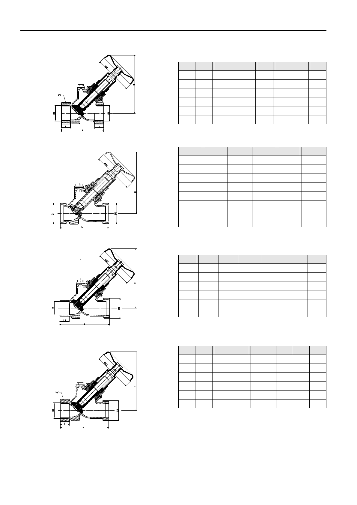
Dimensions (all dimensions in mm unless otherwise stated)
Fig. 1. Alwa-Valve with internal threads
Fig. 2. Alwa-Valve with external threads
Fig. 3. Alwa-Valve with soldering connection on inlet and
external thread with nut and soldering tailpiece on outlet
Table 1. Dimensions Alwa-Valve with internal threads
DN kvs D1 D2 H L SW t
15 6,3 R 1/2” 50 95 65 27 15,0
20 14,4 R 3/4” 50 105 75 32 16,3
25 23,0 R 1” 80 125 90 41 19,1
32 43,4 R 1 1/4” 80 145 110 50 21,4
40 54,4 R 1 1/2” 80 160 120 55 21,4
50 81,0 R 2” 80 185 150 70 25,7
Table 2. Dimensions Alwa-Valve with external threads
DN kvs D1 D2 H L
15 6,3 G 3/4” 50 95 70
20 13,4 G 1” 50 105 81
25 21,6 G 1 1/4” 80 125 98
32 37,0 G 1 1/2” 80 145 117
40 51,6 G 1 3/4” 80 160 130
50 81,0 G 2 3/8” 80 185 152
65 132 G 3” 120 230 205
80 193 G 3 1/2” 120 255 234
Table 3. Dimensions Alwa-Valve with soldering
connection on inlet and external thread with nut and
soldering tailpiece on outlet
DN kvs D1 D2 D3 H L
15 6,3 15 50 G 3/4” 95 70
20 13,4 22 50 G 1” 105 89
25 21,6 28 80 G 1 1/4” 125 104
32 37,0 35 80 G 1 1/2” 145 128
40 51,6 42 80 G 1 3/4” 160 142
50 81,0 54 80 G 2 3/8” 185 169
Table 4. Dimensions Alwa-Valve with internal thread on
inlet and external thread on outlet
DN kvs D1 D2 D3 H L SW
15 6,3 R 1/2” 50 G 3/4” 95 71,5 27
20 14,4 R 3/4” 50 G 1” 105 84,5 32
25 23,0 R 1” 80 G 1 1/4” 125 102 41
32 40,0 R 1 1/4” 80 G 1 1/2” 145 122 50
40 51,9 R 1 1/2” 80 G 1 3/4” 160 134 55
50 85,4 R 2” 80 G 2 3/8” 185 160 70
Fig. 4. Alwa-Valve with internal thread on inlet and
external thread on outlet
EN0H-0139GE25 R0105 2 Honeywell GmbH • All rights reserved
Page 3

V4000 ALWA-VALVE
Fig. 5. Alwa-K with external threads for plastic pipe
Table 5. Dimensions Alwa-K with external threads for
plastic pipe
DN kvs D1 D2 H L
15 6,3 G 1” 50 95 70
20 13,4 G 1 1/4” 50 105 81
25 21,6 G 1 1/2” 80 125 98
32 37,0 G 2” 80 145 117
40 51,6 G 2 1/4” 80 160 130
50 81,0 G 2 3/4” 80 185 152
Table 6. Dimensions Alwa-F with flanges
DN kvs L t A A1 H D2
15 6,3 130 10 95 45 95 50
20 14,4 150 11 105 58 105 50
25 23,0 160 11 115 68 125 80
32 40,0 180 12 140 78 145 80
40 51,5 200 12 150 88 160 80
50 85,4 230 14 165 102 185 80
65 132,0 290 14 185 122 240 120
80 193,0 310 15 200 138 265 120
100 251,0 350 18 220 158 410 140
125 320,0 400 26 250 188 415 225
150 460,0 480 26 285 212 505 250
Fig. 6. Alwa-F with flanges
Honeywell GmbH • All rights reserved 3 EN0H-0139GE25 R0105
Page 4

V4000 ALWA-VALVE
Ordering information
Table 7. Ordering information and OS-Nos. (OS = ordering system)
Ordering text OS-No. DN 15 20 25 32 40 50 65 80 100 125 150
mm 15 18 22 28 35 42 54 — — — — —
R 1/2” 3/4” 3/4” 1” 1 1/4” 1 1/2” 2” 2 1/2” 3” 4” 4 1/2” 5”
Alwa-Valve with internal threads -
- closed valve body V4000YY... 020 025 032 040 050
- with blind plug V4020YY... 015 018 020 025 032 040 050
Alwa-Valve with external threads -
- with blind plug V4020XX... 015 020 025 032 040 050 065 080
Alwa-Valve with internal thread on inlet and external thread on outlet -
- with blind plug V4010YX... 015 020 025 032 040 050
Draining valve, with cap
and chain
Alwa-Valve with soldering connection on inlet and external thread with nut and soldering tailpiece on outlet -
- with blind plug V4020SS... 015 018 020 025 032 040 050
Alwa-K valve for plastic pipe -
- with blind plug V4020KK... 015 020 025 032 040 050
Alwa-F valve with flanges -
- closed valve body V4020FF... 100 125 150
- with blind plug V4020FF... 015 020 025 032 040 050 065 080
V4019XY... 015 020
EN0H-0139GE25 R0105 4 Honeywell GmbH • All rights reserved
Page 5

Accessories
Connections for external threads
Union nut, sealing and red bronze soldering tailpiece for external
threads
DN15, for 15 mm pipe-Ø VA7400A015
DN15, for 18 mm pipe-Ø VA7400A016
DN20, for 18 mm pipe-Ø VA7400A018
DN20, for 22 mm pipe-Ø VA7400A020
DN25, for 28 mm pipe-Ø VA7400A025
DN32, for 35 mm pipe-Ø VA7400A032
DN40, for 42 mm pipe-Ø VA7400A040
DN50, for 54 mm pipe-Ø VA7400A050
DN65, for 64 mm pipe-Ø VA7400A064
DN65, for 70 mm pipe-Ø VA7400A070
DN80, for 76 mm pipe-Ø VA7400A076
DN80, for 80 mm pipe-Ø VA7400A080
DN80, for 89 mm pipe-Ø VA7400A089
Union nut, sealing and externally threaded red bronze tailpiece for
external threads
for DN15 VA7401A015
for DN20 VA7401A020
for DN25 VA7401A025
for DN32 VA7401A032
for DN40 VA7401A040
for DN50 VA7401A050
for DN65 VA7401A065
for DN80 VA7401A080
Union nut with MAPRESS-fitting for external threads
DN15, for 15 mm pipe-Ø VA7403A015
DN15, for 18 mm pipe-Ø VA7403A018
DN20, for 22 mm pipe-Ø VA7403A020
DN25, for 28 mm pipe-Ø VA7403A025
DN32, for 35 mm pipe-Ø VA7403A032
DN40, for 42 mm pipe-Ø VA7403A040
DN50, for 54 mm pipe-Ø VA7403A050
DN65, for 70 mm pipe-Ø VA7403A065
DN80, for 89 mm pipe-Ø VA7403A080
V4000 ALWA-VALVE
Union nut with Sanpress-fitting for external threads
DN15, for 15 mm pipe-Ø VA7404A015
DN15, for 18 mm pipe-Ø VA7404A018
DN20, for 22 mm pipe-Ø VA7404A020
DN25, for 28 mm pipe-Ø VA7404A025
DN32, for 35 mm pipe-Ø VA7404A032
DN40, for 42 mm pipe-Ø VA7404A040
DN50, for 54 mm pipe-Ø VA7404A050
Union nut, sealing and internally threaded red bronze tailpiece for
external threads
for DN15 VA7405A015
for DN20 VA7405A020
for DN25 VA7405A025
for DN32 VA7405A032
for DN40 VA7405A040
for DN50 VA7405A050
Brass hose connection for draining valves
for DN15 VA7406A015
for DN20 VA7406A020
Draining valve
from DN15 to DN25 VA3401A008
from DN32 to DN80 VA3401A010
Service parts
Handwheel, green
for DN15 to DN20 VS2400A050
for DN25 to DN50 VS2400A080
for DN65 to DN80 VS2400A120
Valve insert for all valve housing according to DVGW
for valve housings DN15 VS1400A015
for valve housings DN20 VS1400A020
for valve housings DN25 VS1400A025
for valve housings DN32 VS1400A032
for valve housings DN40 VS1400A040
for valve housings DN50 VS1400A050
for valve housings DN65 VS1400A065
for valve housings DN80 VS1400A080
Honeywell GmbH • All rights reserved 5 EN0H-0139GE25 R0105
Page 6

V4000 ALWA-VALVE
Automation and Control Products
Honeywell GmbH Phone: (49) 2932 9880
Zu den Ruhrwiesen 3 Fax: (49) 2932 988224 http://www.alwa-valves.com
D-59755 Arnsberg-Neheim mng@honeywell.com http://europe.hbc.honeywell.com
EN0H-0139GE25 R0105 6 Subject to change • All rights reserved
 Loading...