

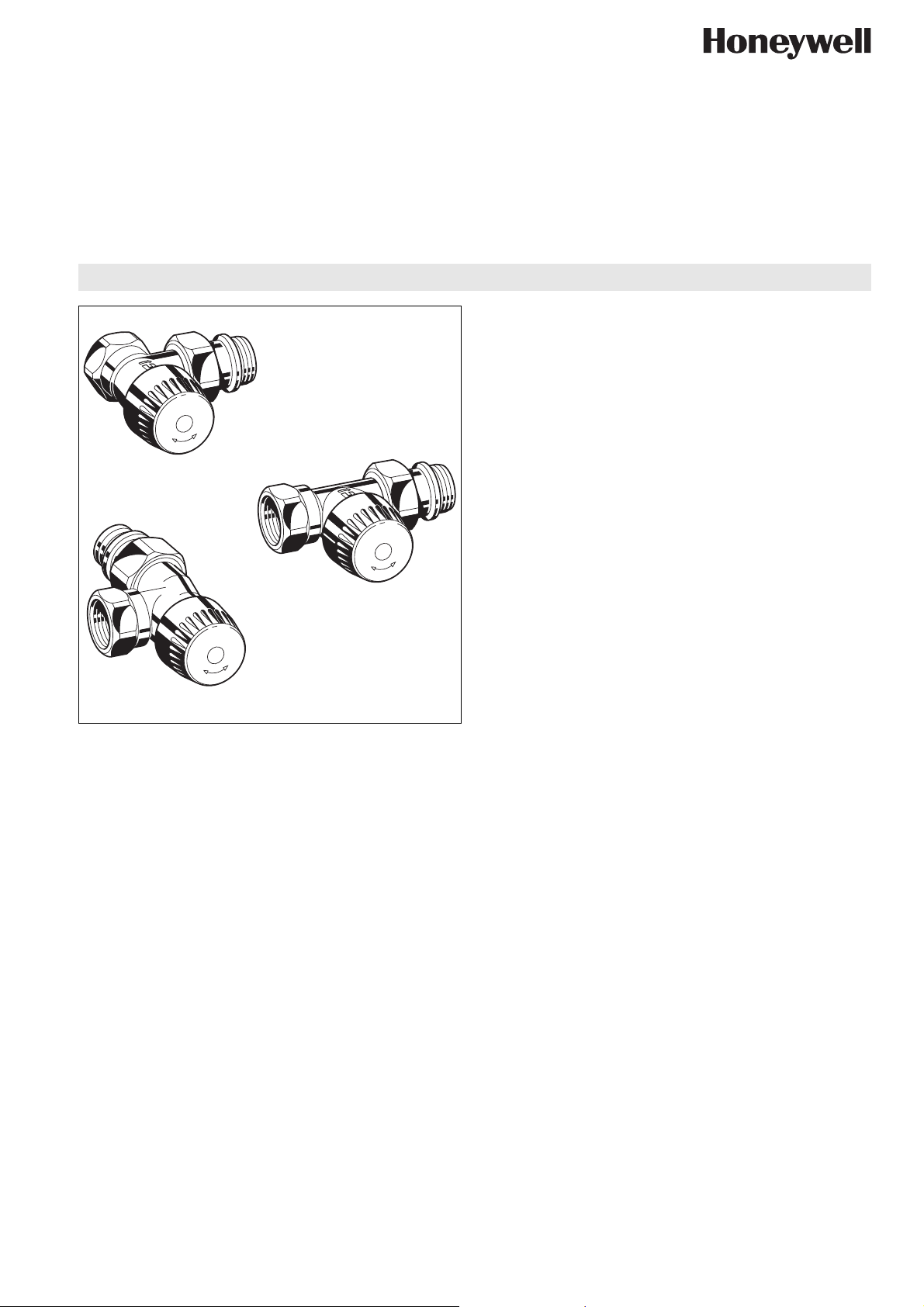
Angle
Horizontal angle
V320
VENUS Series TRV Body
TRV BODY WITH STROKE LIMITATION, INTERNAL THREADS
PRODUCT DATA
Application
Thermostatic radiator valve bodies (TRV bodies) are fitted on
the supply or return of radiators or heat exchangers. Together
with a radiator thermostat, for example the Thera-4, they
control the room temperature by regulating the flow of hot water
into the radiator. The temperature of different rooms is
controlled individually and energy is saved.
TRV bodies of this type have quiet operation and are fitted to
the supply or return of radiators on two-pipe systems with medium flow rates.
The valve insert can be replaced while the system is running
and without draining using the service tool (see ‘Accessories’).
TRV bodies of this type are suitable for
• Honeywell radiator thermostats with M30 x 1.5 connection
Straight
• Certain Honeywell MT4 actuators
• Honeywell Hometronic HR80 and Roomtronic HR40 actuators
The VENUS Series is supplied with a protection cap. To convert
the VENUS Series to thermostatic operation the protection cap
is replaced by a radiator thermostat, e.g. Honeywell Thera-4.
Design
The thermostatic radiator valve bodies consist of:
• Valve housing PN10, DN10 or DN15 with
• internal thread connection to ISO228 on inlet
• external thread connection with union-nut and radiator tailpiece on outlet
• angle and straight bodies with dimensions according so
EN215, Appendix A, Series F
• Pre-settable valve insert
• Protection cap
Materials
• Valve housing made of nickel-plated brass
• Valve insert made of brass with EPDM O-rings and soft seals
and stainless steel spindle
• Protection cap made of plastic
• Union-nut and tailpiece made of nickel plated brass with
EPDM O-ring
Features
• Supplied with protection cap
• Bi-directional flow
• Pre-settable by stroke limitation
• For 1- and 2-pipe systems
• Standard M30 x 1.5 thermostat connection
• Connection to all types of pipework DN10 to DN15
• Quiet operation
• Tail piece with integrated O-ring
Specifications
Medium Heating water, water quality to
VDI2035
ph-value 8...9.5
Operating temperature max. 120°C (248°F)
Operating pressure PN10
Differential pressure max. 0.2 bar (2.9 psi)
recommended for quiet operation
k
(cv)-values DN10 1.70 (1.99)
vs
DN15 1.85 (2.16)
Thermostat connection M30 x 1.5
Closing dimension 11.5 mm
Stroke 2.5
Honeywell y Subject to change EN0H-2117GE25 R1106
V320 - VENUS SERIES TRV BODY
Function
Thermostatic radiator valves enable individual control of room
temperature and thus save energy.
The TRV body is controlled by the radiator thermostat. Air from
the room passing over the sensor of the radiator thermostat
causes the sensor to expand when the temperature rises. The
sensor acts onto the valve spindle and this causes the TRV
body to close. When the temperature falls the sensor contracts
and the spring-loaded valve spindle is opened. The TRV opens
in proportion to the temperature of the sensor. Only the amount
Please Note:
• To avoid stone deposit and corrosion the composition of the
medium should conform with VDI-Guideline 2035
• Additives have to be suitable for EPDM sealings
• System has to be flushed thoroughly before initial operation
with all valves fully open
• Any complaints or costs resulting from non-compliance with
above rules will not be accepted by Honeywell
• Please contact us if you should have any special requirements or needs
of water required to maintain the room temperature set on the
radiator thermostat can flow into the radiator.
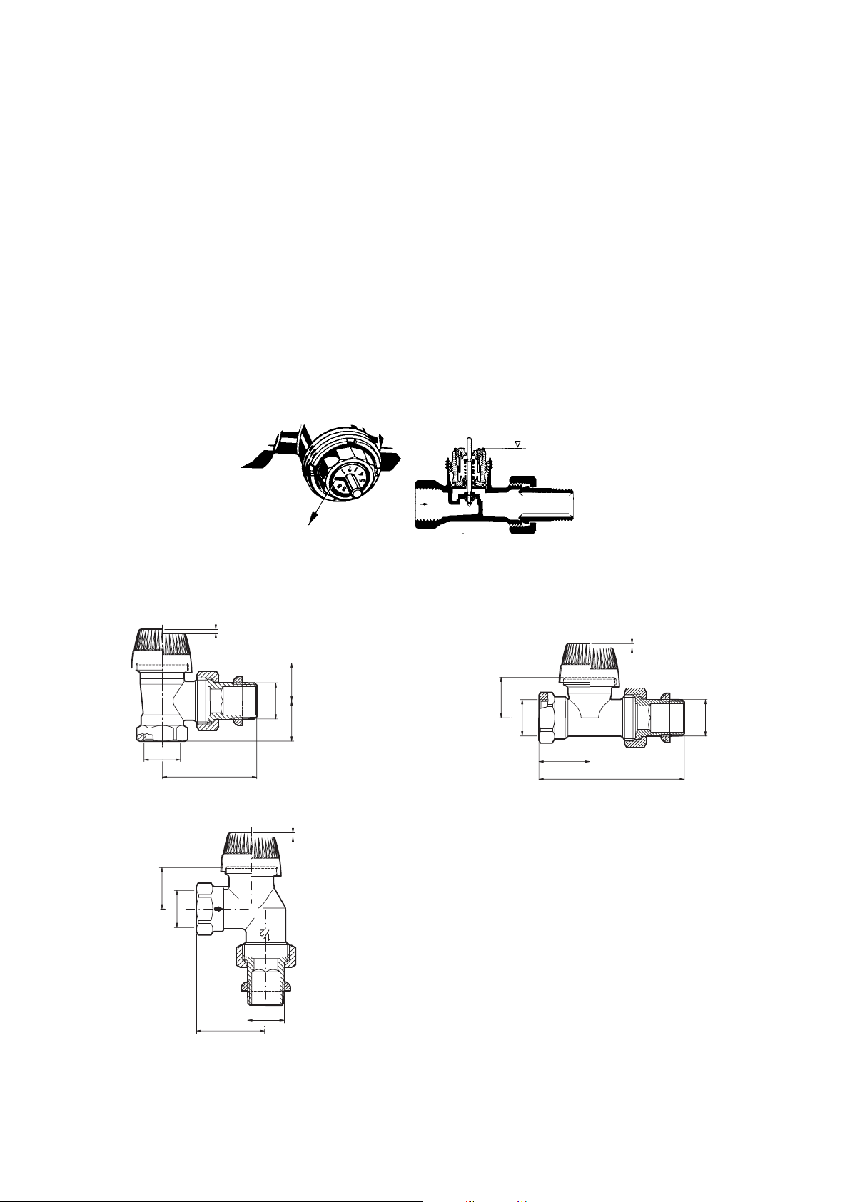
Setting procedure
Turn the pre-setting screw until stop. Mark position of screwdriver slot as reference point. Then turn anticlockwise according to
reference figure obtained from the pressure drop chart.
Reference figure 10 corresponds to 1 turn.
Reference figure 20 corresponds to 2 turns.
flush
Dimensions
Screwdriver slot for
adjustment of
presetting screw
2.5
hl1
d1
d2
l
h
d2
l1
Fig. 1. Angle Fig. 2. Straight
2.5
h
d2
Position of pre-setting
screw at delivery
2.5
d1
l
d1
l
Fig. 3. Horizontal angle
EN0H-2117GE25 R1106 2 Honeywell y Subject to change
 Loading...