

Page 1

DVR Installation Manual
V2.X
HRGX Series DVR’s
Page 2

Table of Contents
WORKFLOW ...................................................................................................................................................................... 3
INSTALLATION WORKSHEET ...................................................................................................................................... 4
Default DVR Login ............................................................................................................................................................................. 4
NETWORK SETUP (UPNP) ............................................................................................................................................ 5
NETWORK SETUP (NON - UPNP) ................................................................................................................................ 8
DYNAMIC IP ADDRESS ................................................................................................................................................. 11
ROUTER SETTINGS & PORT FORWARDING .......................................................................................................... 12
SMTP SETTINGS ............................................................................................................................................................. 13
USER SETTINGS .............................................................................................................................................................. 14
RECORDING SETUP ....................................................................................................................................................... 15
Scheduled Recording Mode ............................................................................................................................................................. 16
Event Recording Mode .................................................................................................................................................................... 19
ALARM INPUT SETUP ................................................................................................................................................... 21
MOTION DETECTION SETUP ...................................................................................................................................... 23
CONFIGURE I-VIEW NOW ENTRY DELAYS ............................................................................................................. 23
TEST SETTINGS .............................................................................................................................................................. 24
Picture Clarity .................................................................................................................................................................................. 24
APPENDIX A – REQUIRED PARAMETERS ............................................................................................................... 25
Honeywell HRGX Series Installation Guide rev 2.X I-View Now, LLC. All Rights Reserved. © 2014 Page 2
Page 3
Workflow
a. Does the customer have a UPnP enabled router? If so, skip b through d. Go to step 2.
b. What is the external IP address of the customer?
c. Is the external IP address static or dynamic?
d. Are ports 8000, 8001, 8002 open through the router?
2. Configure SMTP email: This will be used to communicate alerts and alarms to I-View Now. The SMTP server
and SMTP ID provided on the “Installer Data” Worksheet will be used here
3. User Setup: Change the default administrator password. I-View Now will be using this password to log into
the device. I-View Now suggests using the suggested password on the “Installer Data” worksheet.
4. Recording Setup: The DVR will be set to record by schedule or by events. Event recording will only record
when either a motion or alarm event is detected. Scheduled recordings occur during the scheduled time.
5. Alarm Input Setup: Here the technician will be setting up the alarm inputs on the back of the DVR to
perform two actions: 1) Trigger recording on all connected cameras. And most importantly, 2) Send SMTP
(email) alert to I-View Now upon the event of an alarm.
6. Motion Detection Setup: activate video motion recording for desired cameras.
7. Configure I-View Now Entry Delay: Entry delay is configured through the I-View Now portal.
8. Test: Here you will test the individual inputs on the DVR as they are connected to your alarm panel relays or
other input devices. It is recommended that you test all inputs for functionality and to ensure the proper
workflow is configured within the i-viewnow.com portal.
9. Trouble Shooting: This section is provided to help the technician troubleshoot common problems
encountered while installing HRG series DVR’s
1. Network Setup: Determine the following network parameters.
THE FOLLOWING INFORMATION IS REQUIRED FOR THE INSTALLATION. FOR GUIDELINES ON
HOW TO OBTAIN THE FOLLOWING INFORMATION, PLEASE SEE APPENDIX A.
Honeywell HRGX Series Installation Guide rev 2.X I-View Now, LLC. All Rights Reserved. © 2014 Page 3
Page 4
Installation Worksheet
USB Mouse
VGA Cable
VGA Port
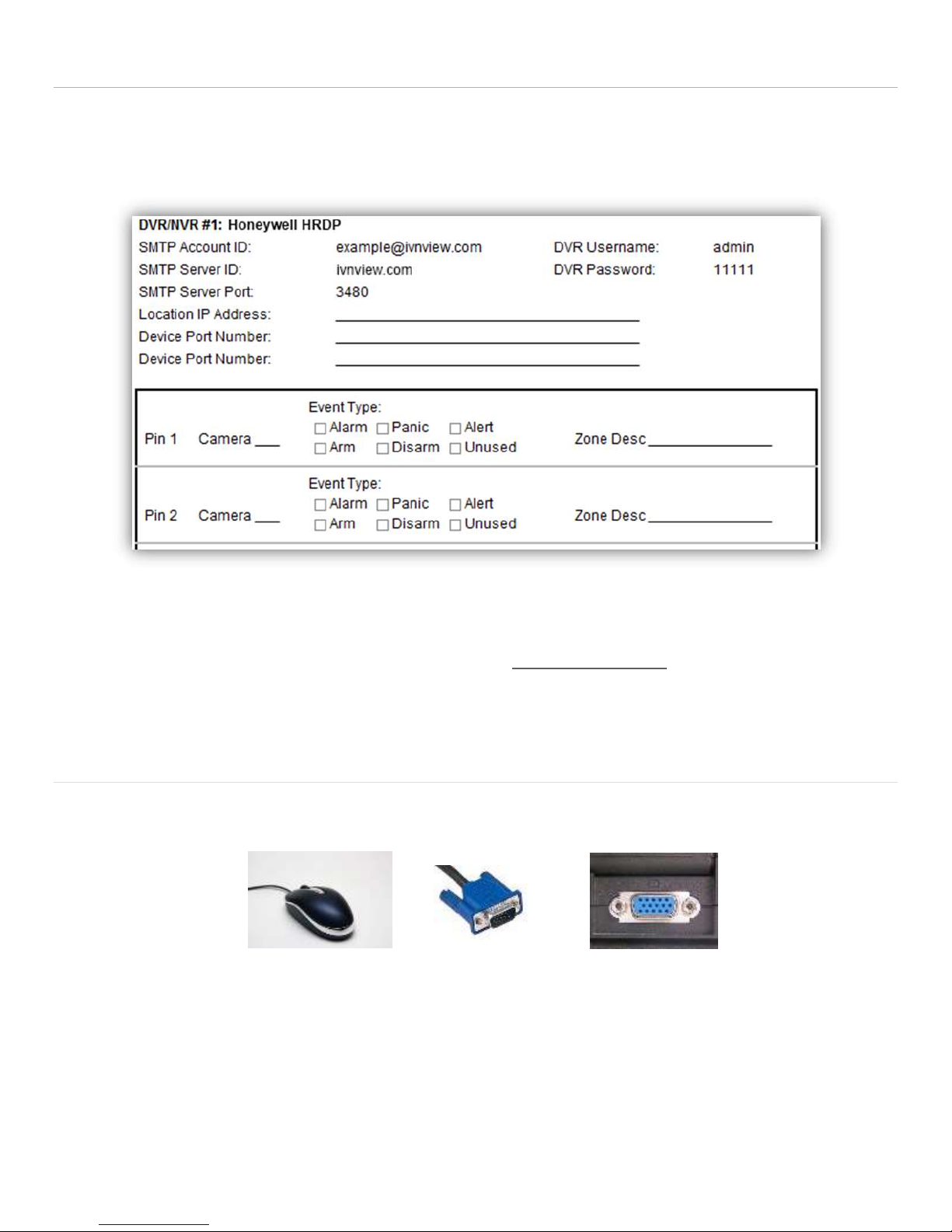
The I-View Now Portal will provide an Installation Worksheet after entering the DVR make and model into the system.
This sheet will contain configuration information for the DVR’s notifications area, and provides a form to fill in details
about the site setup (alarms, zone names). An example worksheet is printed below.
You will only need to retrieve the IP address while on-site if the installation will NOT utilize the UPnP functionality.
Either ask the customer/IT department for the IP address, or visit http://whatismyip.org while on-site for the correct
address.
Default DVR Login
Plug a monitor into the VGA output on the DVR. Also, plug the mouse provided with the DVR into the front side USB port
of the DVR unit. The mouse must be plugged in before the DVR is turned on, or the DVR will not recognize it.
User Name: admin
Password: 12345
Honeywell HRGX Series Installation Guide rev 2.X I-View Now, LLC. All Rights Reserved. © 2014 Page 4
Page 5
Network Setup (UPnP)
THIS SECTION IS FOR UPnP ENABLED ROUTERS ONLY
SKIP THIS SECTION IF THE ROUTER DOES NOT HAVE UPnP ENABLED
If the router has UPnP enabled, there will be no
need to port forward or provide the IP address.
This information will automatically be sent to
the I-View Now system by UPnP.
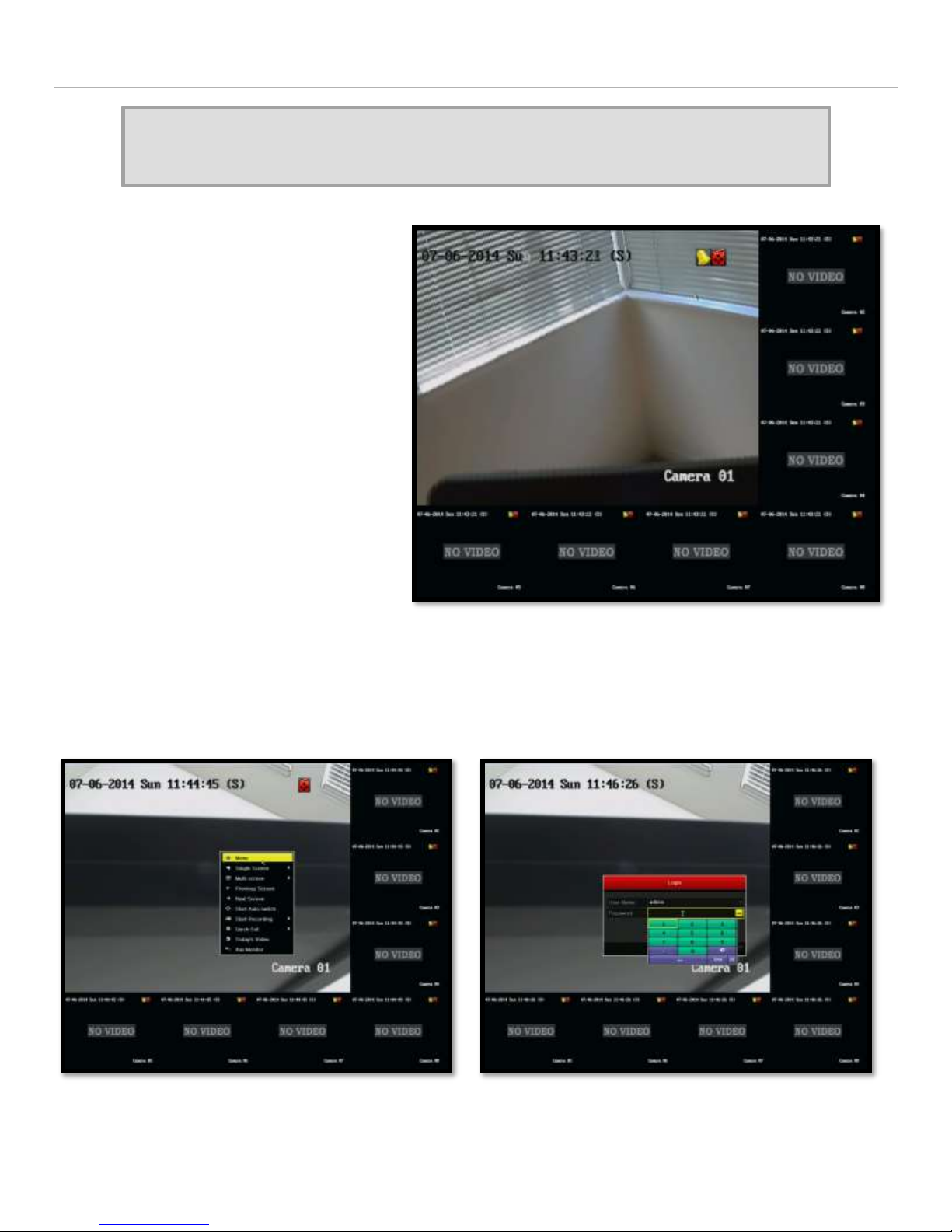
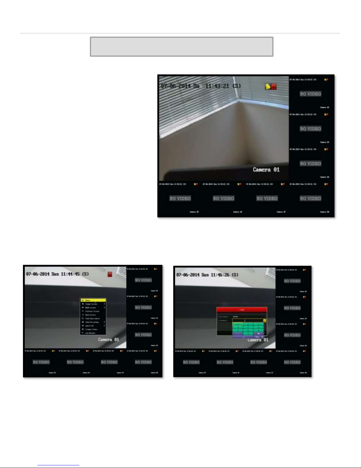
Once the DVR is turned on, the first screen that
will be shown shows the connected cameras
and also serves as the entry point to other
functions.
Right click on the screen and select “Menu” from the list. Click in the password box and use the virtual keyboard to
enter the password. Click on “Enter” when complete and then click “OK”.
Honeywell HRGX Series Installation Guide rev 2.X I-View Now, LLC. All Rights Reserved. © 2014 Page 5
Page 6
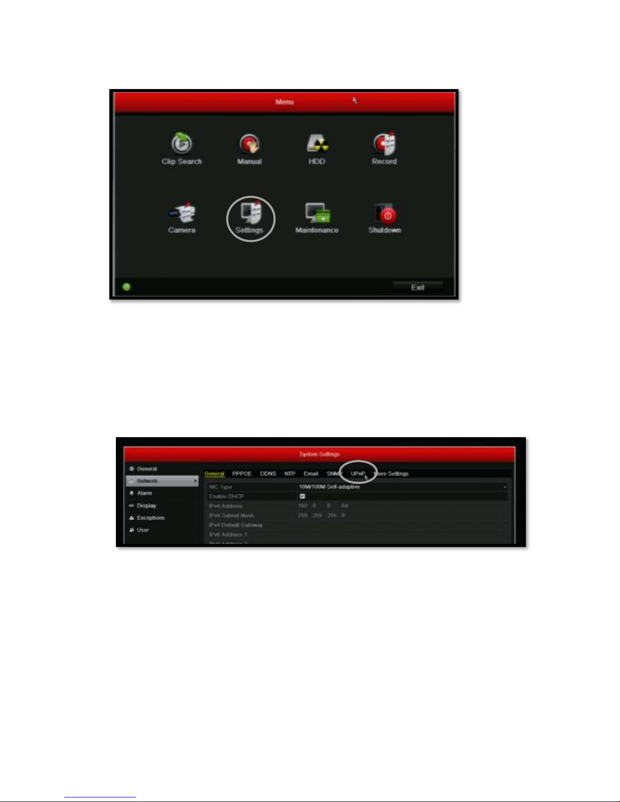
After logging into the system, the main menu will appear.
Click on “Settings”.
Setting up UPnP
In order to configure the device for use with I-View Now, UPnP must be enabled. Click on the “Network” menu item on
the left side of the screen.
After clicking on “Network”, the sub-menus will show at the top of the screen. The second to the last option says
“UPnP”. Click on this menu item.
Honeywell HRGX Series Installation Guide rev 2.X I-View Now, LLC. All Rights Reserved. © 2014 Page 6
Page 7
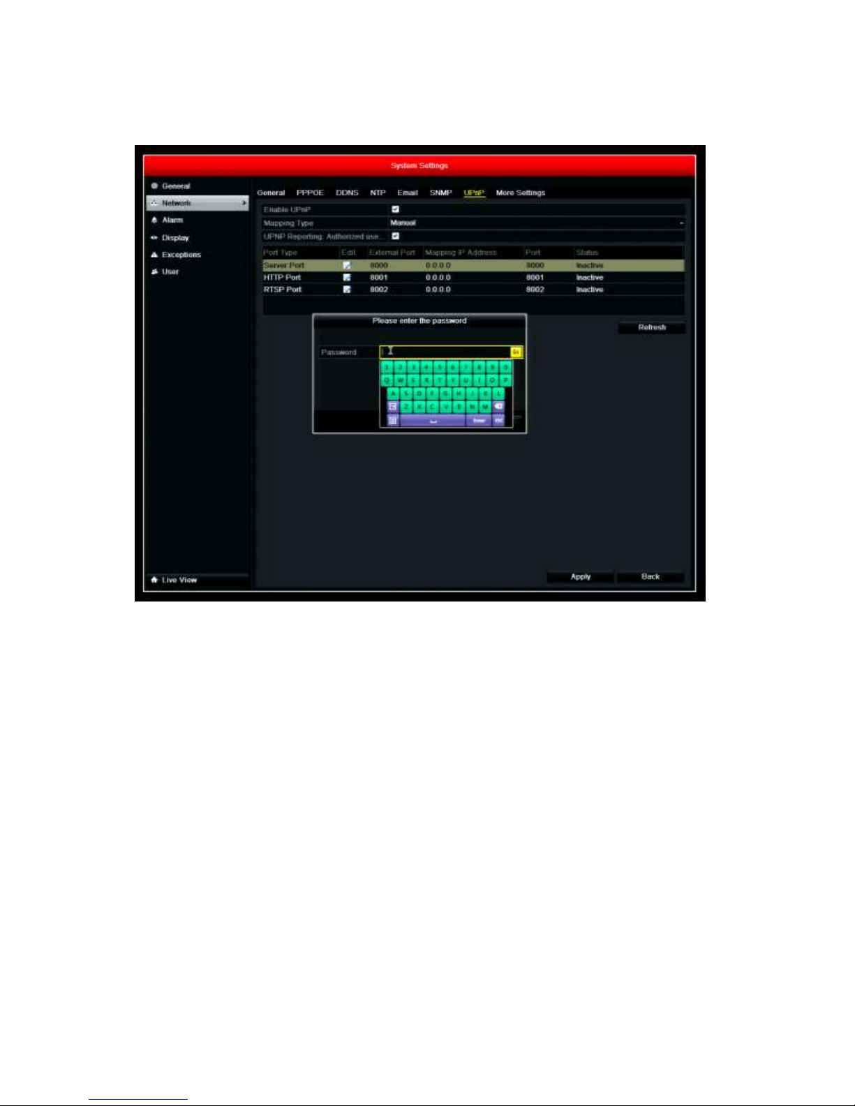
Once within the UPnP menu, perform the following.
1. Enable UPnP by clicking in the box to the right of “Enable UPnP”.
2. Set Mapping Type to “Manual”
3. Enable UPnP Reporting Authorized use by clicking in the box to the right of “UPnP Reporting Authorized use”
a. A password is required to enable this required function
b. Click in the box where the password will be entered
c. Using the virtual keyboard, enter “iview123” (no quotes).
d. Select “Enter”, then “OK”.
4. Set the Server port to 8000
5. Set the HTTP Port to 8001
6. Set the RTSP Port to 8002
7. Click “Apply” at the bottom right of the screen.
8. UPnP Reporting is now enable and the DVR will begin reporting its IP address and ports to the I-View Now
Server. The initial reporting could take up to 5 minutes and can only be tested after completing the SMTP
configuration section.
Honeywell HRGX Series Installation Guide rev 2.X I-View Now, LLC. All Rights Reserved. © 2014 Page 7
Page 8
Network Setup (Non - UPnP)
SKIP THIS SECTION IF UPnP IS ENABLED
If the router does not have UPnP enabled,
consideration needs to be given to whether the
site has a static or dynamic IP address and
whether the router has blocked the ports to the
DVR. The following steps will describe the
required actions depending on the configuration
of the customer’s environment.
Once the DVR is turned on, the first screen
shows the connected cameras and also serves as
the entry point to other functions.
Right click on the screen and select “Menu” from the list. Click in the password box and use the virtual keyboard to
enter the password. Click on “Enter” when complete.
After logging into the system, the main menu will appear.
Honeywell HRGX Series Installation Guide rev 2.X I-View Now, LLC. All Rights Reserved. © 2014 Page 8
Page 9
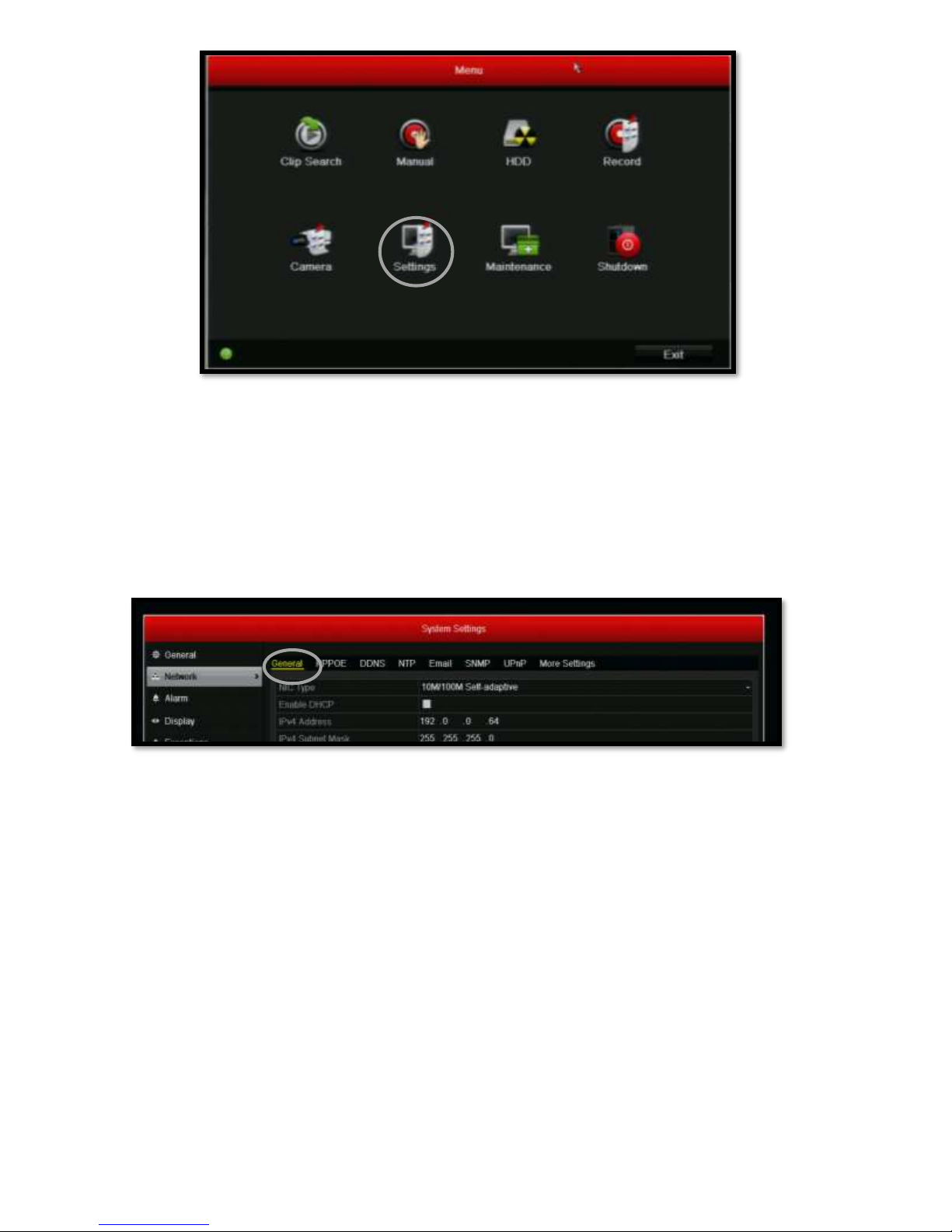
Click on “Settings”.
Configuring the IP Address
In order to configure the device for use with I-View Now, the first settings that should be changed are located under the
Network menu and General sub-menu. Click on the “Network” menu item on the left side of the screen.
After clicking on “Network”, the submenus will show at the top of the screen. The first sub-menu item says “General”.
Click on this menu item.
Honeywell HRGX Series Installation Guide rev 2.X I-View Now, LLC. All Rights Reserved. © 2014 Page 9
Page 10
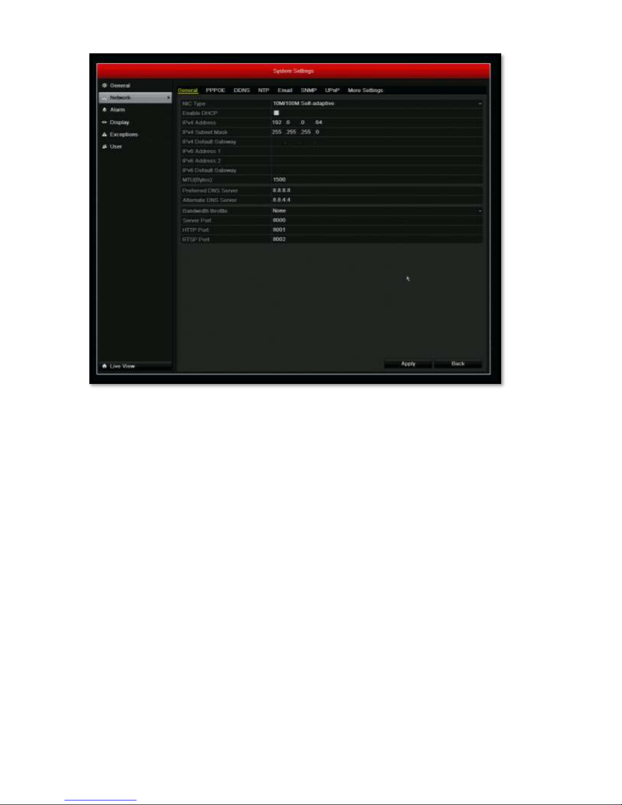
Once within the General menu, several tasks will need to be performed.
1. Uncheck “Enable DHCP”
2. Enter a static internal IP in the IPv4 Address field and the Subnet Mask in the IPv4 Subnet Mask field. Note that
this is NOT the external IP address of the customer, but an internal IP address.
3. If the site’s IT staff has a preferred DNS Server and Alternate DNS Server, enter these in the designated areas. If
not, Google’s public DNS servers are typically used. Google’s IPs are 8.8.8.8 for the preferred DNS Server and
8.8.4.4 for the Alternate DNS Server.
4. Set the server port to 8000
5. Set HTTP Port to 8001
6. Set the RTSP Port to 8002
7. Click “Apply” at the bottom right of the screen.
Honeywell HRGX Series Installation Guide rev 2.X I-View Now, LLC. All Rights Reserved. © 2014 Page 10
Page 11
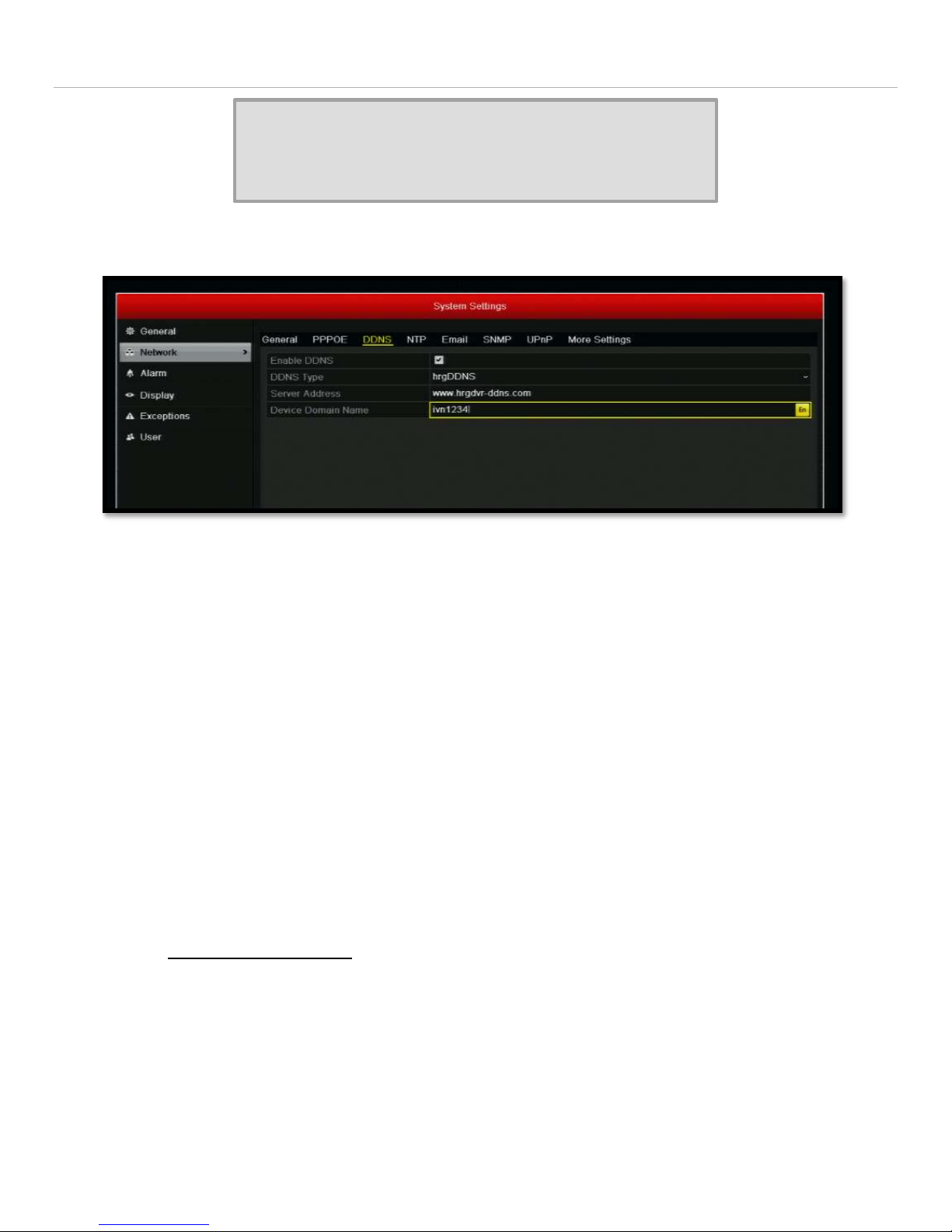
Dynamic IP Address – Optional
SKIP THIS SECTION IF UPnP IS ENABLED OR
IF THE IP ADDRESS IS STATIC
This section describes how to configure Honeywell’s DDNS Service and will be required if the site does not have a static
external IP address.
Go to the Network Menu
Click on the DDNS submenu
Check “Enable DDNS”
Enter site name that will be used to register this customer with Honeywell’s service. The name must start with a
letter and can contain letters and numbers.
Write down this name as it will need to be forwarded to the representative configuring I-View Now at the
Central Station.
Select Apply.
Provide the following URL to the central station representative assisting with the configuration:
hrgdvr-ddns.com/”Site Name”
o For example, if you named the site ivn1234, provide the URL :
hrgdvr-ddns.com/ivn1234
This URL will be entered into the I-View Now Portal by the central station representative as the site’s IP
address.
Honeywell HRGX Series Installation Guide rev 2.X I-View Now, LLC. All Rights Reserved. © 2014 Page 11
Page 12
Router Settings & Port Forwarding - Optional
SKIP THIS SECTION IF UPnP IS ENABLED OR
IF THE ROUTER PORTS ARE OPEN
Router settings must be examined on a case by case basis. I-View Now requires three ports to be forwarded to the
Device. This can be done either through port forwarding or NAT (Network Address Translation) depending on what the
installation site’s router supports. With either of these router features, any unused/unfiltered External Port can be
forwarded to the Server Port which is sometimes known as the Video Port. It is recommend that the ports are forwarded
without translation. E.g. internal port 8000 is forwarded to the DRV port 8000, internal port 8001 is forwarded to the
DRV port 8001, and internal port 8002 is forwarded to the DRV port 8002.
Regardless of the port forwarding configuration, it is the External IP Address and External Port numbers that must be
entered into the I-View Now “Installer’s Portal.”
If ports are not forwarded, typical behavior will be that I-View Now and the Central Station receives the alarm signal, but
no video is associated with the video as the blocked ports are preventing I-View Now from reaching back into the device.
For information on how to port forward, see Appendix A.
Note: Any ports used must be unblocked in any firewall devices (typically just the router).
Honeywell HRGX Series Installation Guide rev 2.X I-View Now, LLC. All Rights Reserved. © 2014 Page 12
Page 13
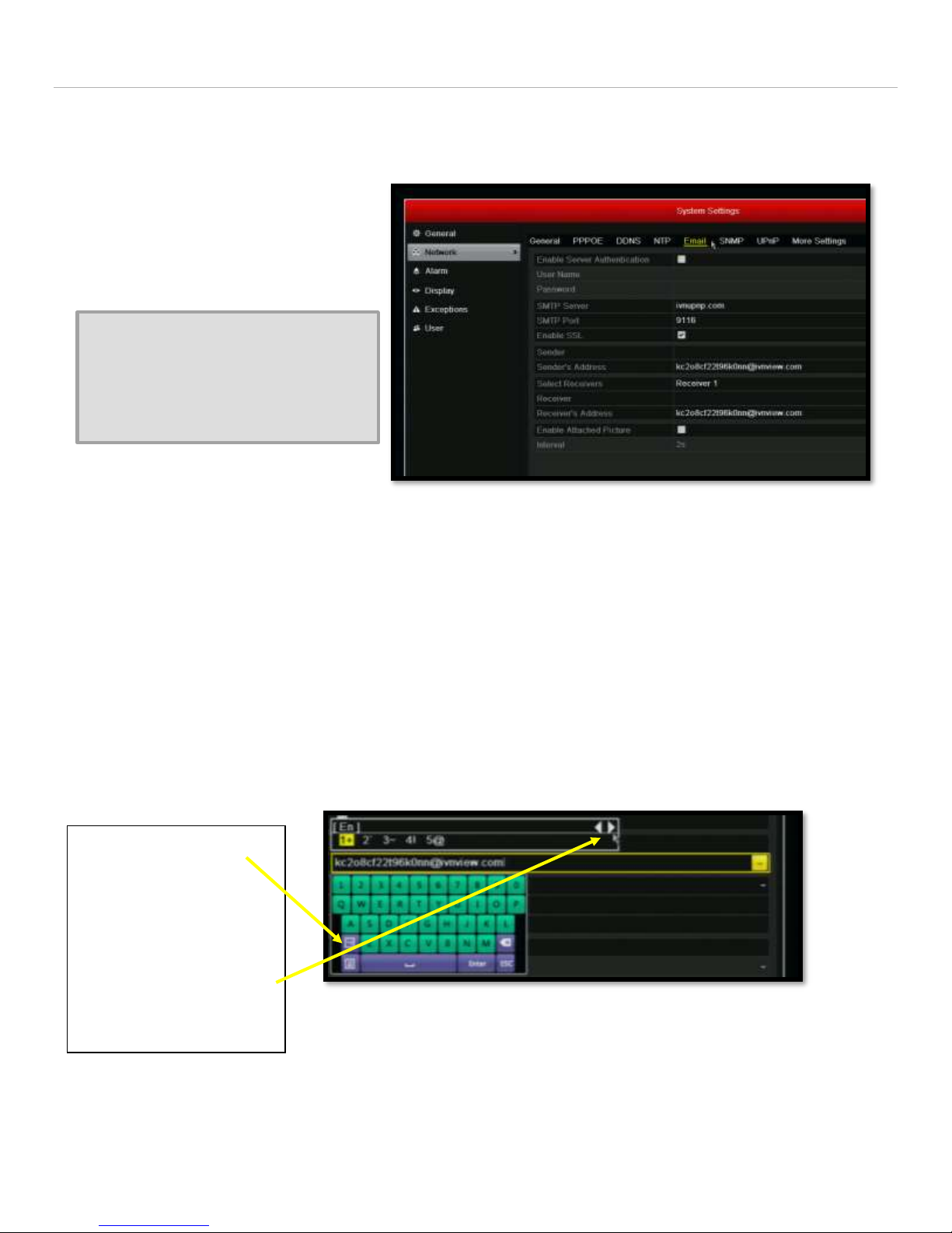
SMTP Settings
Network-> Email
1. Click on Special
characters key
2. Scroll to the right
until finding the @
symbol. Click on
symbol to insert it.
This section describes how to set up SMTP on the DVR to allow Alarm notifications to be sent to I-View Now.
From the Network Menu:
Click on the Email submenu
Uncheck Enable Server
Authentication
Check the “Enable SSL”
For UPnP enter ivnupnp.com in the
SMTP Server Field
OR
For Non-UPnP enter ivnview.com in
the SMTP Server Field
Enter 9116 in the SMTP Port
From the “Installation Worksheet”
Enter the SMTP ID into the Sender’s Address Field and into the Receiver’s Address
A Picture showing how to Enter the @
symbol is on the next page.
Press Test at the bottom of the page. The
dialog box should indicate a successful test.
Press Apply
Within 5 minutes, the central station representative should now see the DVRs IP address and ports updated in
the I-View Now portal.
NOTE:
Special characters such as the @ symbol can be accessed by the clicking on the special characters virtual key.
Honeywell HRGX Series Installation Guide rev 2.X I-View Now, LLC. All Rights Reserved. © 2014 Page 13
Page 14
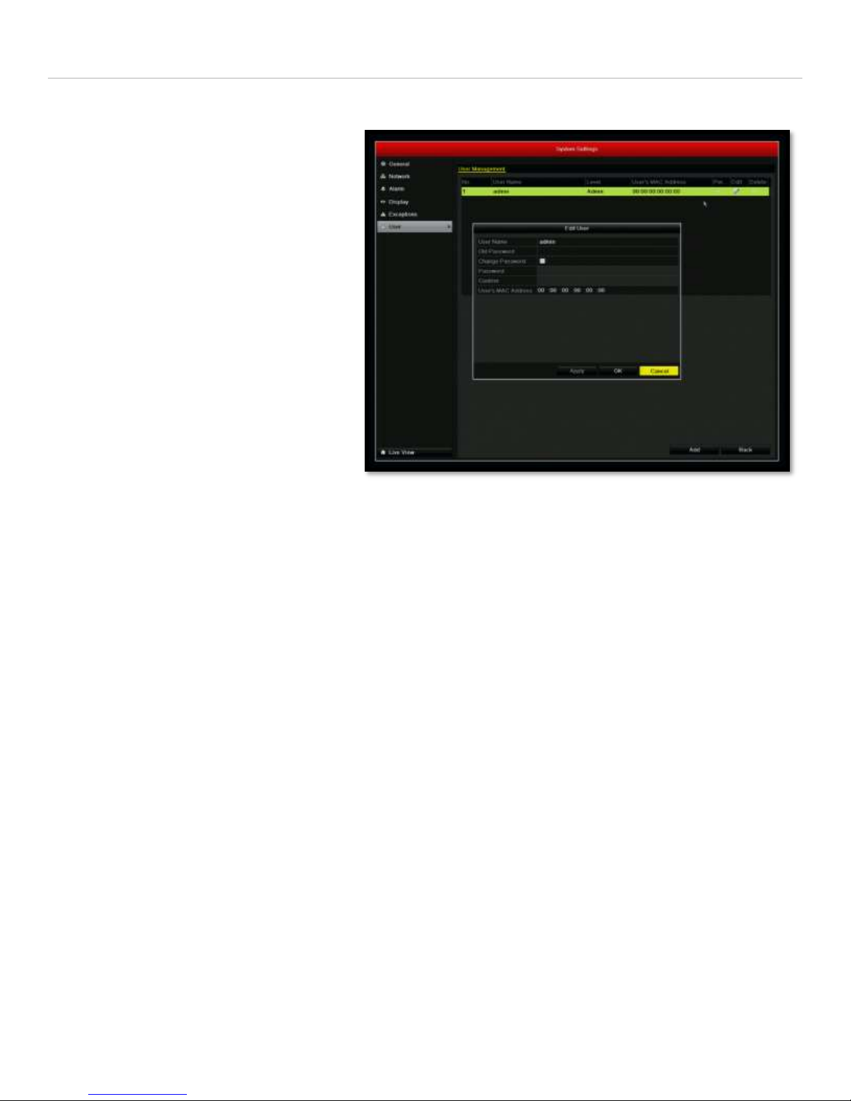
User Settings
System Settings Menu
User Settings
This section explains how to change the DVR’s password
Main Menu-> Settings->User
Click the edit symbol on the admin user
This will bring you to the Edit User
screen.
Check the Change Password box
Enter the Old Password(Default 12345)
Enter the desired Password
Confirm the desired Password
Click “Apply”
If using a password other than the
suggested password from the Installer’s
Worksheet, note the new password for
entry into the I-View Now Installer’s
Portal
I-View Now Suggests not using the
default password.
Additional Users can be configured with the
add button.
Honeywell HRGX Series Installation Guide rev 2.X I-View Now, LLC. All Rights Reserved. © 2014 Page 14
Page 15
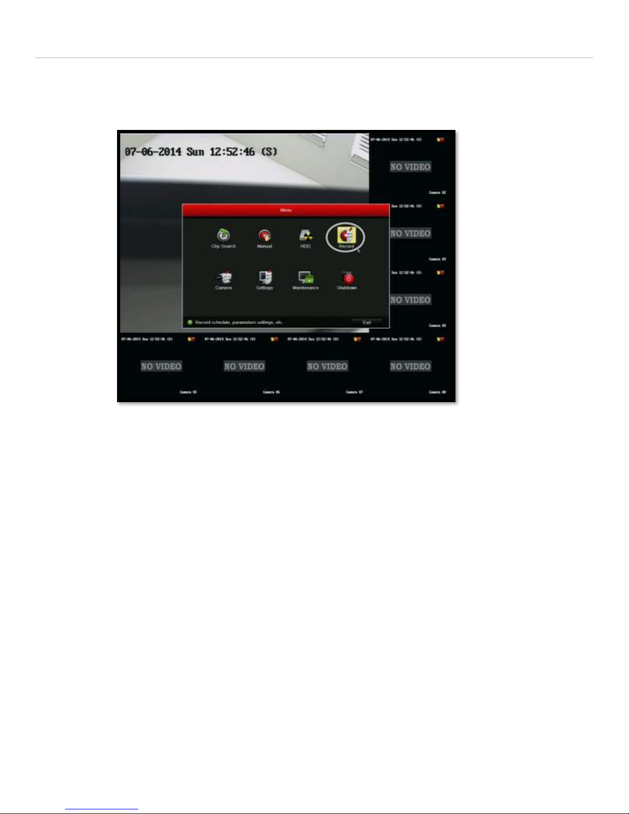
Recording Setup
For the HRG to send clips to I-View Now, the recording parameters must be configured. To access the recording
parameters, go to the main menu and select “Record”.
Configuration details for both event based recording and scheduled recording are detailed next.
Honeywell HRGX Series Installation Guide rev 2.X I-View Now, LLC. All Rights Reserved. © 2014 Page 15
Page 16
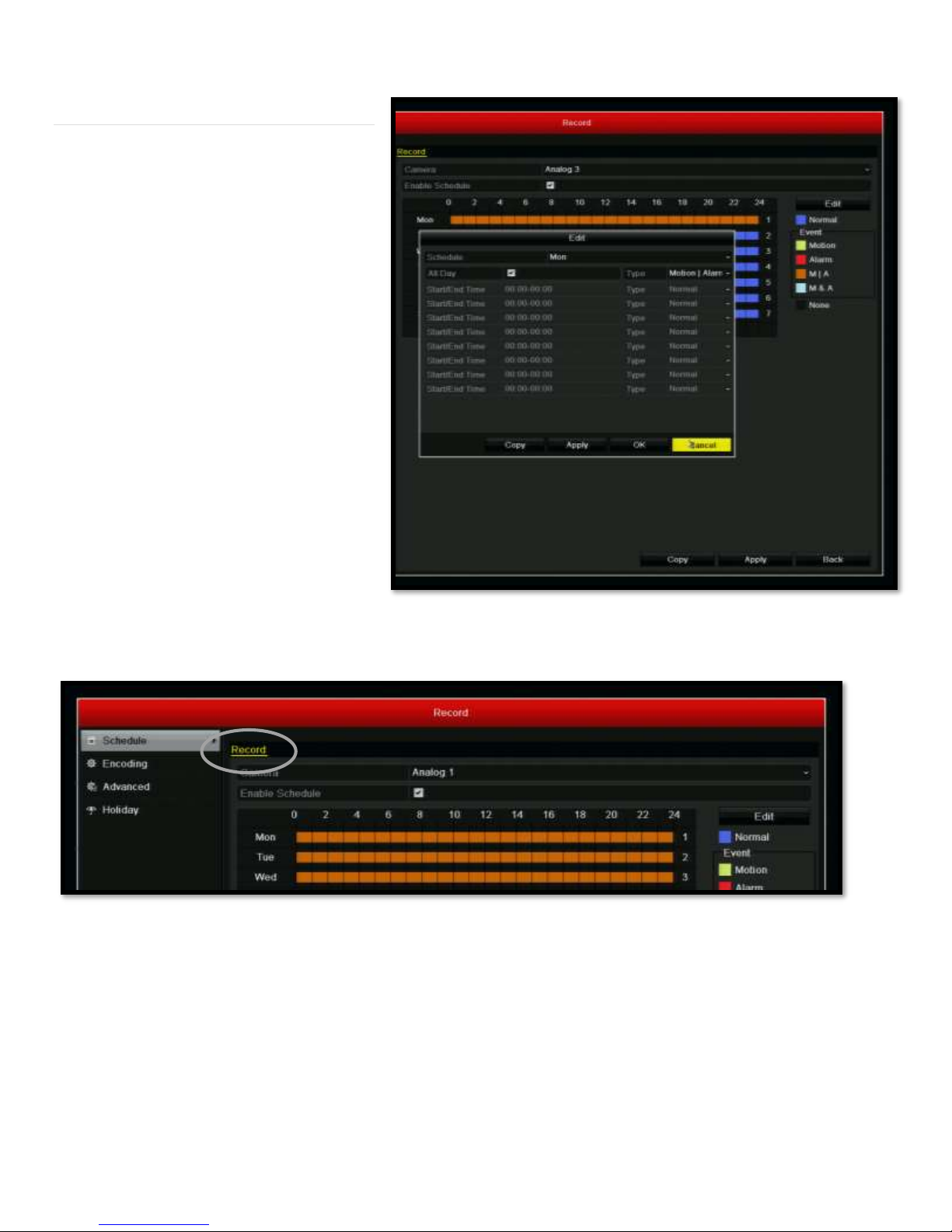
Scheduled Recording Mode
Scheduled Recording must be set for every
camera associated with verification and for
every day. The process entails first
scheduling a single camera for one day for a
24 hour period. Then, using the copy
function, this schedule can be copied to all
days and then all cameras.
To access Schedule, select the “Schedule”
option at the top left of the screen under the
“Record” menu.
Next, under the camera menu, select the first camera.
1. Enable the schedule by clicking in the box next to the “Enable Schedule”.
2. Press the “Edit” button at the right side of the screen.
3. Note that the day is Mon. This is fine for now as we will copy this to all days.
4. Check “All Day”
5. Under “Type” next to “All Day”, select “Motion|Alarm”.
Honeywell HRGX Series Installation Guide rev 2.X I-View Now, LLC. All Rights Reserved. © 2014 Page 16
Page 17
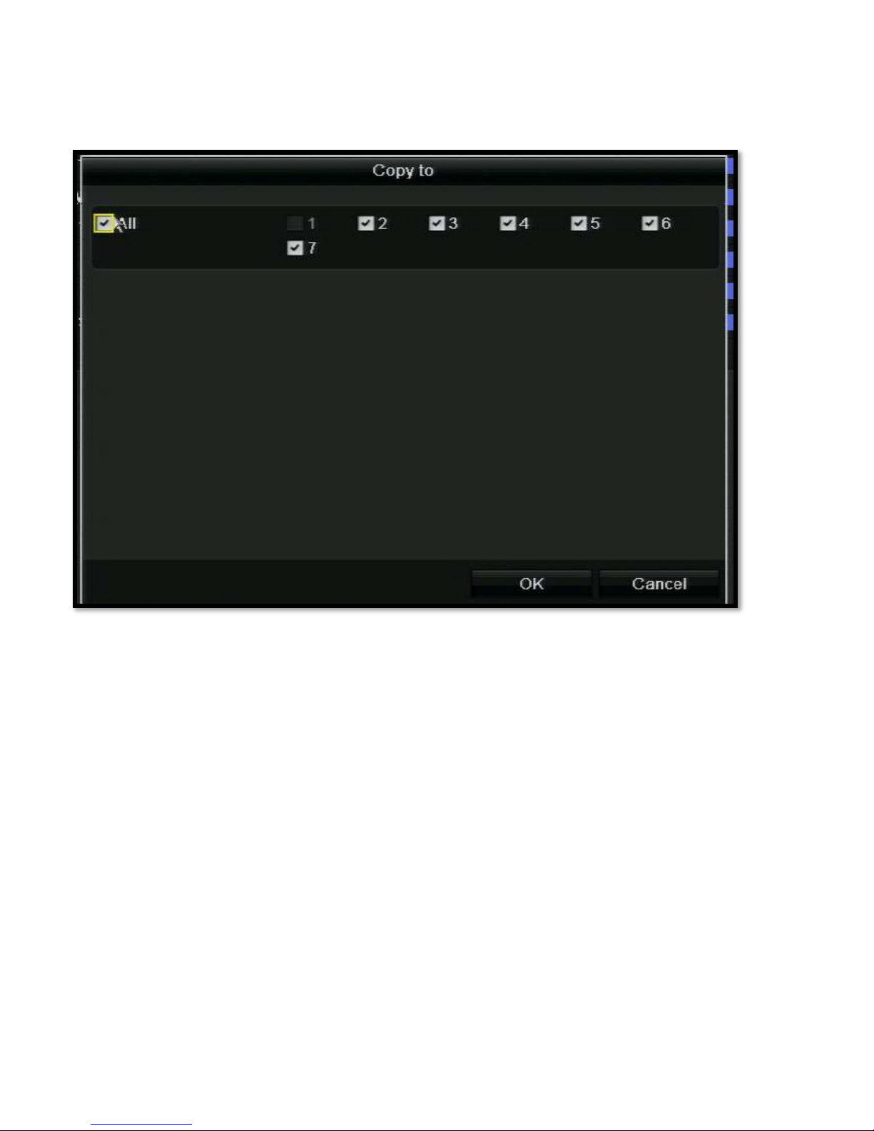
6. Click “Apply”
7. Click “Copy” and apply to all days.
8. Click “Apply” and then click “OK”.
Honeywell HRGX Series Installation Guide rev 2.X I-View Now, LLC. All Rights Reserved. © 2014 Page 17
Page 18
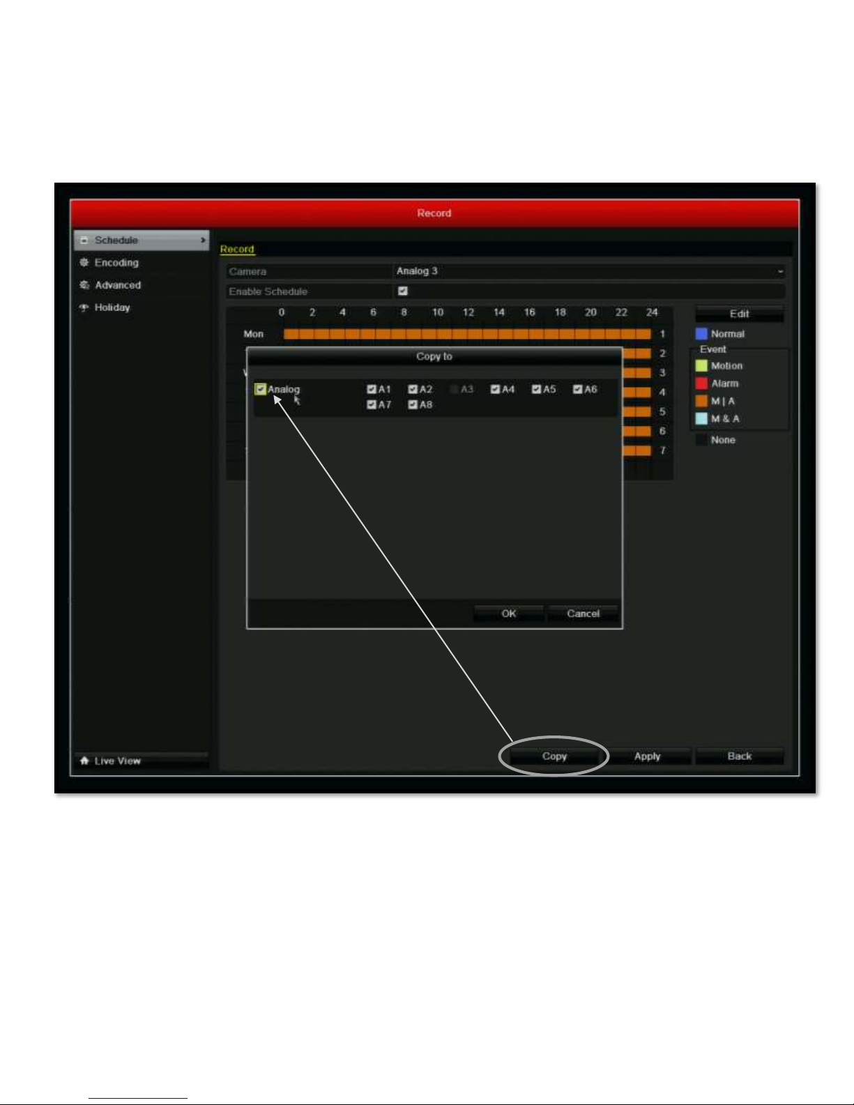
After copying the schedule to all of the days, select the “Copy” from main schedule menu to apply the schedule to all
cameras.
1. Select “Copy”
2. Select the “Analog” check box to select all cameras
3. Select “OK” in the dialog box
4. Select “Apply” from the main Schedule menu.
5. All cameras have been scheduled for all days
Honeywell HRGX Series Installation Guide rev 2.X I-View Now, LLC. All Rights Reserved. © 2014 Page 18
Page 19
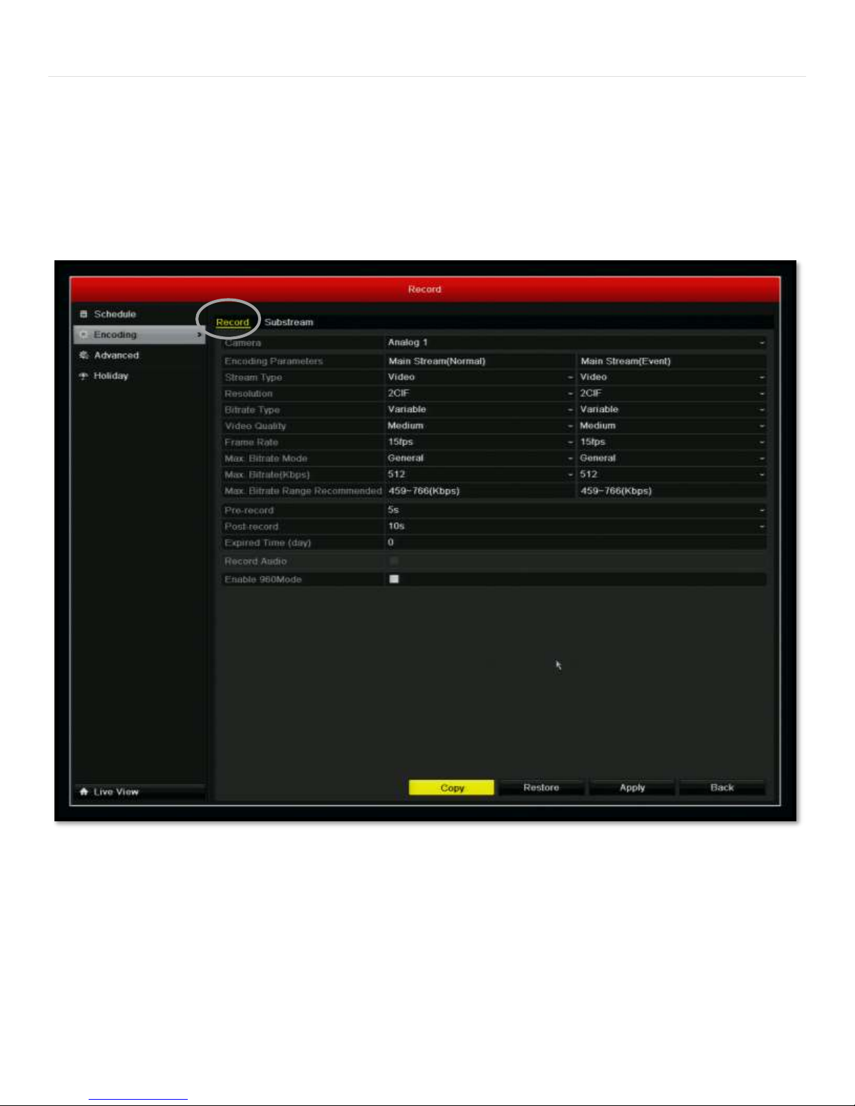
Event Recording Mode
In order to achieve the best performance from the HRGX during a video verification event, the recording parameters
must be configured. Both the “Record” menu and the “Substream” menu have parameters that need to be configured.
To locate these options, select “Record” from the main menu and then choose “Encoding” at the left.
The “Record” submenu is shown below. Note that there are two columns. One is for the Normal stream and the other is
for the event. Both columns need to be configured identically.
1. Set the Stream type to Video
2. Resolution to 2CIF
3. Bitrate Type to Variable
4. Video Quality to Medium
5. Frame Rate to 15fps
6. Max Bitrate Mode to General
7. Max Bitrate(Kbps) to 512
Honeywell HRGX Series Installation Guide rev 2.X I-View Now, LLC. All Rights Reserved. © 2014 Page 19
Page 20
8. Pre-record to 5s
9. Post record to 10s
10. Press “Apply”
11. Use the “Copy” button to copy these settings to all cameras
Be sure to make these setting changes in both columns were applicable.
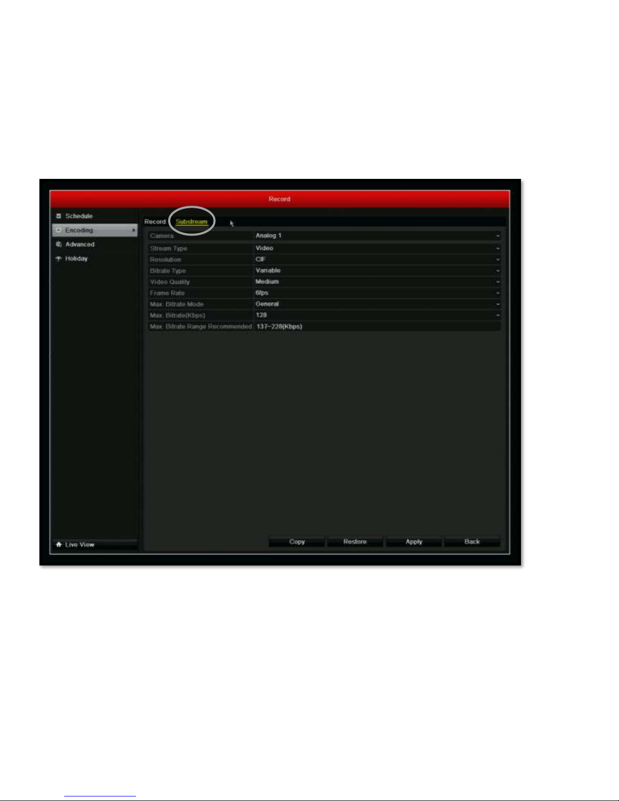
Next, the Substream needs to be configured. The substream parameters are located under the Substream submenu
within the Encoding menu.
1. Set the Stream Type to Video
2. Resolution to CIF
3. Bitrate Type to Variable
4. Video Quality to Medium
5. Frame Rate to 6fps
6. Max Bitrate Mode to General
7. Max Bitrate (Kbps) to 128 (4 & 8 channel) and 192 (16 channel).
8. Click Apply
9. Using the Copy button, copy this configuration to all cameras.
Honeywell HRGX Series Installation Guide rev 2.X I-View Now, LLC. All Rights Reserved. © 2014 Page 20
Page 21
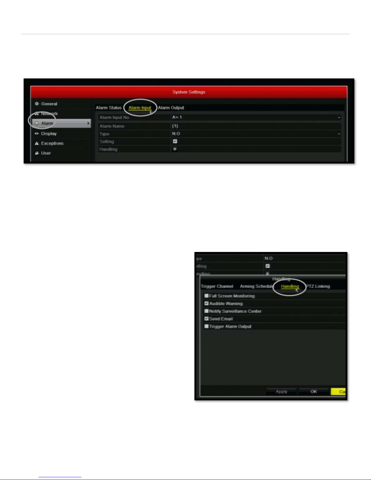
Alarm Input Setup
When an alarm is tripped, the HRGX will notify the I-View Now server. This section explains the required configuration
settings that must be made for the video verification process. Alarm input settings can be found by selecting “Settings”
from the main menu and then selecting “Alarm” from the left side menu bar.
Once on the Alarm menu, select the “Alarm Input” submenu from the top of the menu bar. The following procedure will
detail the settings for a single camera which will then be copied to all cameras by using the copy button.
1. Set the Type to N.O.
2. Place a check mark in the box next to “Setting”
3. Click on the gear symbol next to the “Handling” feature to setup how alarms are handle.
4. The “Handling” pop up menu has several submenus.
Select “Handling” which is the third menu over along
the top.
5. Check Audible Warning
6. Check Send Email
7. Click Apply
8. Click OK
Once returned back to the main Alarm Input menu, use the Copy function to copy these parameters to all cameras. The
same alarm inputs must be configured in the I-View Now Central Station Portal.
Honeywell HRGX Series Installation Guide rev 2.X I-View Now, LLC. All Rights Reserved. © 2014 Page 21
Page 22
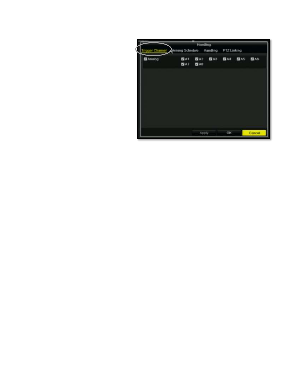
The final step is configuring the alarm inputs to select the channels that will be recorded when an alarm event occurs.
1. From the “Alarm Input” submenu, click on the
gear icon next to the “Handling” option.
“Handling” is the last row in the list of screen
options.
2. Select the “Trigger Channel” submenu
3. Select the all of the channels by clicking in the
box next to Analog
4. Click OK
Honeywell HRGX Series Installation Guide rev 2.X I-View Now, LLC. All Rights Reserved. © 2014 Page 22
Page 23
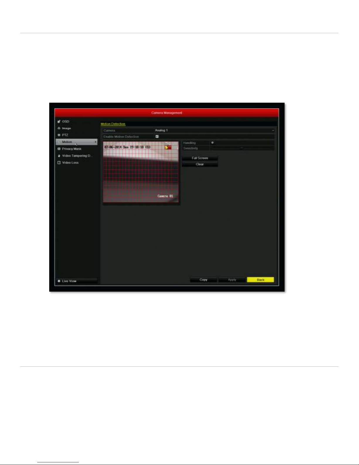
Motion Detection Setup
While not necessary for video verification or the I-View Now service, the DVR can be set to record on motion. From the
main menu, the “Motion” settings can be accessed from the main menu under the “Camera” icon. From within the
Camera menu, the Motion menu item is located on the left side menu bar. Placing a check mark in the “Enable Motion
Detection” will cause the particular camera to record on motion. The Copy button can be used to copy a single camera’s
settings to all other cameras.
Configure I-View Now Entry Delays
Entry Delays are configurable through the I-View Now Dealer Portal. Log in to configure.
Honeywell HRGX Series Installation Guide rev 2.X I-View Now, LLC. All Rights Reserved. © 2014 Page 23
Page 24

Test Settings
Once the DVR has been properly configured and the necessary settings entered into the i-viewnow.com portal, it is a
good idea to test each alarm input on the DVR by triggering the corresponding device on your alarm panel.
If relay 1, connected to input 1 on the DVR is supposed to trigger when a panic button is pushed, ensure not only that
the DVR has received the signal, but that the i-viewnow.com portal has received the signal and correctly identifies the
type of alarm.
Picture Clarity
There is an option to change the substream picture quality in either the multi-site 4200 software or the web interface to
the DVR. The substream should be set to CIF with a frame rate of 6. This will provide higher quality frames at a reduced
rate.
Honeywell HRGX Series Installation Guide rev 2.X I-View Now, LLC. All Rights Reserved. © 2014 Page 24
Page 25

Appendix A – Required Parameters
1. UPnP Enabled Router Requirement. UPnP must be enabled within the router to use the built in port forwarding
and IP address reporting capability of the device. It is import to know this before enabling the feature within the
DVR as doing so without the router being enabled will caused the installation to fail. Many routers have this
featured enabled by default, but to check, go to IPAlarmTools.com, download and run the UPnPChecker. This
must be done on the client’s network.
If UPnP is not enabled, there are two options. UPnP can be enabled within the router (which is typically a
checkbox enabling UPnP) or the traditional install method of using pre-defined IP address and ports can be used.
2. Determining the IP address. By going to IPAlarmtools.com, the external IP address will be provided.
3. Dynamic vs Static IP address – This information needs to be obtained from the site as it is a component of the
internet service’s provider agreement with the site. Another option is to go to http://whatismyipaddress.com,
enter the IP address and press “Lookup IP Address”. In the General IP Information list, there is row called
“Assignment”. The type of IP address will be listed here.
4. If the external IP is not static and assuming this is not a UPnP installation, the device will have to be configured
using a DDNS service.
5. Port Forwarding Requirements – It is necessary for I-View Now to have bi-directional communication to the
device. Some router configuration blocks communication from any port not specifically opened for
communication. From the customer’s network, go to IPAlarmtools.com and test each of the required ports
using the “Verify Port Forwarding” option. If the device requires ports 8000, 8001, and 8002, all ports should be
tested. If a port is not open and this is NOT a UPnP installation, the ports must be forwarded from within the
router. Directions for port forwarding can be found by following the link called “Port Forwarding Manuals” at
the bottom of the page on IPAlarmtools.com.
Honeywell HRGX Series Installation Guide rev 2.X I-View Now, LLC. All Rights Reserved. © 2014 Page 25
 Loading...