

Page 1
V2495
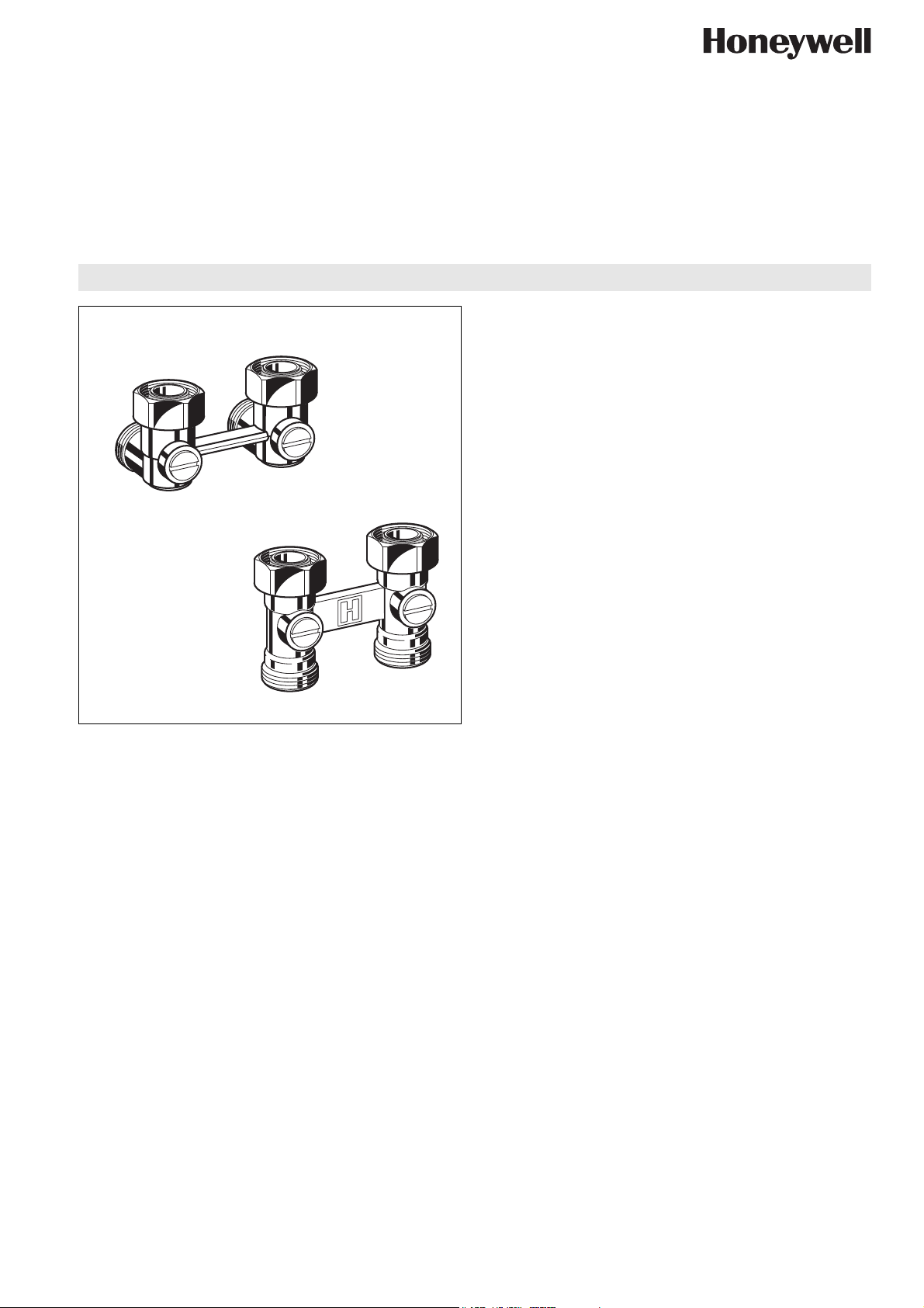
Verafix-VKE
H-BLOCK FOR COMPACT RADIATORS
PRODUCT DATA
Application
The Verafix-VKE is an lockshield valve for compact radiators
with connection centres of 50 mm. It is used on two-pipe
systems with radiators which have integral valves to regulate
and shut-off individual radiators.
Verafix-VKE is suitable for hot water heating systems.
Verafix-VKE with 1/2" internal threads are suitable for radiators
which include the following makes:
Bemm Finimètal Northor Superia
Concept Ferroli Purmo Thor
Dia-Norm Henrad Radson VEHA
Dia-therm Korado Schäfer Vogel & Noot
Dura Manaut Stelrad
Design
The Verafix-VKE consists of:
• Straight valve body for floor connection or angle valve body
for wall connection
• Ball valve insert
• Radiator connection nuts
• Universal externally threaded connections (Eurotaper
connections) suitable for copper, precision steel tube,
plastics and composite tube (see accessories for external
thread fittings)
Materials
• Hot-forged brass body
• Brass nickel ball valve insert
• EPDM O-ring sealings
• Brass union connections
• Brass radiator connection nuts
• Seat sealings PTFE
• EPDM seals
Verafix-VKE with 3/4" external threads are suitable for radiators
which include the following makes:
Baufa Buderus Kermi Ribe
Brötje De Longhi Reusch RIOPanel
Brugman
Features
• Optional flow direction. Performance values apply for
both directions of flow
• Robust brass housing
• Connection on pipework side 3/4" external thread for
copper, soft steel, plastic and composite pipes
• Connectors on radiator side 1/2" internal or 3/4" external
thread
Specifications
Medium Water
ph-value 8...9.5
Operating temperature max. 120°C (248°F)
Operating pressure max. 10.0bar (145psi)
kv(cv)-value
Straight
Angle
3.5
1.8
Honeywell y Subject to change EN0H-2211GE25 R0807
Page 2
V2495 VERAFIX-VKE
Function
The supply and return of the radiator can be shut-off by turning the ball valve inserts of the Verafix-VKE to the horizontal position
with a screwdriver. The valves are supplied set fully open.
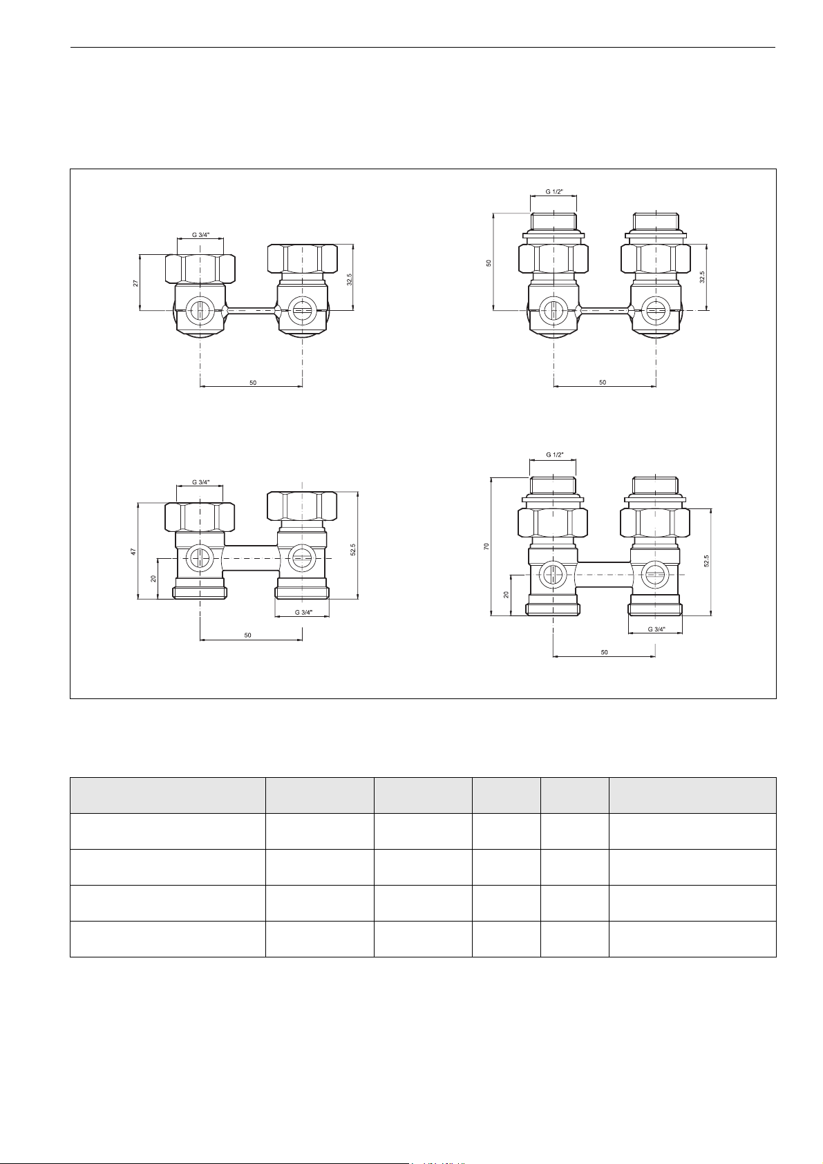
Dimensions
Fig. 1. Dimensions Verafix-VKE angle
with integrated cone
Fig. 3. Dimensions Verafix-VKE straight
with integrated cone
NOTE: All dimensions in mm unless stated otherwise.
Ordering Information
Table. 1. Dimensions and OS-Nos (OS=Ordering System)
Type Pipe connection Radiator
connection
Angle (wall connection) integrated
cone
Angle (wall connection) integrated
cone and double nippel
Straight (floor connection)
integrated cone
Straight (floor connection) inte-
grated cone and double nippel
3
/4” external
3
/4” external
3
/4” external
3
/4” external
3
/4” external 15 1.8 V2495EX020A
1
/2” internal 15 1.8 V2495EY015A
3
/4” external 15 3.5 V2495DX020
1
/2” internal 15 3.5 V2495DY015
Fig. 2. Dimensions Verafix-VKE angle
with integrated cone and double nippel
Fig. 4. Dimensions Verafix-VKE straight
with integrated cone and double nippel
DN kvs(cv)-
OS-No.
value
Honeywell y Subject to change 2 EN0H-2211GE25 R0807
Page 3

V2495 VERAFIX-VKE
Accessories
Connections for copper and soft steel pipe (2 pcs.)
3/4" x 10 mm VA7200A010
3/4" x 12 mm VA7200A012
3/4" x 14 mm VA7200A014
3/4" x 15 mm VA7200A015
3/4" x 16 mm VA7200A016
3/4" x 18 mm VA7200A018
Connection for PE-X pipe (2 pcs.)
3/4" x 14 x 2 mm OT112M-3/4D
3/4" x 16 x 2 mm OT112M-3/4F
3/4" x 16 x 2,2 mm OT112M-3/4F2
3/4" x 17 x 2 mm OT112M-3/4G
3/4" x 18 x 2 mm OT112M-3/4H
Connection for composite pipe (2 pcs.)
3/4" x 14 x 2 mm OT113M-3/4D
3/4" x 16 x 2 mm OT113M-3/4F
3/4" x 18 x 2 mm OT113M-3/4H
Connection for copper pipe (2 pcs.)
3/4" x 10 mm OT114M-3/4B
3/4" x 12 mm OT114M-3/4C
3/4" x 14 mm OT114M-3/4D
3/4" x 15 mm OT114M-3/4E
3/4" x 16 mm OT114M-3/4F
3/4" x 18 mm OT114M-3/4H
Double nippel (2 pcs.)
for all V2495 VS3295A015
Installation Example
Fig. 5. Two-pipe system with distribution manifold and Verafix-VKE
Please Note:
• To avoid stone deposit and corrosion the composition of the
medium should conform with VDI-Guideline 2035
• Additives have to be suitable for EPDM sealings
• System has to be flushed thoroughly before initial operation
with all valves fully open
• Any complaints or costs resulting from non-compliance with
above rules will not be accepted by Honeywell
• Please contact us if you should have any special requirements or needs
Honeywell y Subject to change 3 EN0H-2211GE25 R0807
Page 4

V2495 VERAFIX-VKE
Flow Diagram VKE2495E
2
1.6
1.2
P (bar )
0.8
∆
0.4
0
5 101520 2530 3540
lt./min5 10152025303540
∆p (bar)0.010.070.200.390.631.001.451.92
lt./m in
Flow Diagram VKE2495D
1
0.9
0.8
0.7
0.6
0.5
0.4
P (bar )
∆
0.3
0.2
0.1
0
20 25 30 35 40 45 50 6055
lt./min202530354045505560
∆p (bar)0.070.130.200.29 0.38 0.50 0.62 0.76 0.91
lt./m in
Automation and Control Solutions
Honeywell GmbH
Hardhofweg
74821 Mosbach, Germany
Phone: +49 (6261) 810
Fax: +49 (6261) 81393
www.honeywell.com
EN0H-2211GE25 R0807
August 2007
© 2007 Honeywell International Inc.
Subject to change without notice
Manufactured for and on behalf of the Environmental and Combustion
Controls Division of Honeywell Technologies Sàrl, Ecublens, Route
du Bois 37, Switzerland or its authorized representative.
 Loading...