

Page 1
V2465, V2466
Verafix-EK
LOCKSHIELD VALVES FOR COMPACT RADIATORS
PRODUCT DATA
Application
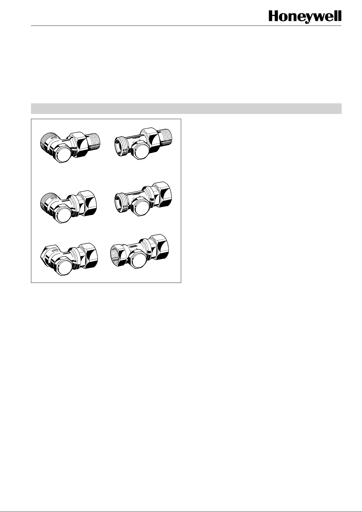
The Verafix-EK is a single lockshield valve to connect compact radiators or universal radiators to heating loops of twopipe heating systems. It offers shutoff, presetting, draining
and filling function. Two Verafix-EK are required to connect a
radiator to the heating circuit.
Features
• Offers shutoff, pre-setting, draining and filling function
• Draining and filling by means of draining adapter with
3/4" hose connection (accessory)
• Optional flow direction
• Valve body made of corrosion-resistant red bronze
• Available for various types of pipe and radiator con-
nections
Design
The Verafix-EK is made up of:
•
Valve housing PN10, DN15, valve inlet with external
threads 3/4" Eurocone for connection of copper, soft steel
or composite pipe using connection fittings (see ‘Accessories’ on page 3). Or with internal threads according to
ISO 7 (DIN 2999) for direct connection of threaded pipe or
connection of copper, soft steel or composite pipe using
compression fittings (see ‘Accessories’)
•
Valve insert
•
Cap
•
Union-nut, partly with tailpiece. Suitable for radiators with
G 3/4” external threads or R 1/2” internal threads
Materials
•
Valve housing made of nickel-plated red bronze RG5
according to DIN 1705
•
Valve insert made of brass with EPDM O-rings
•
Cap made of brass with PTFE sealing
•
Union-nut and tailpiece made of brass, union-nut addition-
nally nickel-plated
Specifications
Medium
pH-value
Operating temperature
Operating pressure
vs
-values
k
Heating water
8...9,5
max. 130°C (266°F)
max. 10 bar (145 P.S.I.)
1,70 (angle body)
1,45 (straight body)
Function
The flow rate through the Verafix-EK is throttled to the desired value by pre-setting the valve insert with a 4 mm Allan
key. Relation between number of turns and flow rate can be
taken from the flow diagram at the end of this data sheet.
Pre-setting only has to be done on one valve. The Verafix-EK
doesn’t need to be pre-set when the radiator is equipped with
a pre-settable TRV insert and throttling is done over that
device.
The radiator is shutoff from the heating circuit by turning the
valve inserts of both Verafix-EK clockwise as far as possible.
The radiator can be drained and filled over the Verafix-EK by
using the draining adapter (accessory).
Verafix-EK lockshield valves are supplied fully open.
Copyright © 2001 Honeywell AG • All rights reserved EN0H-189GE25 R0101
Page 2
VERAFIX-EK
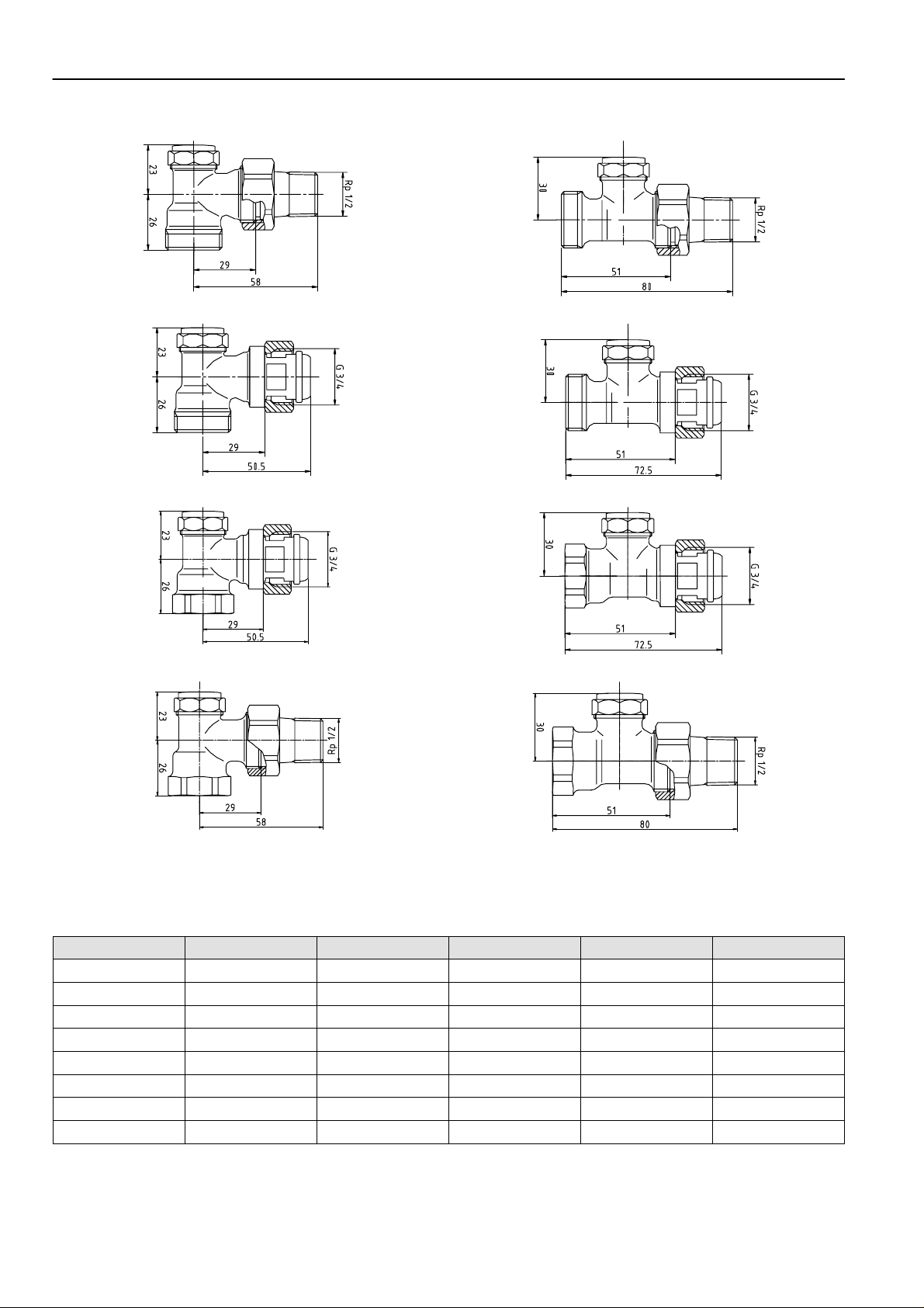
Dimensions
Fig. 1. Angle with 3/4“ external to 1/2“ external thread Fig. 2. Straight with 3/4“ external to 1/2“ external thread
Fig. 3. Angle with 3/4“ external to 3/4“ internal thread Fig. 4. Straight with 3/4“ external to 3/4“ internal thread
Fig. 5. Angle with 1/2“ internal to 3/4“ internal thread Fig. 6. Straight with 1/2“ internal to 3/4“ internal thread
Fig. 7. Angle with 1/2“ internal to 1/2“ external thread Fig. 8. Straight with 1/2“ internal to 1/2“ external thread
NOTE: All dimensions given in mm unless otherwise stated.
Ordering Information
Type DN Valve inlet Valve outlet kvs-value OS-No.
Angle 15 3/4" external 1/2" external 1,70 V2465EY015
Straight 15 3/4" external 1/2" external 1,45 V2465DY015
Angle 15 3/4" external 3/4" internal 1,70 V2465EX020
Straight 15 3/4" external 3/4" internal 1,45 V2465DX020
Angle 15 1/2" inter nal 3/4" internal 1,70 V2466EX020
Straight 15 1/2" internal 3/4" internal 1,45 V2466DX020
Angle 15 1/2" inter nal 1/2" external 1,70 V2420E0015
Straight 15 1/2" internal 1/2" external 1,45 V2420D0015
EN0H-189GE25 R0101 2 Honeywell AG • All rights reserved
Page 3

Accessories
Draining adapter
for all Verafix-EK 0 08 08 02 000 000
VERAFIX-EK
External thread fittings for composite pipe (2 pcs)
3/4" x 14 x 2 mm 1 01 01 46 240 000
3/4" x 16 x 2 mm 1 01 01 46 260 000
3/4" x 18 x 2 mm 1 01 01 46 280 000
Special Verafix-key
for all Verafix-EK 0 44 20 00 110 000
Compression fitting for copper and soft steel pipe
1/2" x 10 mm 1 01 01 37 015 000
1/2" x 12 mm 1 01 01 15 015 000
1/2" x 14 mm 1 01 01 19 015 000
1/2" x 15 mm 1 01 01 22 015 000
1/2" x 16 mm 1 01 01 21 015 000
NOTE: Use support inserts for soft steel and copper pipe
(wall thickness 1,0 mm, also see DVGW-Guideline
GW 2).
Compression fitting with support inserts for copper and soft steel
pipe (2 pcs)
1/2" x 12 mm 1 01 01 38 120 000
1/2" x 15 mm 1 01 01 38 150 000
1/2" x 16 mm 1 01 01 38 160 000
External thread fittings for copper and soft steel pi pe (2 pcs)
3/4" x 10 mm 1 01 01 47 100 000
3/4" x 12 mm 1 01 01 47 120 000
3/4" x 14 mm 1 01 01 47 140 000
3/4" x 15 mm 1 01 01 47 150 000
3/4" x 16 mm 1 01 01 47 160 000
3/4" x 18 mm 1 01 01 47 180 000
Radiator tailpiece with thread up to collar
for all Verafix-EK 0 20 17 01 015 801
Extension tailpiece
for all Verafix-EK 0 20 17 03 015 000
Soldering tailpiece
for all Verafix-EK 0 20 53 01 015 000
Nickel-plated union-nut
for all Verafix-EK 0 20 18 15 015 926
Nickel-plated cap
for all Verafix-EK 0 20 55 04 240 926
Sealing for cap
for all Verafix-EK 0 40 45 10 210 000
External thread fittings for plastic pipe (2 pcs)
3/4" x 12 x 2 mm 1 01 01 46 120 000
3/4" x 14 x 2 mm 1 01 01 46 140 000
3/4" x 16 x 2 mm 1 01 01 46 160 000
3/4" x 17 x 2 mm 1 01 01 46 170 000
3/4" x 18 x 2 mm 1 01 01 46 180 000
Honeywell AG • All rights reserved 3 EN0H-189GE25 R0101
Page 4

VERAFIX-EK
Flow Diagram
Pre-setting =
Number of turns
kv-value angle
kv-value straight
Home and Buil ding Control
Honeywell AG Phone: (49) 2932 9880
Zu den Ruhrwiesen 3 Fax: (49) 2932 988239
D-59755 Arnsberg-Neheim mng@honeywell.com http://europe.hbc.honeywell.com
EN0H-189GE25 R0101 4 Subject to change • All rights reserved
1/4 1/2 1 1 1/2 2 2 1/2 3 4 = open
0,13 0,22 0,43 0,65 0,85 1,10 1,25 kvs = 1,70
0,13 0,22 0,43 0,65 0,85 1,10 1,25 kvs = 1,45
 Loading...