

Page 1
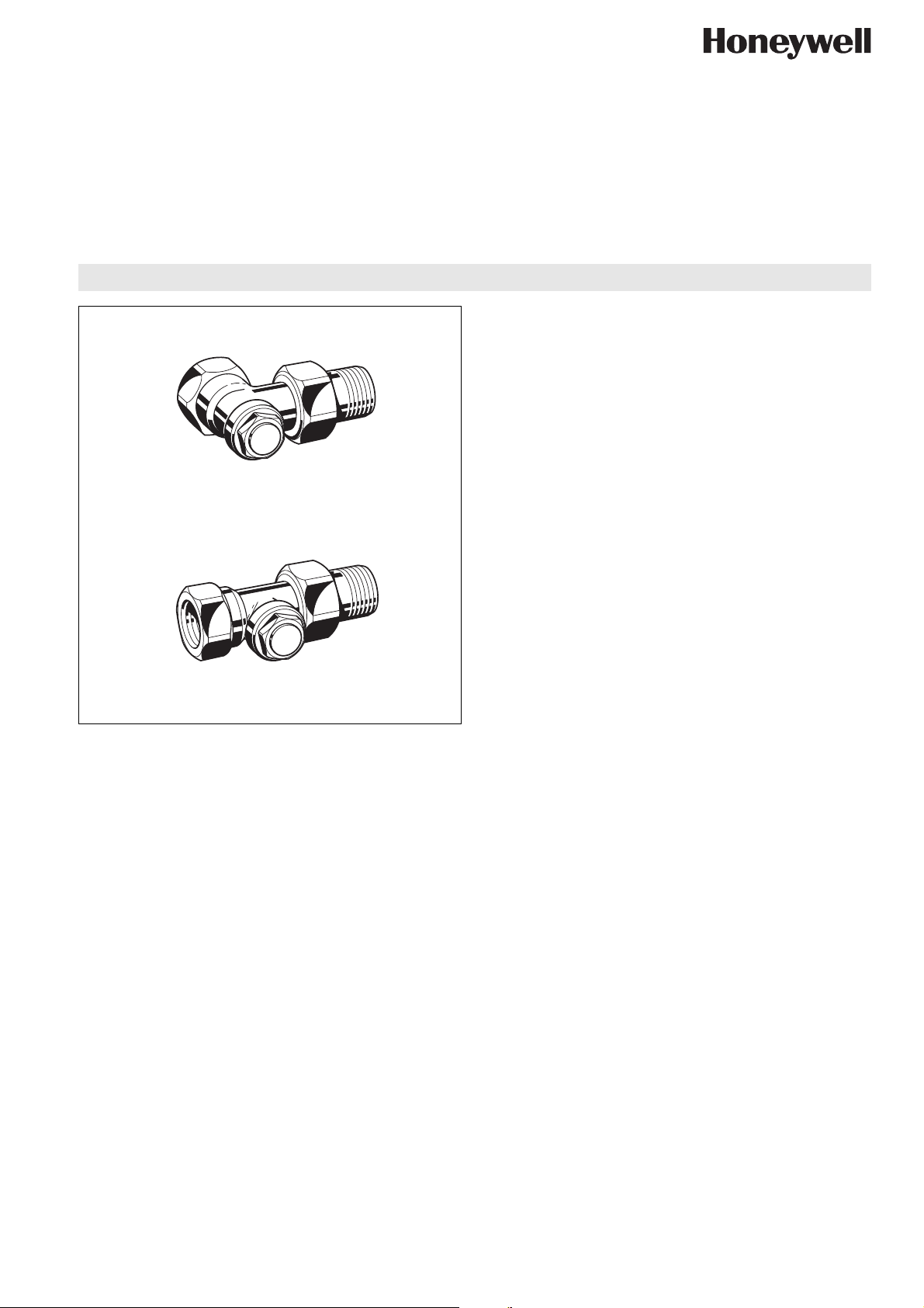
LOCKSHIELD VALVE WITH MEASURING FACILITY
1/2
Angle
1/2
Straight
Design
The lockshield valve consists of:
• Valve housing PN10, DN10, 15 or 20 with
• internal thread connection to DIN2999 (ISO7) or external
thread connection to DIN/ISO228 on inlet
• external thread connection to DIN/ISO228 with union-nut
and radiator tailpiece (not V2406) on outlet
• Body dimensions to DIN3842
• Valve insert
• Protection cap
V2410
Verafix-MES-II
PRODUCT DATA
Application
The Verafix-MES-II is a radiator lockshield valve with
measuring support for the supply or return of radiators or heat
exchangers. It is used for measuring, shutoff and draining/filling
of individual radiators in two-pipe heating systems. In combination with a pre-settable TRV body the Honeywell measuring
method can be applied: measuring and pre-setting at the same
time.
The Verafix-MES-II is suitable for hot water heating systems
and cold water cooling systems.
Features
• Measuring and pre-setting at the same time
• Measuring, shutoff and draining/filling with one valve
• Optional flow direction. Performance values apply for
both directions
• Piston externally O-ring sealed
• Body dimensions to DIN3842
• Robust corrosion-resistant red bronze housing
• Connection to all types of pipe DN10...DN20
• Easy identification: cover cap with hexagon and raised
circular centre; also see illustrations identification
Specifications
Medium Water, water-glycol mixture
Quality to VDI2035
Operating temperature 2...130°C (36...266°F)
Operating pressure PN 10
k
(cv)-values Angle 1.0 (1.17)
vs
Straight DN10 0.8 (0.94)
Straight DN15 0.9 (1.05)
Straight DN20 1.0 (1.17)
Materials
• Valve housing made of nickel-plated red bronze
• Valve insert made of brass with EPDM seals
• Tailpiece, protection cap and union-nut made of nickelplated brass
Honeywell y Subject to change EN0H-2201GE25 R1106
Page 2
V2410 - VERAFIX-MES-II
Function
The Verafix-MES-II connects the return of a radiator or heat
exchanger to the water loop and has the functions measuring,
shutoff and draining/filling.
Measuring:
To measure the flow the VA3301A measuring adapter is
connected to the Verafix-MES-II and a measuring device, for
example BasicMES is connected to the measuring adapter.
Pre-setting of the required flow rate is done using the Honeywell measuring method: the water quantity is measured and is
then adjusted as required on the pre-settable V, FV or SC type
TRV. Closing or opening of the TRV is immediately indicated
on the measuring device as a lower or higher flow rate.
The Verafix-MES-II has two fixed kv-values: measuring
range II (standard) and measuring range I for low flow rates.
The valve is supplied set to measuring range II.
For correct measurements the right measuring range or kvvalue has to be fed into the measuring device.
Also see chapter ‘Flow Diagram’.
NOTE: Measuring and pre-setting at the same time can only
be done when a pre-settable TRV body is installed,
e.g. Honeywell VS, FS, FV or SC type.
Shutoff:
The return of the radiator can be shutof f by clo si n g the valve
insert.
Draining:
Draining or filling of the radiator is carried out with the draining
adapter (see ‘Accessories’). Draining of individual radiators
using the Verafix-MES-II has no influence on the heating loop
or other radiators in the loop.
Detailed illustrations of above functions see chapter Shutoff/
Draining and Change to Measuring Range I
Please Note:
• To avoid stone deposit and corrosion the composition of the
medium should conform with VDI-Guideline 2035
• Additives have to be suitable for EPDM sealings
• System has to be flushed thoroughly before initial operation
with all valves fully open
• Any complaints or costs resulting from non-compliance with
above rules will not be accepted by Honeywell
• Please contact us if you should have any special requirements or needs
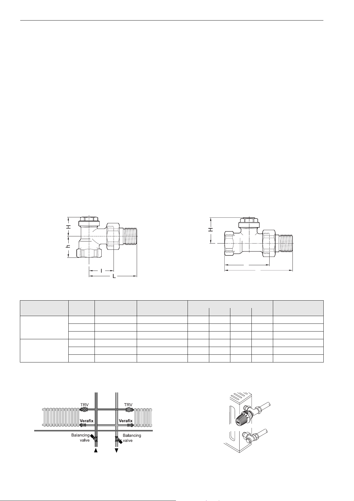
Dimensions and Ordering Information
l
L
Fig. 1. Angle Fig. 2. Straight
T able 1. Dimensions and OS-Nos (OS=Ordering System)
Type
Angle (Fig. 1) 10 Rp 3/8" 0.2/1.0(0.23/1.17) 52 26 25 22 V2410E0010
Straight (Fig. 2) 10 Rp 3/8" 0.2/0.8 (0.23/0.94) 75 49 32 — V2410D0010
NOTE: All dimensions in mm unless stated otherwise.
DN
15 Rp
20 Rp
15 Rp
20 Rp
Pipe connec-
tion
1
/2" 0.2/1.0(0.23/1.17) 58 29 25 26 V2410E0015
3
/4" 0.2/1.0(0.23/1.17) 66 34 29 29 V2410E0020
1
/2" 0.2/0.9 (0.23/1.05) 80 51 32 — V2410D0015
3
/4" 0.2/1.0(0.23/1.17) 91 59 32 — V2410D0020
kvs(cv)-value
Dimensions in mm
L I H h
OS-No.
Installation Examples
Fig. 3. Installation example heating system Fig. 4. Installation example radiator
EN0H-2201GE25 R1106 2 Honeywell y Subject to change
Page 3

Accessories
Connections for V2410 Valve Accessories
Compression ring and nut
3/8" x 10 mm VA620A1010
3/8" x 12 mm VA620A1012
1/2" x 10 mm VA620A1510
1/2" x 12 mm VA620A1512
1/2" x 14 mm VA620A1514
1/2" x 15 mm VA620A1515
1/2" x 16 mm VA620A1516
3/4" x 18 mm VA620A2018
3/4" x 22 mm VA620A2022
NOTE: Support inserts have to be used for copper or soft
steel pipe with 1.0 mm wall thickness
Compression ring and nut with support insert (2 pcs each)
3/8" x 12 mm VA621A1012
1/2" x 12 mm VA621A1512
1/2" x 15 mm VA621A1515
1/2" x 16 mm VA621A1516
3/4" x 18 mm VA621A2018
Compression ring and nut with support insert for composite pipe (2 pcs each)
1/2" x 14 mm VA622B1514
1/2" x 16 mm VA622B1516
Radiator tailpiece with thread up to collar
for valves DN10 (3/8") VA5201A010
for valves DN15 (1/2") VA5201A015
for valves DN20 (3/4") VA5201A020
Extended radiator tailpiece, nickel-plated, to be shortened
as required
3/8" x 70 mm (for DN10)
thread approx. 50 mm
1/2" x 76 mm (for DN15)
thread approx. 65 mm
3/4" x 70 mm (for DN20)
thread approx. 60 mm
Soldering tailpiece
3/8" x 12 mm (for DN10) VA5230A010
1/2" x 15 mm (for DN15) VA5230A015
3/4" x 22 mm (for DN20) VA5230A020
VA5204A010
VA5204A015
VA5204A020
Draining adapter
for all sizes VA3300A001
Verafix key
for all sizes VA8300A001
Measuring adapter
for all sizes VA3301A001
VM200 Flow Meter
for Verafix-MES and
Kombi-3-Plus
VM241 BasicMes handheld measuring computer
computer is supplied with
case and accessories
Service Parts
Cover cap
for all sizes VS3301B001
Sealing ring for cover cap
for all sizes VS3302A001
Exchange valve insert
V2410 - VERAFIX-MES-II
VM200A1001
VM241A1002
VS1300VM01
Pressure cap – for shutting off valves on radiator outlet
for valves DN10 (3/8") VA2202A010
for valves DN15 (1/2") VA2202A015
for valves DN20 (3/4") VA2202A020
Sealing ring for pressure cap
for valves DN10 (3/8") VA5090A010
for valves DN15 (1/2") VA5090A015
for valves DN20 (3/4") VA5090A020
Honeywell y Subject to change 3 EN0H-2201GE25 R1106
Page 4

V2410 - VERAFIX-MES-II
Identification
Protection cap fitted: protection
cap with hexagon (SW19), raised
circular centre on top and collar
on valve side
Protection cap removed:
valve in-sert with ribbed rim
and two inside hexagons
(SW10 and SW4)
Fig. 5. Identification of Verafix-MES-II
EN0H-2201GE25 R1106 4 Honeywell y Subject to change
Page 5

Flow Diagram
V2410 - VERAFIX-MES-II
Flow values (cv-values in brackets)
Nominal size diameter DN 10 DN 15 DN 20
Measuring range I II I II I II
Angle (Fig. 1) 0.2 (0.23) 1.0 (1.17) 0.2 (0.23) 1.0 (1.17) 0.2 (0.23) 1.0 (1.17)
Straight (Fig. 2) 0.2 (0.23) 0.8 (0.94) 0.2 (0.23) 0.9 (1.05) 0.2 (0.23) 1.0 (1.17)
Honeywell y Subject to change 5 EN0H-2201GE25 R1106
Page 6

V2410 - VERAFIX-MES-II
Automation and Control Solutions
Honeywell GmbH
Hardhofweg
74821 Mosbach, Germany
Phone: +49 (6261) 810
Fax: +49 (6261) 81393
www.honeywell.com
EN0H-2201GE25 R1106
November 2006
© 2006 Honeywell International Inc.
Subject to change • All rights reserved
Manufactured for and on behalf of the Enviro nmental and Combustion
Controls Division of Honeywell Technologies Sàrl, Ecublens,
Route du Bois 37, Switzerland or by its Authorized Representative.
 Loading...