

Honeywell TCONT802AS32DA Owner's Manual
INSTALLATION INSTRUCTIONS
69-1790-3
U.S. Pat. No. 6595430, D509151, and Other Patents Pending
TCONT802AS32DA Touch Screen and
TCONT803AS32DA Touch Screen with
Dehumidification Control Comfort Controls
18-HD25D19-3
APPLICATION
The TCONT802AS32DA and TCONT803AS32DA Touch Screen Comfort Controls provide electronic control of 24 Vac
heating and cooling systems. See Table 1 for a general description.
MERCURY NOTICE
If this control is replacing a control that contains
mercury in a sealed tube, do not place your old
control in the trash. Dispose of properly.
Contact your local waste management authority
for instructions regarding recycling and the
proper disposal of the old control.
INSTALLATION
When Installing this Product...
1. Read these instructions carefully. Failure to follow
the instructions can damage the product or cause
a hazardous condition.
2. Installer must be a trained, experienced service
technician.
3. After completing installation, use these instructions
to check out the product operation.
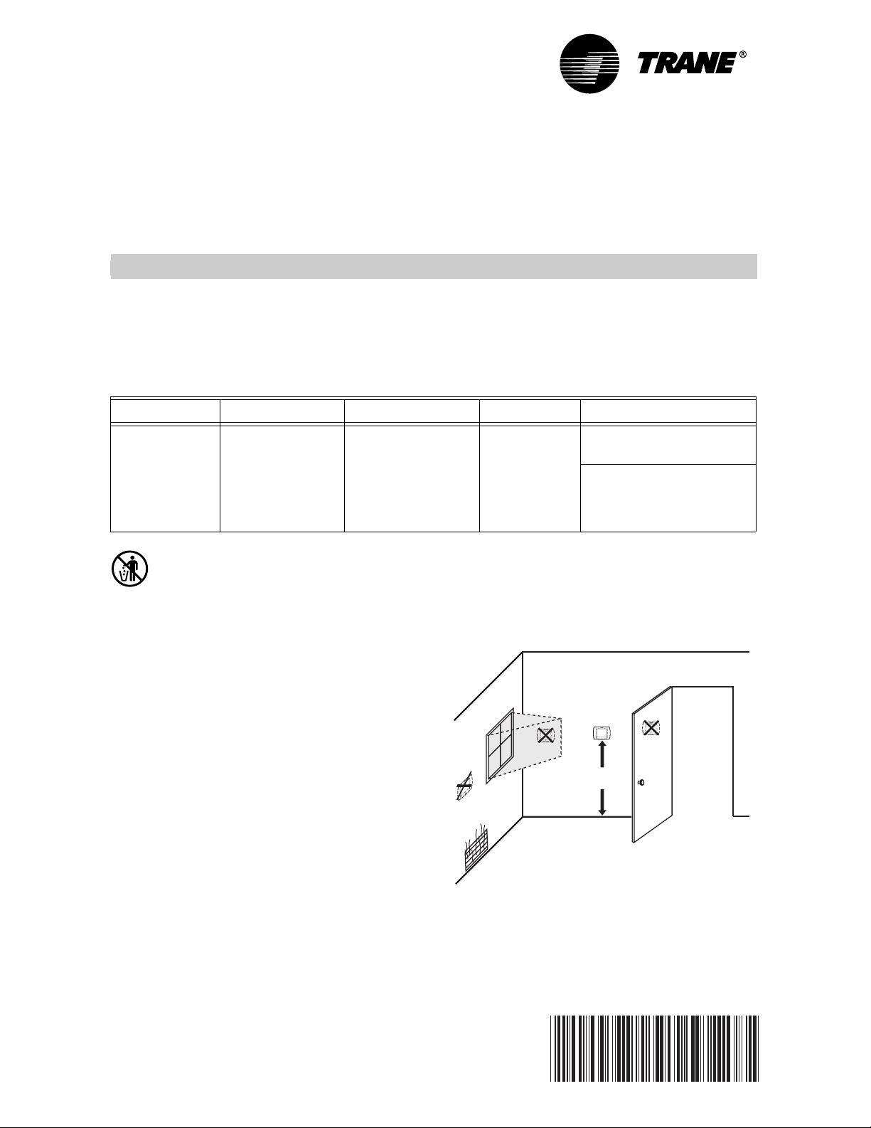
Selecting Location
Install the comfort control about 5 ft. (1.5m) above the
floor in an area with good air circulation at average
temperature. See Fig. 1.
Fig. 1. Selecting comfort control location.
Table 1. TCONT802AS32DA and TCONT803AS32DA Comfort Control Description.
Power Method Changeover System Selection Fan Selection Comments
24 Vac common
wire
Automatic or
manual selectable
Heat-Off-CoolAuto (Em. Heat
for heat pumps)
On-Auto-Circ System and Fan selection
vary based on system type
System and Fan selection
vary based on System type.
Humidity sensor to control
dehumidification.
5 FEET
[1.5 METERS]
YES
NO
NO
NO
M19925
TCONT802AS32DA TOUCH SCREEN AND TCONT803AS32DA TOUCH SCREEN WITH DEHUMIDIFICATION
Pub. No. 18-HD25D19-3
69-1790—3 2
Do not install the comfort control where it can be affected
by:
— Drafts or dead spots behind doors and in corners.
— Hot or cold air from ducts.
— Radiant heat from sun or appliances.
— Concealed pipes and chimneys.
— Unheated (uncooled) areas such as an outside wall
behind the comfort control.
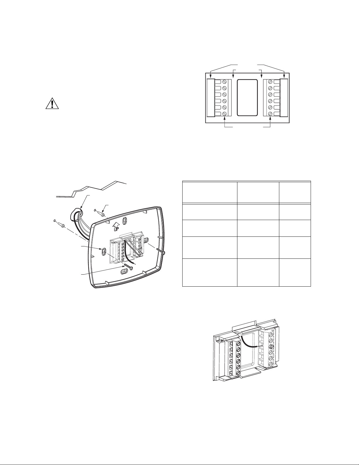
Installing Wallplate
CAUTION
Electrical Hazard.
Can cause electrical shock or equipment
damage.
Disconnect power before wiring.
The comfort control can be mounted horizontally on the
wall or on a 4 in. x 2 in. (101.6 mm x 50.8 mm) wiring box.
1. Position and level the wallplate (for appearance
only).
2. Use a pencil to mark the mounting holes.
Fig. 2. Mounting wallplate.
3. Remove the wallplate from the wall and, if drywall,
drill two 3/16-in. holes in the wall, as marked. For
firmer material such as plaster, drill two 7/32-in.
holes. Gently tap anchors (provided) into the drilled
holes until flush with the wall.
4. Position the wallplate over the holes, pulling wires
through the wiring opening. See Fig. 2.
5. Insert mounting screws into the holes and tighten.
WIRING (FIG. 5-15)
All wiring must comply with local electrical codes and
ordinances.
1. Select set of terminal identifications (Table 2) that
corresponds with system type (heat/cool or heat
pump in Fig. 3).
2. Loosen the screws for the appropriate system type
selected; see Table 2. Insert wires in the terminal
block under the loosened screw. See Fig. 4.
3. Securely tighten each screw.
4. Push excess wire back into the hole.
5. Plug the hole with nonflammable insulation to pre-
vent drafts from affecting the comfort control.
Fig. 3. Selecting terminal identifications for
system type.
NOTE: The factory default setting is configured for a
1 Heat/1 Cool System with a gas furnace.
Fig. 4. Inserting wires in terminal block.
IMPORTANT
Use 18 gauge comfort control wire.
WALL
MOUNTING
HOLES
M19916
MOUNTING
SCREWS (2)
WALL ANCHORS (2)
WIRES THROUGH WALL
AND WIRE SLOT
Table 2. Selecting Terminal Identifications for
System Type.
System Type
Wallplate
Termi nal
Identifications
Wiring
Diagram
Reference
Standard Heat/Cool Heat/Cool Fig. 5,
Fig. 6
Standard Multistage
up to 2 Heat/2 Cool
Heat/Cool Fig. 7,
Fig. 8
Heat Pump with
Electric Auxiliary
(Backup) Heat
Heat Pump Fig. 9,
Fig. 10,
Fig. 11
Heat Pump with
Fossil Fuel Auxiliary
(Dual Fuel) Heat
Heat Pump Fig. 12,
Fig. 13,
Fig. 14,
Fig. 15
HEAT
/COOL
SC
REW TERMINAL
S
HEAT PUM
P
M22636
Y2
F
X2
W1
S1
S2
W2
S1
S2
RC
R
O
Y
G
B
R
C
W1
Y
G
M19917
TCONT802AS32DA TOUCH SCREEN AND TCONT803AS32DA TOUCH SCREEN WITH DEHUMIDIFICATION
Pub. No. 18-HD25D19-3
3 69-1790—3
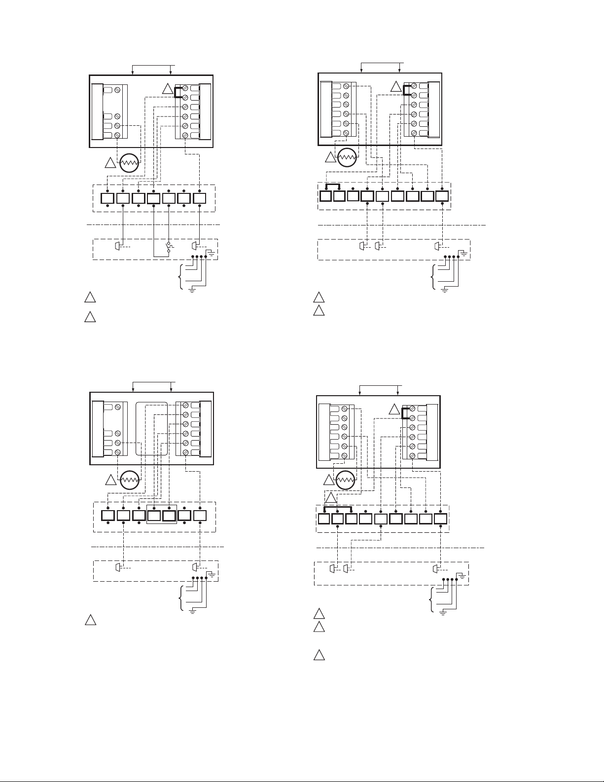
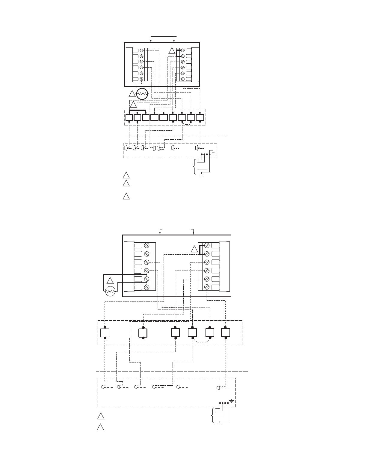
Fig. 5. Typical hookup of single-stage heat and cool
system with single transformer (1H/1C).
Fig. 6. Typical hookup of single-stage heat and cool
system with two transformers (1H/1C).
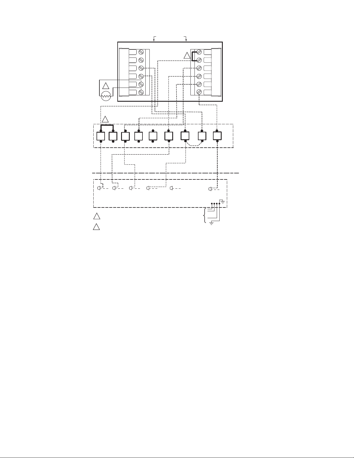
Fig. 7. Typical hookup of two-stage indoor and
two-stage cooling unit in a single transformer system
(2H/2C or 2H/1C or 1H/2C).
Fig. 8. Typical hookup of two-stage indoor and
two-step scroll cooling unit in a single transformer
system (2H/2C or 2H/1C or 1H/2C).
1
M22637
FACTORY INSTALLED JUMPER.
OPTIONAL OUTDOOR OR INDOOR REMOTE SENSOR. AVAILABLE
ON SELECT MODELS. WIRES MUST HAVE A CABLE SEPARATE
FROM THE THERMOSTAT CABLE.
1
2
2
RC
S1
R
S2
W1
Y
G
B
HEAT/COOL
T
B/C
W3
W2
W1
GYR
AIR
HANDLER
Y
B
COOLING UNIT
O.D. SECTION
(SINGLE STAGE)
TO POWER SUPPLY
PER LOCAL CODES
(3 PH
ONLY)
INDOOR
OUTDOOR
ODT
Y2
W2
OPTIONAL OUTDOOR OR INDOOR REMOTE SENSOR. AVAILABLE
ON SELECT MODELS. WIRES MUST HAVE A CABLE SEPARATE
FROM THE THERMOSTAT CABLE.
1
1
RC
S1
R
S2
W1
Y
G
B
HEAT/COOL
T
B/C
W
T
T
GYR
OIL
FURNACE
Y
B
COOLING UNIT
O.D. SECTION
(SINGLE STAGE)
TO POWER SUPPLY
PER LOCAL CODES
(3 PH
ONLY)
M22638
OIL BURNER PRIMARY
INDOOR
OUTDOOR
Y2
W2
1
M22640
FACTORY INSTALLED JUMPER.
OPTIONAL OUTDOOR OR INDOOR REMOTE SENSOR. AVAILABLE
ON SELECT MODELS. WIRES MUST HAVE A CABLE SEPARATE
FROM THE THERMOSTAT CABLE.
1
2
2
RC
S1
R
S2
W1
Y
G
B
HEAT/COOL
T
B/C
G
Y
Y
LO
BKR
VARIABLE SPEED
TWO-STAGE
FURNACE/VARIABLE
SPEED AIR HANDLER
B
COOLING UNIT
O.D. SECTION
(TWO STAGE)
TO POWER SUPPLY
PER LOCAL CODES
(3 PH
ONLY)
INDOOR
OUTDOOR
W2
Y2
O
Y2
W1
Y1
W2
1
M24231
FACTORY INSTALLED JUMPER.
OPTIONAL OUTDOOR OR INDOOR REMOTE SENSOR. AVAILABLE
ON SELECT MODELS. WIRES MUST HAVE A CABLE SEPARATE
FROM THE THERMOSTAT CABLE.
THE INSTALLER MUST JUMPER AT THE LVTB “R” TO “O”.
1
2
2
RC
S1
R
S2
W1
Y
G
B
HEAT/COOL
T
B/C
G
Y
Y
LO
BK R
VARIABLE SPEED
TWO STAGE
FURNACE
B
16 SEER
COOLING UNIT
O.D. SECTION
(TWO STEP)
TO POWER SUPPLY
PER LOCAL CODES
(3 PH
ONLY)
INDOOR
OUTDOOR
W2
Y2
O
Y2
W1
Y1
W2
3
3
TCONT802AS32DA TOUCH SCREEN AND TCONT803AS32DA TOUCH SCREEN WITH DEHUMIDIFICATION
Pub. No. 18-HD25D19-3
69-1790—3 4
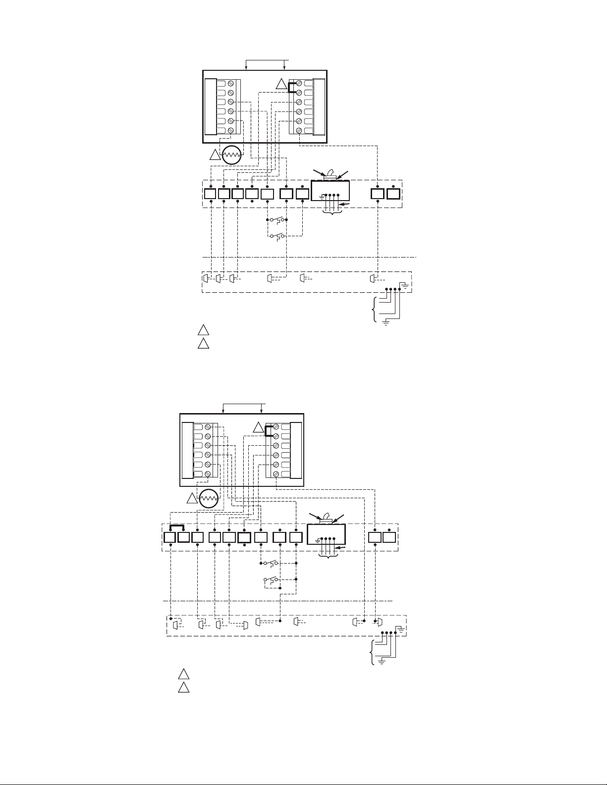
Fig. 9. Typical hookup of single-stage heat pump with auxiliary/backup heat (2H/1C heat pump).
Fig. 10. Typical hookup of multistage heat pump with auxiliary/backup heat (3H/2C heat pump).
PM-A
1
M22641
FACTORY INSTALLED JUMPER.
OPTIONAL OUTDOOR OR INDOOR REMOTE SENSOR. AVAILABLE
ON SELECT MODELS. WIRES MUST HAVE A CABLE SEPARATE
FROM THE THERMOSTAT CABLE.
1
2
2
RC
S1
R
S2
O
Y
G
B
HEAT PUMP
T
T
B/C
W2
W1
GYR
AIR
HANDLER
Y
B
HEAT PUMP
O.D. SECTION
(SINGLE STAGE)
TO POWER SUPPLY
PER LOCAL CODES
(3 PH
ONLY)
INDOOR
OUTDOOR
W1
Y2
F
X2
O
R
O
W3
TO POWER
SUPPLY PER
LOCAL
CODES AND
AS DEFINED
IN FIELD
WIRING TABLE
SUPPL. HTR.
CONTROL BOX
I-PF
REQ.
FOR
3 PH
ODT-1
ODT-2
BR(T)X2/BK
PM-A
1
M22642
FACTORY INSTALLED JUMPER.
OPTIONAL OUTDOOR OR INDOOR REMOTE SENSOR. AVAILABLE ON SELECT MODELS.
WIRES MUST HAVE A CABLE SEPARATE FROM THE THERMOSTAT CABLE.
1
2
2
RC
S1
R
S2
O
Y
G
B
HEAT PUMP
T
T
B/C
W1
G
OYR
VARIABLE
SPEED AIR
HANDLER
B
TO POWER SUPPLY
PER LOCAL CODES
(3 PH
ONLY)
INDOOR
OUTDOOR
W1
Y2
F
X2
YLO
R
X2/BK
ODT-1
ODT-2
F
BR(T)
W2
TO POWER
SUPPLY PER
LOCAL
CODES AND
AS DEFINED
IN FIELD
WIRING TABLE
SUPPL. HTR.
CONTROL BOX
I-PF
REQ.
FOR
3 PH
W3
Y2
O
HEAT PUMP
O.D. SECTION
(TWO STAGE)
BK
Y1
TCONT802AS32DA TOUCH SCREEN AND TCONT803AS32DA TOUCH SCREEN WITH DEHUMIDIFICATION
Pub. No. 18-HD25D19-3
5 69-1790—3
Fig. 11. Typical hookup of multistage two-step scroll heat pump with auxiliary/backup heat (3H/2C heat pump).
Fig. 12. Typical hookup of singe-stage heat pump with non-variable speed gas furnace.
1
M24230
FACTORY INSTALLED JUMPER.
OUTDOOR REMOTE SENSOR. WIRES MUST HAVE A CABLE
SEPARATE FROM THE THERMOSTAT CABLE.
THE INSTALLER MUST JUMPER AT THE LVTB “R” TO “O”.
1
2
2
RC
S1
R
S2
O
Y
G
B
HEAT PUMP
T
B/C
G
Y
Y
LO
BK R
VARIABLE SPEED
AIR HANDLER
B
16 SEER
HEAT PUMP
O.D. SECTION
(TWO STEP)
TO POWER SUPPLY
PER LOCAL CODES
(3 PH
ONLY)
INDOOR
OUTDOOR
W1
Y2
F
X2
O
Y2
W1
Y1
W2
R
O
BR(T)
X2/BK
3
3
W1
W2
G
Y
B/C
R
T
1
1
2
FACTORY INSTALLED JUMPER.
OUTDOOR REMOTE SENSOR. WIRES MUST HAVE A
CABLE SEPARATE FROM THE THERMOSTAT CABLE.
Y
R O BR(T)X2/BK
B
HEAT PUMP
O.D. SECTION
(SINGLE STAGE)
2
NON-V.S.
ONE OR TWO
STAGE GAS
FURNACE
INDOOR
OUTDOOR
HEAT PUMP
RC
R
O
Y
G
B
Y2
F
X2
W1
S1
S2
TO POWER SUPPLY
PER LOCAL CODES
(3 PH
ONLY)
M24200
TCONT802AS32DA TOUCH SCREEN AND TCONT803AS32DA TOUCH SCREEN WITH DEHUMIDIFICATION
Pub. No. 18-HD25D19-3
69-1790—3 6
Fig. 13. Typical hookup of single-stage heat pump with two stage variable speed gas furnace
(2H/1C heat pump).
W1 W2G YB/CR
T
1
1
2
FACTORY INSTALLED JUMPER.
OUTDOOR REMOTE SENSOR. WIRES MUST HAVE A
CABLE SEPARATE FROM THE THERMOSTAT CABLE.
Y
R O BR(T)BR/X2
OR BK
B
HEAT PUMP
O.D. SECTION
(SINGLE STAGE)
2
VARIABLE
SPEED
TWO STAGE
FURNACE
INDOOR
OUTDOOR
HEAT PUMP
RC
R
O
Y
G
B
Y2
F
X2
W1
S1
S2
TO POWER SUPPLY
PER LOCAL CODES
(3 PH
ONLY)
M24201
1
BK
O
Y
LO
 Loading...