

Honeywell TC846A1005 Installation Instructions Manual

INSTALLATION INSTRUCTIONS
CAUTION
TC846A1005
Intelligent Laser Smoke Sensor
SPECIFICATIONS
Operating Voltage Range: 15 to 32 VDC
Standby Current: 330µA @ 24 VDC (one communication every 5 sec. with LED blink enabled)
Max. Alarm Current (LED on): 6.5 mA @ 24 VDC
Operating Humidity Range: 10% to 93% Relative Humidity, noncondensing
Operating Temperature Range: 0°C to 38°C (32°F to 100°F); U.S.
–10°C to 50°C (14°F to 122°F); Europe
Height: 1.7 inches (43 mm) installed in B210LP Base
Diameter: 6.1 inches (155 mm) installed in B210LP Base
4.1 inches (104 mm) installed in B501 Base
Weight: 5.0 oz. (142 g)
Before installing sensors, please thoroughly read the System Smoke Detector
Application Guide, which provides detailed information on sensor spacing,
placement, zoning, and special applications. Copies of this manual are available from Honeywell.
NOTICE: This manual should be left with the owner/user of this equipment.
IMPORTANT: This sensor must be tested and maintained regularly following
NFPA requirements. It should be cleaned at least once a year.
GENERAL DESCRIPTION
Model TC846A1005 is a plug-in type smoke sensor that uses a laser based
sensing chamber. The sensor uses analog-addressable communications to
transmit smoke density and other information to the control panel. Rotary-decade switches are provided for setting the sensor’s address. Two LEDs on the
sensor are controlled by the panel to indicate sensor status. An output is provided for connection to an optional remote LED annunciator (P/N RA400Z/
RA100Z).
The TC846A1005 requires compatible addressable communications to
function properly. Connect these sensors to listed-compatible control panels only.
SPACING
Honeywell recommends spacing sensors in compliance with NFPA 72. In low
air flow applications with smooth ceilings, space sensors 30 feet apart. For
specific information regarding sensor spacing, placement, and special applications, refer to NFPA 72.
WIRING INSTRUCTIONS
All wiring must be installed in compliance with the National Electrical Code,
applicable local codes, and any special requirements of the Authority Having
Jurisdiction. Proper wire gauges should be used. The installation wires should
be color-coded to limit wiring mistakes and ease system troubleshooting. Improper connections will prevent a system from responding properly in the
event of a fire.
REMOVE POWER FROM THE COMMUNICATION LINE BEFORE INSTALLING SENSORS.
All wiring must conform to applicable local codes, ordinances, and regulations.
1. Wire the sensor base (supplied separately) per the wiring diagram, see
Figure 1.
2. Set the desired address on the sensor address switches, see Figure 2.
3. Install the sensor into the sensor base. Push the sensor into the base
while turning it clockwise to secure it in place.
4. After all sensors have been installed, apply power to the control unit and
activate the communication line.
5. Test the sensor(s) as described in the TESTING section of this manual.
Dust covers provide limited protection against airborne dust particles during
shipping. Dust covers must be removed before the sensors can sense smoke.
Remove sensors prior to heavy remodeling or construction.
TESTING
Before testing, notify the proper authorities that the system is undergoing
maintenance, and will temporarily be out of service. Disable the system to
prevent unwanted alarms.
All sensors must be tested after installation and periodically thereafter. Testing methods must satisfy the Authority Having Jurisdiction (AHJ). Sensors
offer maximum performance when tested and maintained in compliance with
NFPA 72.
The sensor can be tested in the following ways:
A. FUNCTIONAL: MAGNET TEST (P/N M02-04-01 OR M02-09-00)
This sensor can be functionally tested with a test magnet. The test magnet
electronically simulates smoke in the sensing chamber, testing the sensor electronics and connections to the control panel.
1. Hold the test magnet in the magnet test area as shown in Figure 3.
2. The sensor should alarm the panel.
Two LEDs on the sensor are controlled by the panel to indicate sensor status.
Coded signals, transmitted from the panel, can cause the LEDs to blink, latch
on, or latch off. Refer to the control panel technical documentation for sensor
LED status operation and expected delay to alarm.
B. SMOKE ENTRY: AEROSOL GENERATOR (GEMINI 501)
The GEMINI model 501 aerosol generator can be used for smoke entry testing.
Set the generator to represent 4%/ft. to 5%/ft. obstruction as described in the
GEMINI 501 manual. Using the bowl shaped applicator, apply aerosol until
the panel alarms.
A sensor that fails any of these tests should be cleaned as described under
CLEANING, and retested. If the sensor fails after cleaning, it must be replaced
and returned for repair.
When testing is complete, restore the system to normal operation and notify
the proper authorities that the system is back in operation.
Honeywell House, Arlington Business Park
I56-0060-007
1985 Douglas Drive North
Golden Valley, MN 55422 USA
customer.honeywell.com
Honeywell Control Systems Ltd
Bracknell, Berkshire RG12 1EB UK
1 I56-0060-007
10-03
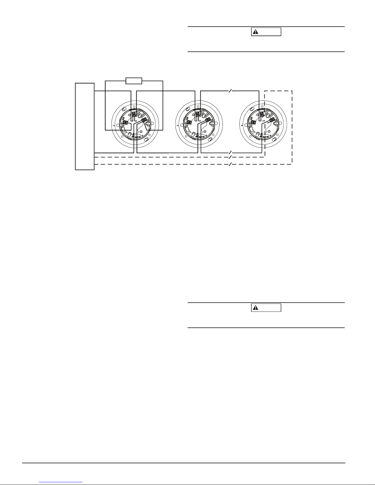
LISTED COM
CONTROL
CAUTION: DO NOT LOOP WIRE
FIGURE 1. WIRING DIAGRAM
CAUTION
CAUTION
Do not loop wire under terminal 1 or 2. Break wire run to provide supervision
of connection.
REMOTE
ANNUNCIATOR
+-
UNDER TERMINAL 1 OR 2.
BREAK WIRE RUN TO PROVIDE
SUPERVISION OF CONNECTIONS.
(+)
PATIBLE
PANEL
(–)
(–)
UL
(+)
CLEANING
It is recommended that the detector be removed from its mounting base to
facilitate cleaning. The detector is cleaned as follows:
NOTE: Before removing the detector, notify the proper authorities that the
smoke detector system is undergoing maintenance and will be temporarily
out of service. Disable the zone or system undergoing maintenance to prevent
unwanted alarms.
1. Remove the detector cover by prying away the four side tabs with a
small-bladed screwdriver, and then pulling the cover from the base.
2. Vacuum the screen carefully without removing it. If further cleaning is
required continue with Step 3, otherwise skip to Step 7.
3. Remove the screen/chamber cover assembly by pulling it straight out
(see Figure 4).
4. Clean the chamber by vacuuming or blowing out dust and particles.
5. Replace the sensing chamber cover, aligning the arrow on the top with
arrow on the printed circuit board.
6. To replace the screen, place it over the chamber assembly, turning it until
it snaps into place.
7. Replace the cover using the LEDs to align the cover and then gently
pushing it until it locks into place.
8. Reinstall the detector.
9. Test the detector as described in TESTING.
10. Reconnect disabled circuits.
11. Notify the proper authorities that the system is back on line.
2
1
3
CLASS A OPTIONAL WIRING
2
1
3
LASER SAFETY INFORMATION
This smoke detector does not produce any hazardous laser radiation and is
certified as a Class 1 laser product under the U.S. Department of Health and
Human Services (DHHS) Radiation Performance Standard according to the
Radiation Control for Health and Safety Act of 1968.
Any radiation emitted inside the smoke detector is completely within the protective housings and external covers. The laser beam cannot escape from the
detector during any phase of operation.
The Center of Devices and Radiological Health (CDRH) of the U.S. Food and
Drug Administration implemented regulations for laser products on August 2,
1976. These regulations apply to laser products manufactured after August 1,
1976. Compliance is mandatory for products marketed in the United States.
Use of controls, adjustments, or performance of procedures other than those
specified in this manual may result in hazardous radiation exposure.
SPECIAL NOTE REGARDING SMOKE DETECTOR GUARDS
Smoke detectors are not to be used with detector guards unless the combination has been evaluated and found suitable for that purpose.
2
1
3
C0129-02
2 I56-0060-007
10-03
 Loading...