

Honeywell TC844A1015 Installation Instructions Manual
FCC Statement
This device complies with part 15 of the FCC Rules. Operation is subject to the following two conditions: (1) This device may not cause harmful interference, and (2) this
device must accept any interference received, including interference that may cause undesired operation.
NOTE: This equipment has been tested and found to comply with the limits for a Class B digital device, pursuant to Part 15 of the FCC Rules. These limits are designed to
provide reasonable protection against harmful interference in a residential installation. This equipment generates, uses and can radiate radio frequency energy and, if not
installed and used in accordance with the instructions, may cause harmful interference to radio communications. However, there is no guarantee that interference will not
occur in a particular installation. If this equipment does cause harmful interference to radio or television reception, which can be determined by turning the equipment off and
on, the user is encouraged to try to correct the interference by one or more of the following measures:
– Reorient or relocate the receiving antenna.
– Increase the separation between the equipment and receiver.
– Connect the equipment into an outlet on a circuit different from that to which the receiver is connected.
– Consult the dealer or an experienced radio/TV technician for help.
H500-32-00 4 I56-1982-004R
© 2006 Honeywell
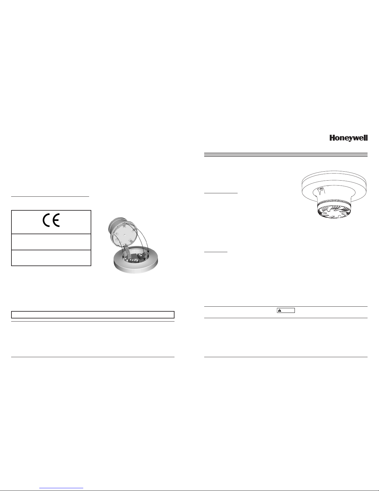
1. Grasp the Filtrex housing with one hand and the cover with the other. Turn the cover counterclockwise fully (approx. 30 degrees)
and remove cover by pulling it away from detector unit (see Figure 4).
2. Replace with new filter and cover assembly. The cover is keyed so it fits in place only one way. Turn the cover clockwise until it stops.
NOTE: The base is equipped with an optional tamperproof feature which can be used to prevent unintentional removal of Filtrex while
replacing the filter.
If a clogged filter was the cause of the trouble condition, normal detector operation should resume automatically within five minutes. If
the trouble condition persists, the detector must be returned for repair or replacement.
Installing Filtrex into Base
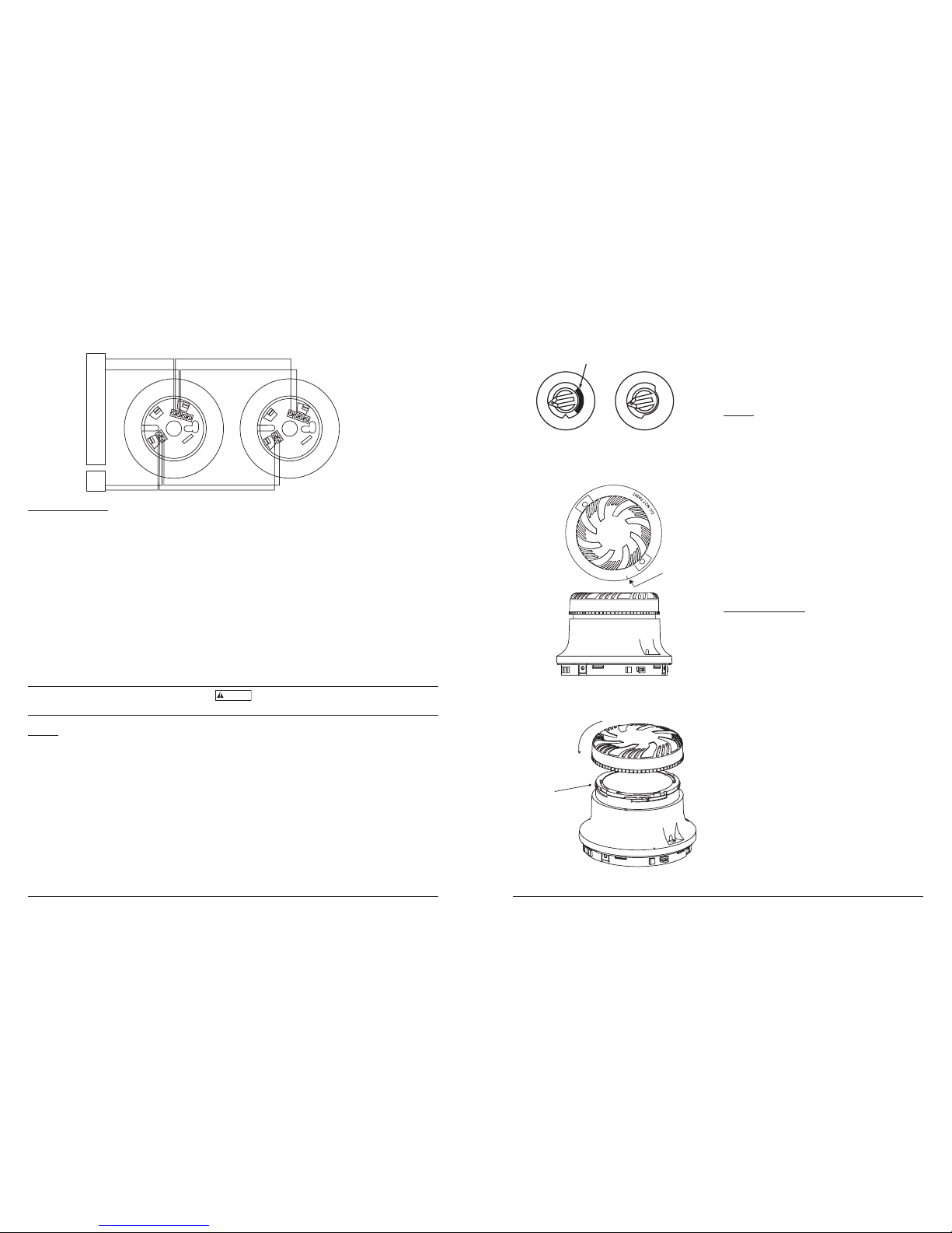
1. Align the detector at a right angle to the base, with the five wires and connector adjacent to the connector receptacle as shown in
Figure 5.
2. Plug the wired connector into the receptacle.
3. Rotate the detector into the base, making sure detector and base keyed fit is lined up. Turn the detector clockwise until it snaps
into place.
IMPORTANT: Filtrex will only operate with 14507371-008/B524FTXE Mounting Base.
SPECIAL NOTE REGARDING SMOKE DETECTOR GUARDS
Smoke detectors are not to be used with detector guards unless the combination has been evaluated and found suitable for that purpose.
Figure 5: Installing Filtrex detector into base:
Before installing sensors, please thoroughly read the Guide for Proper Use
of System Smoke Detectors, which provides detailed information on sensor
spacing, placement, zoning, and special applications. Copies of this guide
are available from Honeywell.
NOTICE: This manual should be left with the owner/user of this equipment.
IMPORTANT: This sensor must be tested and maintained regularly following
NFPA 72 requirements. It should be cleaned at least once a year.
GENERAL DESCRIPTION
Filtrex® uses a small air intake fan and a high density replaceable filter. Air
and smoke are drawn into a photoelectric sensing chamber while airborne
particulate and water mist are removed. The addressable-analog detector
transmits an analog representation of smoke density over a communication
line to a control panel. FlashScan Technology is a new communication protocol that greatly enhances the speed of communication between analog intelligent devices. Rotary-decade switches are provided for setting the sensor’s
address. Two LEDs on the sensor are controlled by the panel to indicate
sensor status.
The Filtrex smoke detector is intended for use in normal environmental conditions, where dust and other airborne particulate are present at elevated levels. These elevated levels tend to cause false alarms and high maintenance in standard detectors. Filtrex provides
a protective enclosure for a photoelectric smoke detector chamber and allows smoke detection in areas where heat detection was the
only practical alternative for fire sensing.
Filtrex requires compatible addressable communications to function properly. Connect this detector to listed-compatible control panels only.
SPECIFICATIONS
Operating Voltage Range: 15 to 32 VDC
Detector Current: 230 µA @ 24 VDC (without communication)
285 µA @ 24 VDC (one communication every 5 sec. with LED enabled)
Auxiliary Power Supply Voltage: 15 to 30 VDC filtered; Ripple voltage may not drop below 15 volts.
Auxiliary Power Supply Current
Peak: 123 mA max.
Average: 27 mA max.
Operating Humidity Range: 10% to 93% Relative Humidity, non-condensing
Operating Temperature Range: 0° to 50°C (32° to 122°F)
Height: 2.8 inches (43 mm)
Diameter: 6.1 inches (155 mm) installed in 14507371-008
4.0 inches (102 mm) installed in B524FTXE
Weight: 7.3 oz. (207 g)
Mounting Base: Requires 14507371-008 (U.S.), B524FTXE (Europe)
WARNING
Filtrex is not designed to operate in explosive environments.
H500-32-00 1 I56-1982-004R
Honeywell, 1985 Douglas Drive North, Golden Valley, MN 55422
Model TC844A1015 Filtrex Intelligent Photoelectronic Sensor
with FlashScan Technology
C0193-00
I56-1982-004R
0845-CPD.232.1427
SYSTEM SENSOR
3825 OHIO AVENUE, ST. CHARLES
IL, 60174 8021 U.S.A.
EN54-7
Model TC844A1015
Filtrex Point Optical Smoke Sensor for Harsh Areas
Installation Instructions
Please refer to insert for the Limitations of Fire Alarm Systems
CAUTION: Do not loop wire
under terminal 1 or 2. Break
wire run to provide supervision
of connections.
H500-32-00 3 I56-1982-004R
Figure 4. Replacing the filter cover:
Figure 3. Test magnet position:
Figure 2. Rotary decade address switches:
C0162-00
A detector that fails any of these tests should be retested. If the
detector still fails any test, have its filter replaced (see instructions
below) and retested. Finally, if the detector continues to fail after
replacing the filter, it must be returned for repair or replacement.
When test ing is complete , restore the sys tem to normal ope ration and not ify the proper authorities that the syst em is back
in opera tion.
TESTING
The unique design of Filtrex eliminates the need for typical detector
cleaning. The only maintenance necessary is replacing the filter,
which is signaled by a trouble condition at the panel (see below).
Filtrex has been designed to maximize the amount of time before
maintenance is required. Filtrex utilizes a replaceable filter that
may become clogged over time. Filtrex detector monitors itself to
insure that the filter has not become clogged. Because environmental conditions can vary significantly, the amount of time before
maintenance could vary significantly as well. To fully understand
maintenance requirements of Filtrex in its installed location, it is
recommended that the following test program be conducted.
1. Install the Filtrex detector in the desired location.
2. Connect the Filtrex detector to the fire alarm control panel.
3. Maintain a record for at least 90 days of any maintenance
performed on or required by Filtrex.
4. At the end of the test period, use the record to develop and
schedule maintenance. Filtrex should be serviced at regular
intervals to insure that the fire alarm system provides continuous protection.
REPLACING THE FILTER
IMPORTANT: When the filter becomes too clogged to draw ade-
quate air into Filtrex, power is automatically cut from the detector,
sending a trouble signal to the fire control panel. After 5 minutes,
power is restored to the detector for 72 hours. After 72 hours,
power is cut again and the detector will remain off-line until the
filter is replaced.
NOTE: The unit has two filters. The replaceable filter is inside the
cover. A permanent filter is mounted to the unit.
H500-32-00 2 I56-1982-004R
Figure 1. Wiring diagram:
WIRING INSTRUCTIONS
All wiring must be installed in compliance with the National Electrical Code, applicable local codes, and any special requirements of
the Authority Having Jurisdiction. Proper wire gauges should be used. The installation wires should be color-coded to limit wiring mistakes and ease system troubleshooting. Improper connections will prevent a system from responding properly in the event of a fire.
NOTE: Although the TC844A1015 is an intelligent sensor, a separate pair of wires is required for power. This power must be provided
from a listed fire alarm power supply.
Remove power from the communication line before installing detectors.
All wiring must conform to applicable local codes, ordinances, and regulations.
1. Wire the sensor base per the wiring diagram, please see Figure 1.
2. Set the desired address on the sensor address switches, please see Figure 2.
NOTE: Some panels support extended addressing. In order to set the sensor above address 99 on compatible systems, carefully
remove the stop on the upper rotary switch with thumb as shown in Figure 2.
3. Insert 5-wire connector on mounting base into 5-pin connector on Filtrex unit. Install the detector into the sensor base. Push the
detector into the base while turning it clockwise to secure it in place. (Please see Figure 5 and INSTALLING FILTREX INTO BASE
on page 4 for specific directions.
4. After all detectors have been installed, turn on the detector power supply, then apply power to the control unit and activate the
communication line.
5. Test the detector(s) as described in the TESTING section of this manual.
CAUTION
Dust cover must be removed before the detector can sense smoke.
TESTING
Before testing, notify the proper authorities that the system is undergoing maintenance, and will temporarily be out of service. Disable
the system to prevent unwanted alarms.
All detectors must be tested after installation and periodically thereafter. Testing methods must satisfy the Authority Having Jurisdiction
(AHJ). Detectors offer maximum performance when tested and maintained in compliance with NFPA 72.
The sensor can be tested in the following ways:
A. Functional: Magnet Test (P/N M02-04-01 or M02-09-00)
This detector can be functionally tested with a test magnet. The test magnet electronically simulates smoke in the sensing cham
-
ber, testing the detector electronics and connections to the control panel.
1. Hold the test magnet in the magnet test area as shown in Figure 3.
2. The detector should alarm the panel. Two LEDs on the detector are controlled by the panel to indicate sensor status. Coded
signals, transmitted from the panel, can cause the LEDs to blink, latch on, or latch off. Refer to the control panel technical
documentation for detector LED status operation and expected delay to alarm.
B. Smoke Entry: Aerosol Generator
Aerosol generators for smoke entry testing are available from a number of third party manufacturers (e.g., Gemini Scientific). Fol
-
lowing the manufacturer’s instructions, apply aerosol until the panel alarms.
TEST MAGNET
MARKER
Cover is keyed to
fit into 4 matching
sized slots.
Alignment marks
are provided on the
cap and top of the
permanent filter.
LISTED COMPATIBLE CONTROL PANEL
AUX.
POWER
SUPPLY
+
+
–
–
A
UX
+
AUX
–
A
UX
+
AUX
–
2
(
–
)
3(
R
A)
4(S)
1
(
+)
1
(+
)
2(
–
)
3(R
A
)
4(
S
)
TENS
Breakaway Stop
ONES
9
10
11
12
13
14
15
8
7
6
5
4
3
2
1
0
9
8
7
6
5
4
3
2
1
0
C0845-00
C0191-00
C0121-00
C0190-00
 Loading...