

Honeywell TC810E1040, TC810E1040-KO, TC810E1057 Installation Instructions Manual
H200-93-01 I56-2059-014
DoP Ref: 0786-CPD-20341
EN54-17: 2005
EN54-18: 2005
Pittway Tecnologica S.r.l,
Via Caboto 19/3,
34147 Trieste, Italy
0786 07
Honeywell Building Solutions, Honeywell House, Arlington Business Park, Bracknell, Berkshire, RG12 1EB, UK
E N G L I S H
1
3
4
5
6
2
7
8
9
10
11
12
0
0
1
1
2
2
3
3
4
455
6
6
7
7
8
8
9
9
This manual is intended as a quick reference installation guide. Please refer
to the control panel installation manual for detailed system information.
GENERAL INFORMATION
The TC810E series of modules are a family of microprocessor controlled
interface devices permitting the monitoring and/or control of auxiliary
devices. The TC810E1040, TC810E1040-KO and TC810E1057 are output
modules, providing 250VAC 5A rated voltage free contacts, both normally
open and normally closed.
SPECIFICATIONS
Operating Voltage Range: 15 to 30VDC (Min 19.5VDC to ensure LED
operation - TC810E1040-KO 17.5VDC)
Maximum Standby Current (µA): 275µA - No Communication
445µA - Communication LED blink enabled - 5 secs
375µA - Read 16 sec. LED blink 8 sec
Fault Current: 8.8mA (Yellow LED illuminated)
Coil Activation/Deactivation Current: 76mA Maximum for 12mS
Relay Contact Rating: 5A, at 30VDC, 5A at 250VAC
Maximum rated continuous current with the isolator closed (Ic max): 1A
Maximum rated isolator current (under short circuit) (Is max): 1A
Maximum leakage current (IL max) with the isolator open (isolated state): 15mA
Maximum series impedance with the isolator closed (Zc max): 170 m ohm at 15Vdc
Operating Temperature: -20°C to 60°C
Humidity: 5% to 95% Relative Humidity
Dimensions TC810E1040 and TC810E1040-KO: 134mm(H) x 139mm(W) x 40mm(D)
Dim en si on s TC 81 0E 10 57 : 127mm(H) x 76mm(W) x 48mm(D) (Including terminals)
Weight TC810E1040 and TC810E1040-KO: 195g
Weight TC810E1057: 140g
Maximum Wire Gauge 1.5mm² - TC810E1040 (-KO), 2.5mm² - (-DIN)
INSTALLATION
Note: These modules must only be connected to control panels using
compatible proprietary analogue addressable communication
protocols for monitoring and control.
CAUTION
Disconnect loop power before installing modules or sensors.
High voltages may be present on terminals 7 to 12.
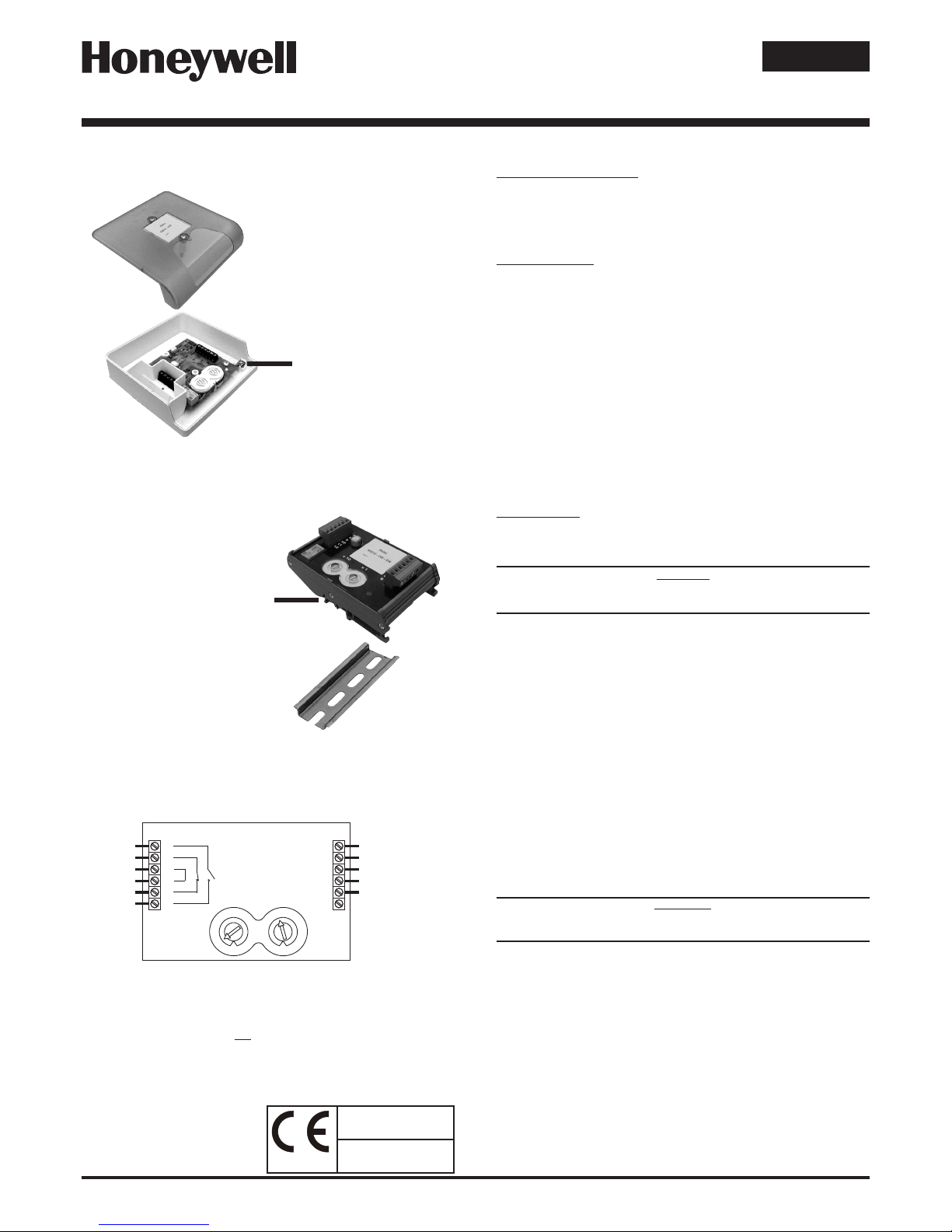
TC810E1040 and TC810E1040-KO
1. TheTC810E1040(-KO)includesacustomlowprolesurface-mounting
boxwithseveraloptionsforxingcentres.Toaccessallxingpoints,
and the rear cable entry knock out, the circuit board must be removed.
It is held in place by two screws through the circuit board. Ensure that
thesescrewsarereplacedwhenrettingthecircuitboard.
2. If rear cable entry is not required, the box has several cover drill points
permitting the entry of cables using suitable glands.
3. Wiring to the TC810E1040(-KO) is made via two 6 way terminal strips
on the module circuit board, capable of supporting conductors up to
1.5mm².Seegure2forconnections.
4. An earthing terminal is provided in the surface mount box for connection
oftheloopcablescreen,ifused,toensurecontinuity.Seegure1a.
TC810E1057
1. TC810E1057 mounts onto standard 35mm x 7.5mm "Top Hat" DIN rail.
It must be mounted in a suitable cabinet meeting the applicable safety
standards.
2. Wiring to the TC810E1057 is via plug in type terminals capable of
supportingconductorsupto2.5mm².Seegure2forconnections.
WARNING
Ensure that the correct terminals are used for the loop and
switched voltage as damage may result from incorrect usage.
For both modules, the address is selected by means of rotary decade
address switches (see gure 2), accessed at the front of the module. A
screwdriver should be used to rotate the wheels to select the desired
address. (Note: The number of addresses available will be dependent on
panel capability, check the panel documentation for information on this.)
Short Circuit Isolators
All TC810E series modules are provided with short circuit monitoring and
isolators on the intelligent loop. If required the isolators may be wired out of
the loop to facilitate the use of the modules on high current loaded loops, for
example if sounders are used. To achieve this, the loop out positive should
be wired to terminal 5 rather than terminal 2.
Figure 1a: TC810E1040(-KO) Surface Mount
Output Module with 240V Relay Contacts
Figure 1b: TC810E1057 Din Rail Mounted
Output Module with 240V Relay Contacts.
TO MOUNT, LOCATE LUG OVER TOP
OF RAIL AND ROTATE THE MODULE
DOWN TO CLIP INTO PLACE.
TO REMOVE, PUSH UPWARDS, AND
ROTATE TOP OF MODULE AWAY
FROM RAIL.
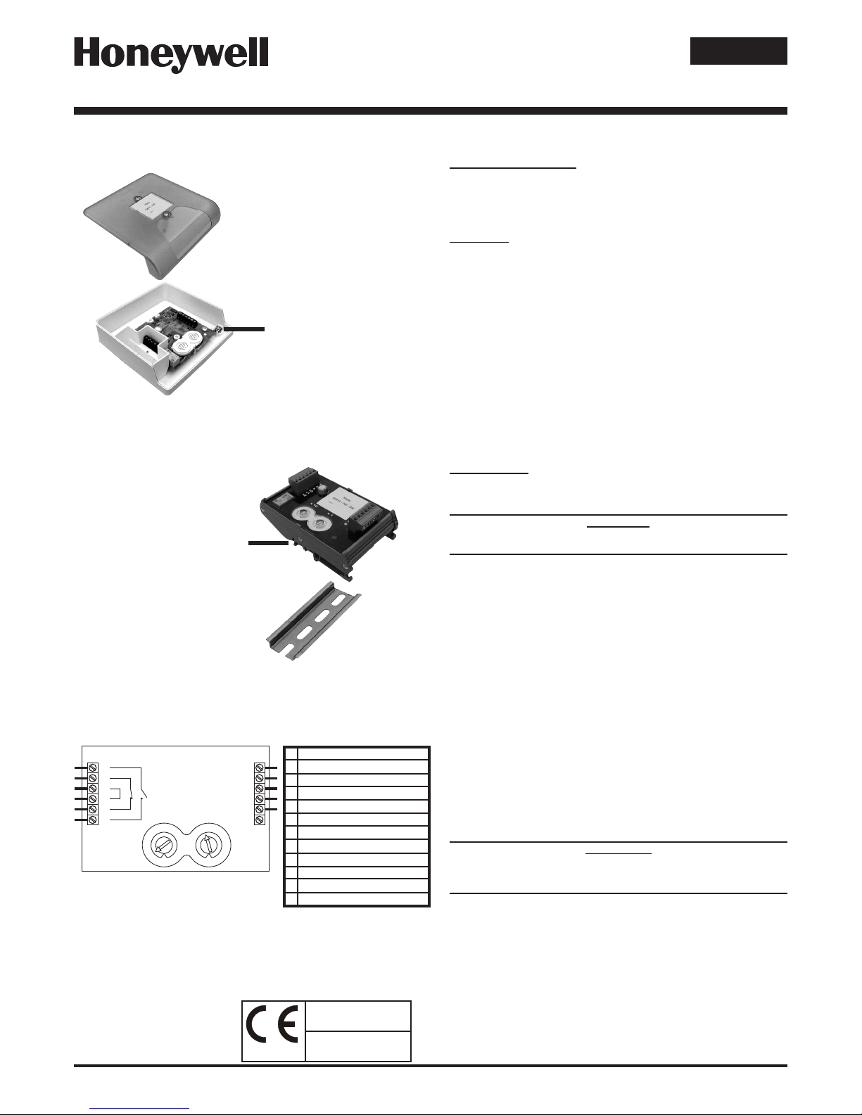
Figure 2: Module Wiring
NOTE: Wiring is the same for TC810E1040(-KO) and TC810E1057
Loop -, Out
Loop +, Out - See Note 1
Loop -, In
Loop +, In
Loop +, Out - See Note 1
T6 - Not Connected
Relay 1, N/O
Relay 2, N/C
Ground
Ground
Relay 2, N/C
Relay 1, N/O
TENS UNITS
LOOP CABLE SCREEN TERMINAL
TC810E1040, TC810E1040-KO
AND TC810E1057
INSTALLATION INSTRUCTIONS FOR MAINS SWITCHING OUTPUT MODULES
ROTARY DECADE ADDRESS SWITCHES
Notes:
1. If short circuit isolation is not required, then the loop output should
be wired to terminal 5 rather than terminal 2. Terminal 5 is internally
connected directly to terminal 4.
2. In order to meet the requirements of European Safety Standards,
ensure that all cables carrying voltages in excess of 48V are suitably
fused.
H200-93-01 I56-2059-014
DoP Ref: 0786-CPD-20341
EN54-17: 2005
EN54-18: 2005
Pittway Tecnologica S.r.l,
Via Caboto 19/3,
34147 Trieste, Italy
0786 07
Honeywell Building Solutions, Honeywell House, Arlington Business Park, Bracknell, Berkshire, RG12 1EB, UK
TC810E1040, TC810E1040-KO E TC810E1057
ITALIANO
1
3
4
5
6
2
7
8
9
10
11
12
0
0
1
1
2
2
3
3
4
455
6
6
7
7
8
8
9
9
Il presente manuale è stato concepito come guida all'installazione di rapida
consultazione. Per informazioni dettagliate sul sistema, consultare il manuale
di installazione fornito del pannello di controllo.
INFORMAZIONI GENERALI
I moduli della serie TC810E sono una famiglia di dispositivi di interfaccia
controllati da un microprocessore che consentono di monitorare e/o controllare
dispositivi ausiliari. I modelli TC810E1040, TC810E1040-KO e TC810E1057
sono moduli di uscita dotati di contatti liberi con tensione nominale di 250 V
CA a 5A, uno normalmente aperto, l'altro normalmente chiuso.
SPECIFICHE
Range tensione operativa: da 15 a 30 V CC (Per garantire il funzionamento del
LED servono almeno 19,5 V CC - (-KO 17,5 V C C))
Massima corrente di standby (µA): 275 µA - Nessuna comunicazione
445 µA - Comunicazione con lampeggiamento abilitato - 5 s
375 µA - Read Presence ogni 16s con lampeggio ogni 8s
Corrente di guasto: 8,8 mA (LED giallo illuminato)
Corrente di Attivazione/Disattivazione bobina: 76 mA max. per 12 mS
Potenza contatti del relè: 5 A a 30 V CC, 5 A a 250 V CA
Massima corrente continua stimata con isolatori chiusi (Ic max): 1A
Massima corrente di attivazione stimata in caso di corto circuito (Is max): 1A
Massima corrente di perdita con isolatori aperti (IL max): 15mA
Massima impedenza serie con isolatori chiusi (Zc max): 170 m ohm at 15Vdc
Temperatura di servizio: da -20°C a 60°C
Umidità: Umidità relativa compresa tra il 5% e il 95% (in assenza di condensa)
Dimensioni del modello TC810E1040(-KO): 134 mm (H) x 139 mm (L) x 40 mm (P)
Dimensioni del modello -DIN:127 mm (H) x 76 mm (L) x 48 mm (P) (compresi i morsetti)
Peso del modello TC810E1040(-KO): 195 gr.
Peso del modello TC810E1057: 140 gr.
Massimo calibro del lo: 1,5 mm² - TC810E1040(-KO), 2.5mm² - (-DIN)
INSTALLAZIONE
Nota: Questi moduli possono essere collegati esclusivamente a pannelli di
controllo dotati di opportuno protocollo di comunicazione proprietario,
indirizzabile ed analogico, compatibile con funzioni di monitoraggio e controllo.
ATTENZIONE
Prima di installare i moduli o i sensori, scollegare l'alimentazione del circuito.
Possibilità di alta tensione in corrispondenza dei morsetti da 7 a 12.
TC810E1040 e TC810E1040-KO
1. Il modello TC810E1040 ( -KO ) comprende una scatola per montaggio
su supercie personalizzato a basso prolo con diverse opzioni di punti
di ssaggio. Per accedere a tutti i punti di ssaggio e all'espulsore per
ingresso del cavo posteriore, è necessario rimuovere il circuito stampato.
Esso è ssata al fondo della scatola per mezzo di due viti.
2. Se l'ingresso cavi posteriore non è necessario, fori possono essere praticati
sul perimetro della scatola consentendo l'ingresso dei cavi mediante
appositi premistoppa.
3. Il cablaggio del modello TC810E1040 ( -KO ) viene effettuato per mezzo
di 2 morsetti a 6 vie presenti sul circuito stamapo del modulo. Sono
supportati conduttori no a 1,5 mm² . Per informazioni su come effettuare
le connessioni ved. gura 2.
4. La scatola per montaggio su supercie contiene anche un terminale di
messa a terra per la connessione dello schermo del cavo del circuito, se
utilizzato, che garantisce continuità. Ved. gura 1a.
TC810E1057
1. Il modello TC810E1057 è montato su un binario DIN "Top Hat" standard di
35 mm x 7,5 mm. È necessario montarlo in un armadio idoneo conforme
agli standard di sicurezza applicabili.
2. Il cablaggio del modello TC810E1057 viene effettuato mediante morsetti
di tipo a spina in grado di supportare conduttori no a 2,5 mm². Per
informazioni su come effettuare le connessioni ved. gura 2.
AVVERTENZA
Accertarsi che vengano utilizzati i morsetti del tipo corretto per il
loop e per la tensione applicata in quanto l'uso improprio potrebbe
provocare danni.
Per entrambi i moduli l'indirizzo viene scelto per mezzo di switch rotativi per
indirizzamento decimale (ved. gura 2), a cui si accede dalla parte anteriore
del modulo. Utilizzare un cacciavite per girare le ruote e quindi selezionare
l'indirizzo desiderato. (Nota: il numero di indirizzi disponibili dipende dalla
capacità del pannello: per informazioni a questo proposito consultare la
documentazione relativa al pannello.)
Isolatori di corto circuito
Tutti i moduli della serie TC810E sono dotati di un dispositivo di monitoraggio
e di isolatori di corto circuito sul loop intelligente. Se necessario, è possibile
bypassare gli isolatori al loop in modo da agevolare l'utilizzo dei moduli in loop
ad alta corrente se, ad esempio, si utilizzano avvisatori acustici. A questo
scopo, cablare l'uscita loop positiva al morsetto 5 anziché al morsetto 2.
Figura 1a: Modulo di uscita con montaggio su supercie
TC810E1040 ( -KO )con contatti di relè da 240 V
Figura 1b: Modulo di uscita montato su binario Din
TC810E1057 con contatti di relè da 240 V.
PER IL MONTAGGIO,
POSIZIONARE L'ALETTA
SULLA PARTE SUPERIORE
DEL BINARIO E RUOTARE
IL MODULO VERSO IL
BASSO FINO ALLO SCATTO
IN POSIZIONE.
PER RIMUOVERE IL
MODULO, SPINGERE
VERSO L'ALTO E RUOTARE
LA PARTE SUPERIORE DEL
MODULO E RIMUOVERLO
DAL BINARIO.
Figure 2: Cablaggio del modulo
NOTA: Il cablaggio è identico per entrambi i modelli TC810E1040 (-KO)
e TC810E1057.
DECINE UNITÀ
Note:
1. Se non è richiesto alcun isolamento da corto circuito, collegare l'uscita loop al
morsetto 5 e non al 2. Il morsetto 5 è collegato internamente al morsetto 4.
2. Al ne di soddisfare i requisiti degli Standard di sicurezza europei, vericare che
tutti i cavi soggetti ad eccessi di tensione pari a 48V siano adeguatamente forniti
di fusibili.
TERMINALE PER SCHERMO
DEL CAVO DEL CIRCUITO
ISTRUZIONI PER L'INSTALLAZIONE DI MODULI
DI USCITA A COMMUTAZIONE DI RETE
LOOP -, USCITA
LOOP +, USCITA - VED. NOTA 1
LOOP -, INGRESSO
LOOP +, INGRESSO
LOOP +, USCITA - VED. NOTA 1
T6 - NON COLLEGATO
RELÉ NORMALMENTE APERTO 1
RELÉ NORMALMENTE CHIUSO 2
MESSA A TERRA
MESSA A TERRA
RELÉ NORMALMENTE CHIUSA 2
RELÉ NORMALMENTE APERTA 1
1
2
3
4
5
6
7
8
9
10
11
12
Switch rotativi per
indirizzamento decimale
 Loading...