

Honeywell TC, TC 1, TC 1V, TC 1C, TC 2 Technical Information
...
AGA
Tightness controls TC
Technical Information · GB
3 Edition 08. 17
• Adjustable test period which can be adapted to different systems
• Adjustable test instant allows quick system start
• Maximum safety thanks to self-monitoring electronics
Safety manual for products complying with EN 615082

Contents
Tightness controls TC ...............................1
Contents ............................................2
1 Application ........................................4
1.1 Application examples ..............................7
1.1.1 TC 1V with valVario controls ...........................7
1.1.2 TC 1C with combination control CG..D or CG..V . . . . . . .8
1.1.3 TC 2 with two gas solenoid valves .....................9
1.1.4 TC 2 with two gas solenoid valves and one
auxiliary valve for discharge...............................10
1.1.5 TC 2 with two gas solenoid valves and one
auxiliary valve for discharge................................11
1.1.6 TC 2 in a multiple burner system with several
valves installed in series................................... 12
1.1.7 TC 3 in a multiple burner system with several
valves installed in series...................................13
1.1.8 TC 4 with two gas solenoid valves ...................14
1.1.9 TC 4 with two gas solenoid valves and one
auxiliary valve for discharge...............................15
1.1.10 TC 4 in a multiple burner system with two
auxiliary valves for supply and discharge ................. 16
1.1.11 TC 4 in a multiple burner system with several
valves installed in series....................................17
2 Certification ......................................18
2.1 TC 1, TC 2, TC 3 ...................................18
2.2 TC 4 ...............................................19
3 Function ......................................... 20
3.1 TC 1, TC 2, TC 3 .................................. 20
3.1.1 Connection diagrams for TC 1, TC 2 ................20
3.1.2 Connection diagrams for TC 3 .......................21
3.1.3 Test procedure for TC 1, TC 2, TC 3 ..................22
3.1.4 Test instant TC 1, TC 2, TC 3.........................24
3.1.5 Test instant for Mode 1: testing before burner run..24
3.1.6 Test instant for Mode 2: testing after burner run ...25
3.1.7 Test instant for Mode 3: testing before and after
burner run .................................................26
3.1.8 Measurement time t
for TC 1, TC 2, TC 3 ...........27
M
3.1.9 Calculation example for t
..........................27
M
3.2 TC 4 ...............................................28
3.2.1 Connection diagram ................................ 28
3.2.2 Test procedure TC 4 .................................29
3.2.3 TC 4 test instant ......................................31
3.2.4 Test instant for Mode 1: testing before burner run ..31
3.2.5 Test instant for Mode 2: testing after burner run ...32
3.2.6 Test period t
3.2.7 Calculation example for t
for TC 4 ...............................33
P
..........................33
P
3.3 Test volume VP for TC 1, TC 2, TC 3, TC 4 .........34
3.4 Leakage rate Q
..................................35
L
3.5 Animation . . . . . . . . . . . . . . . . . . . . . . . . . . . . . . . . . . . . . . . . .36
4 Selection .........................................37
4.1 TC 1, TC 2, TC 3 ...................................37
4.1.1 Selection table........................................37
4.1.2 Type code ............................................37
4.2 TC 4 ...............................................37
4.2.1 Selection table........................................37
4.2.2 Type code ............................................37
5 Project planning information . . . . . . . . . . . . . . . . . . . . 38
5.1 Selecting the auxiliary valves . . . . . . . . . . . . . . . . . . . . .38
5.2 Start rate ..........................................39
5.3 Installation........................................39
5.3.1 TC 1V for solenoid valves for gas VAS, VCx..........39
5.3.2 TC 1C for combination controls CG .................39
5.3.3 TC 2..................................................40
5.3.4 TC 3..................................................40
5.3.5 TC 4..................................................40
5.4 Electrical connection of TC 1, TC 2 ...............41
5.5 Determining the relief line size....................41
6 Accessories.......................................42
6.1 Socket.............................................42
6.2 Valve connection cable ...........................42
6.3 External pressure switch for TC 4 ................42
TC · Edition 08.17 2
= To be continued
▼

7 Technical data ................................... 43
7.1 TC 1, TC 2, TC 3 ....................................43
7.2 TC 4............................................... 44
7.3 Indicators and operating controls................ 46
7.4 Dimensions........................................47
7.5 Converting units...................................47
7.6 Safety-specific characteristic values ............ 48
8 Safety information in accordance with
EN 615082 for TC 1, TC 2, TC 3 ................... 49
8.1 General............................................49
8.1.1 Type of action........................................49
8.1.2 Other classifications ................................ 49
8.1.3 Electrical data .......................................49
8.2 Interfaces ........................................ 50
8.2.1 Electrical wiring .....................................50
8.2.2 Connection terminals ...............................50
8.2.3 Inputs................................................50
8.2.4 Outputs...............................................51
8.3 SIL and PL for TC 1, TC 2, TC 3 ...................51
9 Maintenance cycles ..............................52
10 Glossary ........................................ 53
10.1 Tightness control ................................53
10.2 Valve proving system VPS .......................53
10.3 Safety interlocks .................................53
10.4 Diagnostic coverage DC .........................53
10.5 Operating mode .................................53
10.6 Hardware fault tolerance HFT ...................53
10.7 Probability of dangerous failure PFH
10.8 Mean time to dangerous failure MTTF
Feedback ...........................................55
Contact.............................................55
..........54
D
........54
d
TC · Edition 08.17 3
Application
▼
1 Application
TC 1, TC 2 TC 3 TC 4
The tightness control TC checks the fail-safe function
of both valves before each start-up or after each shutdown of a system with two safety valves.
The aim is to identify an inadmissible leak on one of the
gas valves and to prevent burner start. The other gas
valve continues working properly and takes over the
safe shut-off of the gas supply.
It is used in industrial thermoprocessing equipment, on
boilers and on forced draught burners.
Standards ISO 135772, EN 7462 and EN 676 stipulate tightness controls for capacities over 1200 kW
(NFPA 86: from 117 kW or 400,000 Btu/h in conjunction with a visual indicator). Pre-purge of the combustion chamber can be dispensed with under certain
conditions in accordance with EN 7462, if a tightness
TC · Edition 08.17 4
control is used. In this case, the system must be vented
into a safe area.
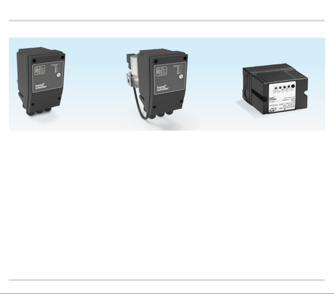
TC 1V, TC 1C
Tightness control TC 1V can be directly flange-mount-
ed to all valVario controls. There is only one version for
all sizes.
TC 1C can be used for combination controls CG 1 to 3.
An adapter plate is supplied for installation.

Application
TC 2 and TC 4
Tightness controls TC 2 and TC 4 can be used with gas
solenoid valves of any nominal size, which are quick
opening or slow opening with start rate. It is possible to
conduct a tightness test on pneumatically operated or
slow opening valves without start rate by using additional auxiliary valves.
Slow opening motorized valves VK up to DN 65 which
are directly flanged together can also be checked by
TC 2 and TC 4 within a temperature range of 0 to 60°C
(32 to 140°F).
An adapter plate is provided for installation of the TC 2.
TC 3
Tightness control TC 3 is a universal device for quick
and slow opening gas solenoid valves of any nominal
size as well as for motorized valves. The tightness test is
carried out with the valves installed in TC 3.
TC 4
Tightness control TC 4 consists of detection circuitry
and can be installed in the control cabinet, separately
from the system. An external pressure switch takes
over the mechanical pressure test between the valves.
Tightness control TC 4 is independent of gas type and
inlet pressure p
and can be used for a test period of up
u
to 10 minutes with a large test volume.
TC · Edition 08.17 5
Application
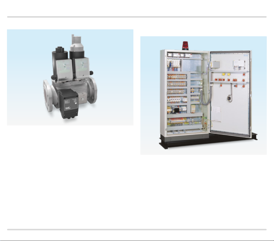
TC 1V on a valVario double solenoid valve TC 4 installed separately from the system in a control
cabinet
TC · Edition 08.17 6
Application
1.1 Application examples
PZ = Internal pressure sensor of the TC for the compari-
son of inlet pressure pu and interspace pressure p
pd = Outlet pressure
V
= Test volume
P
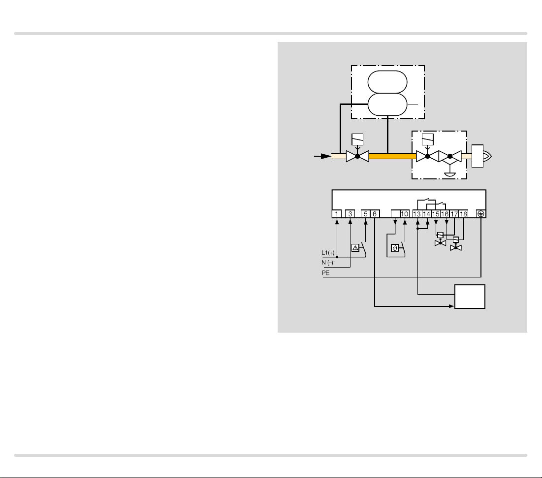
1.1.1 TC 1V with valVario controls
Mains voltage = control voltage
V1: quick or slow opening valve with start rate.
V2: pressure regulator with solenoid valve.
Tightness control TC 1V checks gas solenoid valves V1
and V2 and the pipe between the valves for tightness.
If both valves are tight, the TC forwards the OK enable
signal to the automatic burner control unit GFA. This
opens valves V1 and V2 simultaneously. The burner
starts.
z
p
u
TC 1V
p
PZ
VAS
V1 V2
u
2
VAD
p
z
V
P
TC 1V
9
V1
V2
GFA
OK
TC · Edition 08.17 7
Application
1.1.2 TC 1C with combination control CG..D or CG..V
Mains voltage = control voltage
V1 and V2: quick opening valves.
TC 1C is directly flange-mounted to combination con-
trol CG..D or CG..V and checks gas solenoid valves V1
and V2 in the combination control for tightness.
Once the tightness test has been carried out successfully, the tightness control forwards the OK enable
signal to the automatic burner control unit GFA. This
opens valves V1 and V2 in the combination control CG
simultaneously. The burner starts.
TC 1C
p
PZ
CG
p
PZ
u
V1 V2
u
2
p
z
V
P
TC 1C
9
V1
GFA
OK
TC · Edition 08.17 8
Application
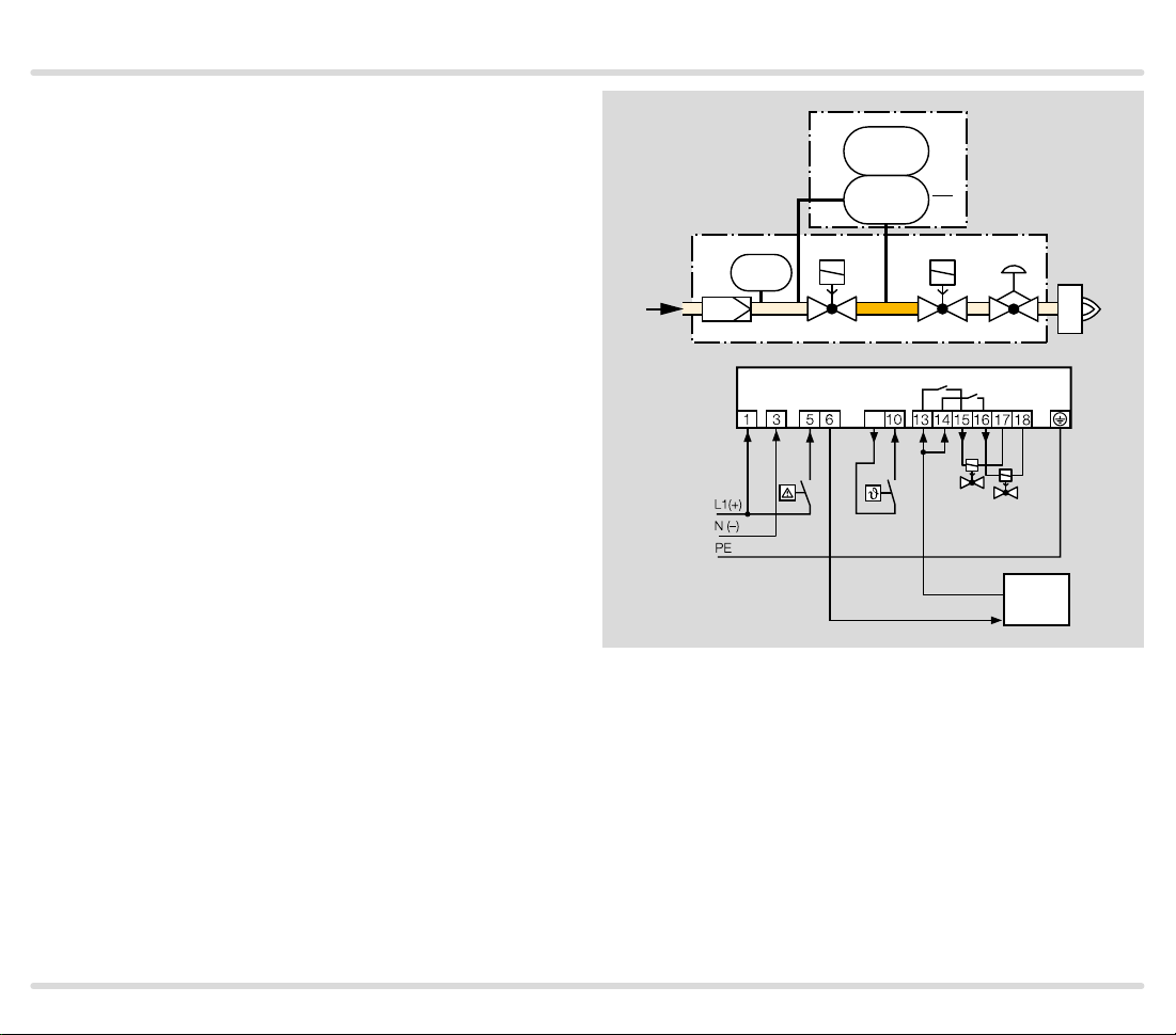
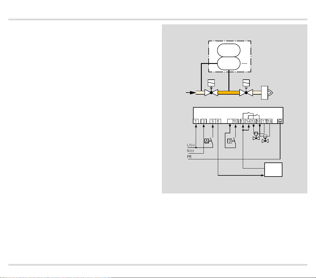
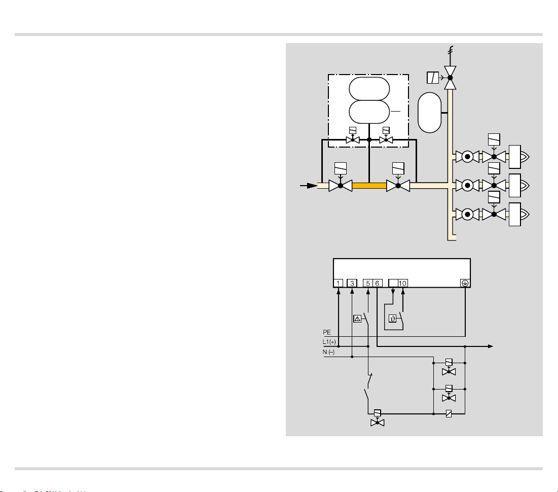
1.1.3 TC 2 with two gas solenoid valves
Mains voltage = control voltage
V1 and V2: quick or slow opening valves with start rate.
TC 2 checks gas solenoid valves V1 and V2 and the pipe
between the valves for tightness.
If both valves are tight, the TC forwards the OK enable
signal to the automatic burner control unit GFA. This
opens valves V1 and V2 simultaneously. The burner
starts.
TC 2
p
PZ
V1 V2
p
u
V
u
2
p
z
P
TC 2
9
V1
V2
GFA
OK
TC · Edition 08.17 9
Application
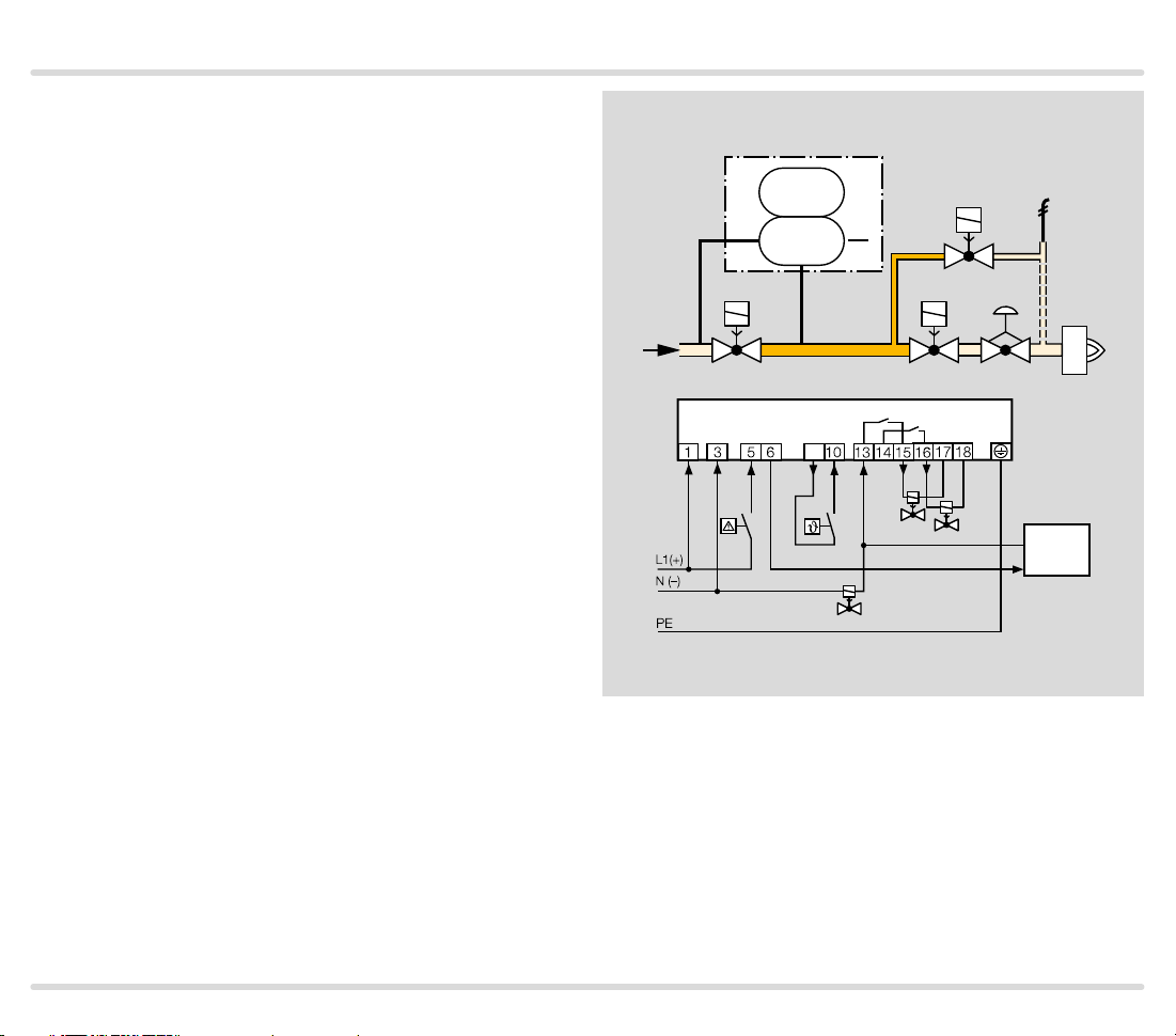
1.1.4
TC 2 with t wo gas solenoid valves and one auxiliar y
valve for discharge
Mains voltage = control voltage
V1 and V2: quick or slow opening valves with start rate.
V3: quick or slow opening valve with start rate, nominal
size is dependent on test volume VP and inlet pressure pu, see page 38 (Project planning information),
but is at least DN 15.
TC 2 checks gas solenoid valves V1, V2, the auxiliary
valve V3 and the pipe between the valves for tightness.
It must be ensured that the interspace p
ing the 3-second opening time. This is not guaranteed
by the gas pressure regulator downstream of V2. A relief
line is thus used to discharge the test volume VP safely
into the combustion chamber or into a safe area. Auxiliary valve V3 can also be used as a pilot gas valve. Since
valve V2 remains closed during the test, it can also be a
slow opening motorized valve VK.
Once the tightness test has been carried out successfully, the tightness control forwards the OK enable signal to the automatic burner control unit GFA. The GFA
opens the gas solenoid valves V1 and V2 simultaneously. The burner starts.
is vented dur-
z
TC 2
p
PZ
V1 V2
p
u
u
2
p
z
V
P
V3
TC 2
9
OK
V1
V3
V2
GFA
TC · Edition 08.17 10
Application
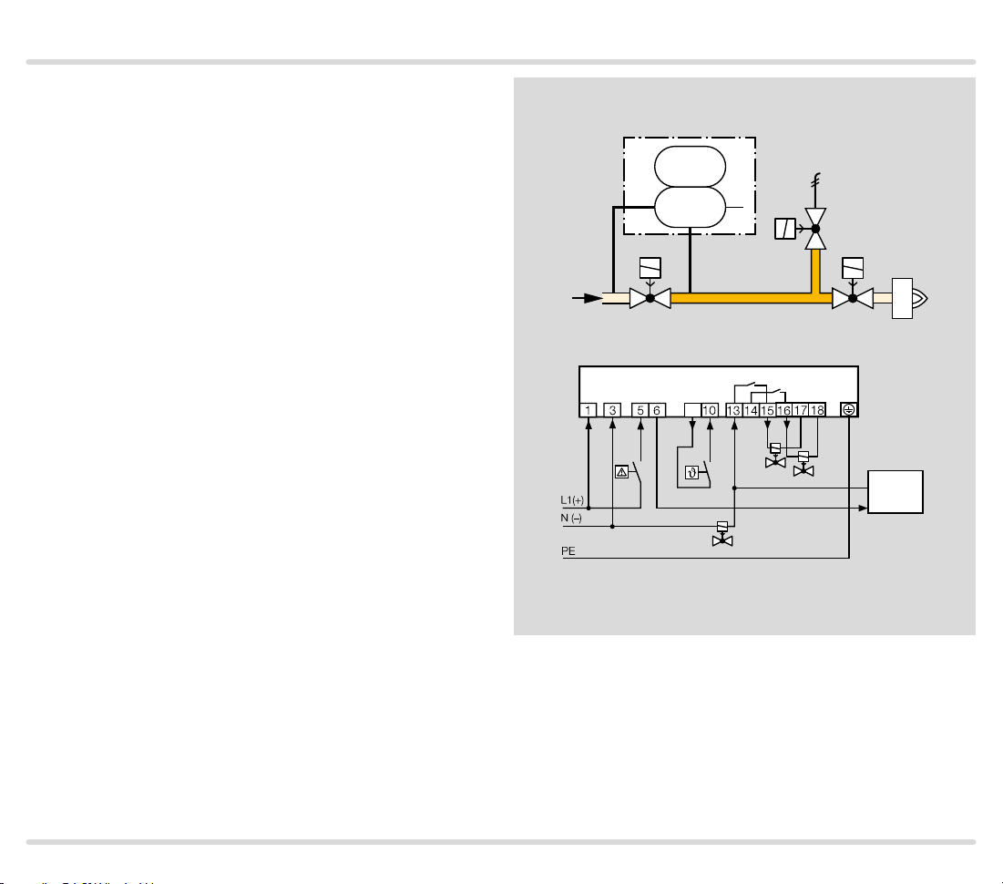
1.1.5
TC 2 with t wo gas solenoid valves and one auxiliar y
valve for discharge
Mains voltage = control voltage
V1: quick or slow opening valve with start rate.
V2: any.
V3: quick opening, nominal size is dependent on test
volume VP and inlet pressure pu, see page 38 (Project planning information), but is at least DN 15.
TC 2 checks gas solenoid valves V1, V2, the auxiliary
valve V3 and the pipe between the valves for tightness.
If all the gas solenoid valves are tight, the tightness
control forwards the OK enable signal to the automatic
burner control unit GFA. The GFA opens the gas solenoid valves V1 and V2 simultaneously. The burner
starts.
A relief line is used to discharge the test volume V
a safe area. Thanks to the installed auxiliary valve V3,
valve V2 can also be a slow opening motorized valve VK.
into
P
TC 2
p
PZ
V1
p
u
u
2
V3
p
z
V
P
V2
TC 2
9
OK
V1
V3
V2
GFA
TC · Edition 08.17 11
Application
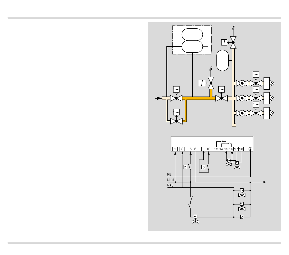
1.1.6
TC 2 in a multiple burner sys tem with several valves
installed in series
Mains voltage = control voltage
V3 and V4: quick opening, nominal size is dependent
on test volume V
(Project planning information), but is at least DN 15.
When using slow opening main valves ( V1 and V2), auxiliary valves (V3 and V4) must be used for the supply
and discharge of the test volume V
TC 2 checks the central shut-off valve V1, the gas so-
lenoid valve V2, the auxiliary valves V3 and V4 and the
pipe between these valves for tightness.
Valve V2 can only be checked for tightness when the
pressure downstream of V2 approximately corresponds
to the atmospheric pressure and the volume downstream of valve V2 is 5 x VP. The gas solenoid valve VAS
and the pressure switch DG
pressure. The pressure switch must be adjusted in such
a way so that enough pressure is relieved and no air can
get into the pipework.
Once the tightness test has been carried out successfully, TC 2 opens the main valves V1 and V2 with the
OK enable signal and enables the downstream burner
control units.
and inlet pressure pu, see page 38
P
.
P
are used to relieve the
VAS
TC 2
p
PZ
V1 V2
p
u
V3
p
z
u
VAS
2
PZ
V4
V
P
VAS
DG
TC 2
9
V3
V4
OK
V2
V1
DG
K1
VAS
VAS
TC · Edition 08.17 12
K1
Application
1.1.7
TC 3 in a multiple burner sy stem with several valves
installed in series
V1 and V2: any.
TC 3 checks slow opening main valves V1 and V2 and
the pipe between these valves for tightness.
The test volume V
TC 3 auxiliary valves.
Valve V2 can only be checked for tightness when the
pressure downstream of V2 approximately corresponds
to the atmospheric pressure and the volume down-
stream of valve V2 is 5 x VP. The gas solenoid valve VAS
and the pressure switch DG
pressure. The pressure switch must be adjusted in such
a way so that enough pressure is relieved and no air can
get into the pipework.
Once the tightness test has been carried out success-
fully, TC 3 opens the main valves V1 and V2 with the
OK enable signal and enables the downstream burner
control units.
is supplied and discharged via the
P
are used to relieve the
VAS
TC 3
p
PZ
2
p
u
V1 V2
p
u
p
z
V
P
VAS
u
PZ
p
d
VAS
DG
TC 3
9
OK
K1
DG
VAS
VAS
TC · Edition 08.17 13
V2
V1
K1
Application
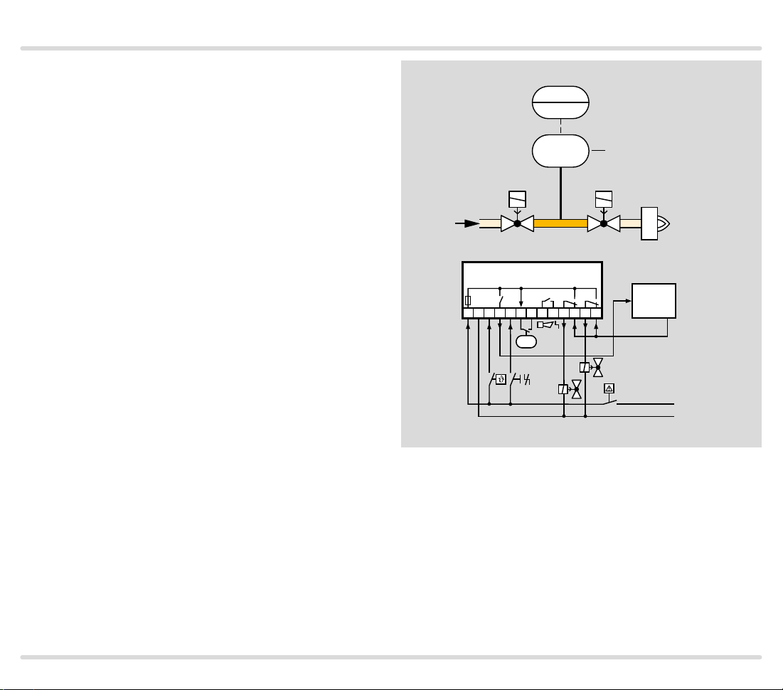
1.1.8 TC 4 with two gas solenoid valves
V1 and V2: quick or slow opening valves with start rate.
TC 4 checks gas solenoid valves V1 and V2 and the pipe
between the valves for tightness.
The external pressure switch DG monitors the pressure
between the two valves.
Once the tightness test has been carried out success-
fully, TC 4 forwards the OK enable signal to the auto-
matic burner control unit GFA. The GFA opens the gas
solenoid valves V1 and V2 simultaneously. The burner
starts.
TC 4
DG
PZ
V1
p
u
p
z
V
P
TC 4
1 2 345 6 7 8 9 10 1112 13
PZ
V2
V1
p
u
2
V2
GFA
OK
L1(+)
N(-)
TC · Edition 08.17 14

Application
1.1.9
TC 4 with t wo gas solenoid valves and one auxiliar y
valve for discharge
V1: quick or slow opening valve with start rate.
V2: any.
V3: quick opening, nominal size is dependent on test
volume VP and inlet pressure pu, see page 38
(Project planning information), but is at least DN 15.
TC 4 checks gas solenoid valves V1, V2, the auxiliary
valve V3 and the pipe between the valves for tightness.
It must be ensured that the interspace p
ing the 2-second opening time. This is not guaranteed
by the gas pressure regulator downstream of V2. A relief
line is thus used to discharge the test volume VP safely
into the combustion chamber or into a safe area. Since
valve V2 remains closed during the test, it can also be a
slow opening motorized valve VK.
If all the gas solenoid valves are tight, TC 4 forwards
the OK enable signal to the automatic burner control
unit GFA. The GFA opens the gas solenoid valves V1
and V2 simultaneously. The burner starts.
is vented dur-
z
TC 4
DG
PZ
V1 V2
p
u
p
z
V
P
TC 4
1 2 345 6 7 8 9 10 1112 13
PZ
V3
ϑ
V1
p
2
V3
u
GFA
OK
V2
L1(+)
N(-)
TC · Edition 08.17 15
Application
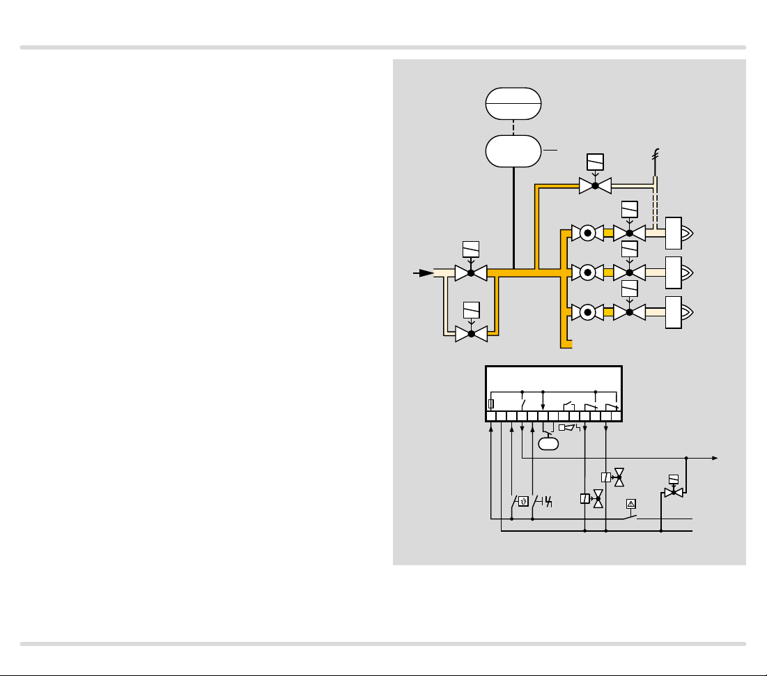
1.1.10
TC 4 in a multiple burner sys tem with two auxil iary
valves for supply and discharge
V1: any.
V2 and V3: quick opening, nominal size is dependent
on test volume VP and inlet pressure pu, see page 38
(Project planning information), but is at least DN 15.
TC 4 checks the central shut-off valve V1, the auxiliary
valves V2 and V3, the burner valves and the pipe be-
tween these valves for tightness.
The test volume V
is supplied via the auxiliary valve V3.
P
The external pressure switch DG monitors the pressure
between the gas solenoid valves V1, V2 and the burner
valves.
Once the tightness test has been carried out success-
fully, TC 4 opens gas solenoid valve V1. The TC forwards
the OK enable signal simultaneously to the automatic
burner control units for the burner valves. The burner
valves open and the burners start.
Thanks to the relief line and auxiliary valve V2, the test
volume VP is discharged into a safe area or into the
combustion chamber.
TC 4
PZ
z
p
u
2
V2
V
P
DG
V1
p
u
p
V3
TC 4
1 2 3 4 5 6 7 8 9 10 1112 13
PZ
V2
V3
OK
V1
L1(+)
N(-)
TC · Edition 08.17 16
Application
1.1.11
TC 4 in a multiple burner sy stem with sever al valves
installed in series
V1 and V2: quick or slow opening valves with start rate.
Tightness control TC 4 checks the central shut-off valve
V1, the gas solenoid valve V2 and the pipe between
these valves for tightness.
Valve V2 can only be checked for tightness when the
pressure downstream of V2 approximately corresponds
to the atmospheric pressure. The gas solenoid valve
VAS and the pressure switch DG
are used to relieve
VAS
the pressure. The pressure switch must be adjusted in
such a way so that enough pressure is relieved and no
air can get into the pipework.
After the thermostat /start-up signal ϑ has been applied,
first DG
is checked. If the pressure downstream of
VAS
V2 is correct, the VAS closes and the tightness test is
started.
Once the tightness test has been carried out success-
fully, TC 4 opens the main valves V1 and V2 with the
OK enable signal and enables the downstream burner
control units.
TC 4
DG
PZ
p
u
2
PZ
V1 V2
p
p
u
z
V
P
VAS
VAS
DG
TC 4
1 2 3 4 5 6 7 8 9 10 1112 13
k1
DG
VAS
VAS
k1
K1
PZ
V2
V1
OK
L1(+)
N(-)
TC · Edition 08.17 17
 Loading...