

62-2016-07
TB7600 Series Communicating
TB7600 Series
Thermostat
TB7600 Series
Thermostat with
Occupancy Sensor
RTU/Heat Pump Thermostats
FOR COMMERCIAL HVAC APPLICATIONS
INSTALLATION INSTRUCTIONS
APPLICATION
The TB7600 Series PI thermostat family is specifically
designed for single stage and multi-stage control of heating/
cooling equipment such as rooftop and self-contained units.
The TB7600 Series are communicating thermostats with
models available in BACnet
mesh protocols and can be easily integrated into a WEBs-AX
building automation system based on the NiagaraAX
platform. The product features an intuitive, menu-driven,
back-lit LCD display, which walks users through the
programming steps, making the process extremely simple.
Accurate temperature control is achieved due to the product’s
PI time proportional control algorithm, which virtually
eliminates temperature offset associated with traditional,
differential-based thermostats.
Depending on the model, up to three remote sensor inputs
are available. All models contain a SPST auxiliary switch,
economizer function and a discharge air sensor input. For more advanced applications, an economizer control logic has
been integrated onto the thermostat for use with proportional damper economizer actuators.
Thermostats equipped with an occupancy sensor cover provide advanced active occupancy logic, which will
automatically switch occupancy levels from Occupied to Unoccupied as required by local activity being present or not.
This advanced occupancy functionality provides advantageous energy savings during occupied hours without
sacrificing occupant comfort. All thermostats are PIR ready and can be ordered with or without Honeywell occupancy
sensor. The occupancy sensor cover is available to order separately if a PIR is needed at a later time.
which can be used to control lighting or disable the
® MS/TP and ZigBee® wireless
®
FEATURES
• Available in BACnet MS/TP and ZigBee wireless protocols
• Backlit LCD display with dedicated function menu keys for simple operation
• Built in default profile set-up for easier start up and commissioning
• Fully integrated advanced occupancy functionality with a PIR accessory cover on some models
• Non-volatile EEPROM memory prevents loss of parameters during power outage
• Programmable smart fan operation can provide energy savings during night mode
• Password protection to minimize parameter tampering
• Three levels of keypad lockout to limit access to change user parameters such as setpoints, system mode,
etc.
• Gas/oil or electric system compatibility for all type of applications
• SPST auxiliary output can be used for lighting and/or economizer override
• 0 to 10 Vdc economizer output for more retrofit oppor tunities
— Built in dry bulb economizer logic using outdoor temperature sensor
— Input for supply/mixed air temperature sensor
• Support single and two stages heat pump with one auxiliary heat stage

TB7600 SERIES COMMUNICATING RTU/HEAT PUMP THERMOSTATS
• Remote indoor averaging sensing with 2, 3, 4, 9 or 16 sensors
• Remote discharge air sensor input
• Automatic frost protection to prevents costly freeze damage
• Anti short cycle and minimum on/off run time protection to reduce wear and maximizes life span of
mechanical equipment
• Two programmable digital inputs for added flexibility can be use to monitor filter status, activate a remote
temporary occupancy switch, and/or used as a general purpose service indicator
• 7 day programmable models, 2 or 4 events for use in non-networked applications*
• Six hour reserve prevents the need to reprogram day/time on programmable models after a power outage
Heat Pump Model Specific Features
• Selectable single or dual stage compressor stages
• High balance point locks out auxiliary heating when outside air temperature is above set value, low balance
point locks out heat pump compressor operation when outside air temperature is below the set value
• Comfort/economy mode maximizes heat pump use before turning on auxiliary heating
• Compressor/auxiliary interlock adds flexibility by locking out heat pump operation during auxiliary heating
to prevent high pressure trip when the coil is downstream of the auxiliary heat source
* Use programmable models only when installing as standalone thermostats that may eventually be added to a WEBs-
AX network. When a programmable thermostat is added to a network, schedules should be applied through the WEBStation-AX.
TB7600 Series Model Selection
Occupancy
Product Number Description Outputs Scheduling
BACnet Models
TB7600A5014B Single Stage RTU 1H/1C No
TB7600A5514B Single Stage RTU 1H/1C No X
TB7600B5014B Multi-stage RTU 2H/2C No
TB7600B5514B Multi-stage RTU 2H/2C No X
TB7600H5014B Heat Pump 3H/2C No
TB7600H5514B Heat Pump 3H/2C No X
TB7605B5014B Economizer RTU 2H/2C No
TB7605B5514B Economizer RTU 2H/2C No X
TB7652A5014B Single Stage RTU 1H/1C Yes
TB7652A5514B Single Stage RTU 1H/1C Yes X
TB7652B5014B Multi-stage RTU 2H/2C Yes
TB7652B5514B Multi-stage RTU 2H/2C Yes X
TB7652H5014B Heat Pump 3H/2C Yes
TB7652H5514B Heat Pump 3H/2C Yes X
TB7656B5014B Economizer RTU 2H/2C Yes
TB7656B5514B Economizer RTU 2H/2C Yes X
Wireless Models
TB7600A5014W Single Stage RTU 1H/1C No
TB7600A5514W Single Stage RTU 1H/1C No X
TB7600B5014W Multi-stage RTU 2H/2C No
TB7600B5514W Multi-stage RTU 2H/2C No X
TB7600H5014W Heat Pump 3H/2C No
TB7600H5514W Heat Pump 3H/2C No X
TB7605B5014W Economizer RTU 2H/2C No
TB7605B5514W Economizer RTU 2H/2C No X
TB7652A5014W Single Stage RTU 1H/1C Yes
TB7652A5514W Single Stage RTU 1H/1C Yes X
1
Sensor
2
62-2016—07 2
TB7600 SERIES COMMUNICATING RTU/HEAT PUMP THERMOSTATS
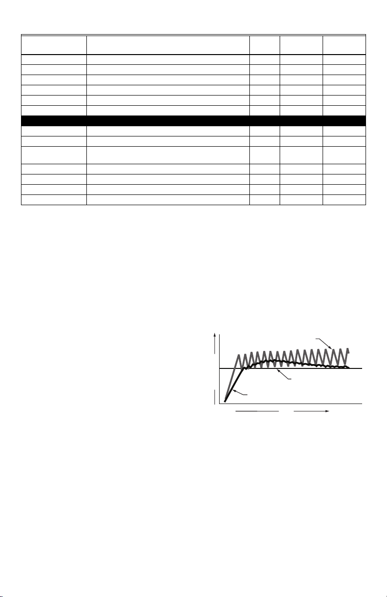
ON/OFF THERMOSTATS WASTE ENERGY
SETPOINT
(COMFORT TEMPERATURE)
TIME
PI ELECTRONIC CONTROLS DO NOT WASTE ENERGY
TEMPERATURE
M16927
Fig. 1. On/Off mechanical control vs.
PI electronic control.
Product Number Description Outputs Scheduling
1
Sensor
2
Occupancy
TB7652B5014W Multi-stage RTU 2H/2C Yes
TB7652B5514W Multi-stage RTU 2H/2C Yes X
TB7652H5014W Heat Pump 3H/2C Yes
TB7652H5514W Heat Pump 3H/2C Yes X
TB7656B5014W Economizer RTU 2H/2C Yes
TB7656B5514W Economizer RTU 2H/2C Yes X
Accessories
TB-PIR-RTU RTU Occupancy Sensor Cover
TB-RA-1014 Wireless Remote Antenna Base
TB-RP5000W Wireless Repeater for TB7XXX Series Wireless
Thermostats
TBST-5014W ZigBee Wireless Survey Toolkit
TB-VWG-APP-1014 TB7XXX Series Wireless Communication Card
TB-WALL-1014 Room Sensor 10K NTC Type 2
TB-WALLOVR-1014 Room Sensor with Override 10K NTC Type 2
1Use programmable models only when installing as standalone thermostats that may eventually be added to a WEBs-
AX network. When a programmable thermostat is added to a network, schedules should be applied through the WEBStation-AX.
2Thermostats ordered without an occupancy sensor cover can be retrofitted with an occupancy sensor cover later if
needed.
More Information
We recommend downloading the appropriate integration reference document (wireless or BACnet) and if installing
thermostats with occupancy sensor covers, then also downloading the PIR Application Guide before you begin
installation. All documentation is available on http://customer.honeywell.com.
— BACnet Integration Manual for TB7600 Series Thermostats (Form No. 63-4523)
— Wireless Installation & Integration Reference Guide for TB7200, TB7300, and TB7600 Thermostats
(Form No. 63-4522)
— PIR Application Guide for TB7600 Series Thermostats (Form No. 63-4525)
— Sensors Product Overview Brochure (Form No. 63-9285) for a complete listing of compatible sensors.
Theory of Operation
The TB7600 uses a proprietary adaptive logic algorithm to
control the space temperature. This algorithm controls the
heating/air conditioning system to minimize overshoot while still
providing comfort. It provides exceptional accuracy due to its
unique PI time proportioning control algorithm, which virtually
eliminates temperature offset associated with traditional,
differential-based on/off thermostats.
INSTALLATION AND WIRING
Mounting Locations
• Do not install on an outside wall.
• Must be installed away from any heat source.
• Should not be installed near an air discharge grill.
• Should not be mounted in direct sun radiation.
• Nothing must restrain vertical air circulation to the thermostat.
• Wall surface must be flat and clean.
IMPORTANT
• If replacing an old thermostat, label the wires before removal of the old thermostat.
3 62-2016—07
TB7600 SERIES COMMUNICATING RTU/HEAT PUMP THERMOSTATS
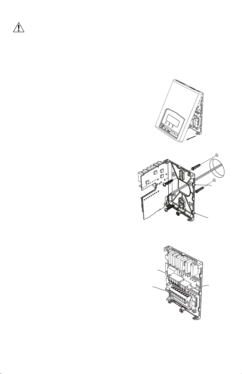
CAUTION
°C
°F
M21300
Fig. 2. Remove cover of thermostat
PCB
RETAINING
TABS
PCB
RETAINING
TABS
M21301
Fig. 3. Location of PCB retaining tabs and
mounting screws
Fig. 4. Terminal blocks
Electronic controls are static sensitive devices. Discharge yourself properly before manipulation and installing
the thermostat.
Short circuit or wrong wiring may permanently damage the thermostat or the equipment.
Anti-short cycling can be set to 0 minutes for equipment that has an anti-cycling timer. Do not set to 0 unless the
equipment has an internal anti-cycling timer or damage to equipment can occur.
All TB7600 Series thermostats are to be used only as operating controls. Whenever a control failure could lead
to personal injury and/or loss of property, it becomes the responsibility of the user to add safety devices and/
or alarm system to protect against such catastrophic failures.
Thermostat Installation
1. Open up by pulling on the bottom side of thermostat.
(Fig. 2)
2. Remove wiring terminals.
3. Open the thermostat PCB to the left by pressing the PCB
retaining tabs. (Fig. 3).
4. Pull cables 6 inches out of the wall.
5. Thread cable through the central hole of the base.
6. Align the base and mark the location of the two mounting
holes on the wall. Install proper side of base up.
7. Install anchors in the wall.
8. Insert screws through the mounting holes on each side of
the base and mount base on wall. (Fig. 3).
9. Gently swing back the circuit board back to the base and
push on it until the tabs lock it in place.
10. Strip each wire 1/4 inch.
11. Wire the terminals. See Table 1 for terminal descriptions
and wiring diagram.
12. Gently push back excess cable into hole.
13. Install wiring terminals in correct location (Fig. 4).
14. Reinstall the cover (top first).
15. Install security screw on the bottom, center of the thermo-
stat cover.
62-2016—07 4
TOP LEFT
5 POLE
CONNECTOR
BOTTOM
8 POLE
CONNECTOR
TOP RIGHT
3 POLE
CONNECTOR
M21302
TB7600 SERIES COMMUNICATING RTU/HEAT PUMP THERMOSTATS
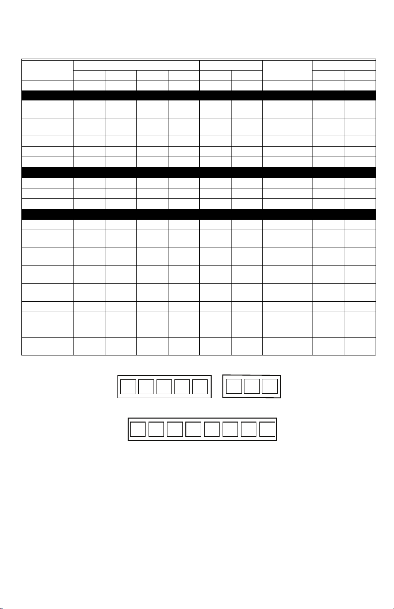
Wiring Identification and Screw Terminal Arrangement
Tab l e 1. Terminal identification
Multistage 1H/1C
Model Number
TB7656B TB7605B TB7652B TB7600B TB7652A TB7600A TB7652H TB7600H
Model Number
Programmable Yes No Yes No Yes No Programmable Yes No
Top left terminal block
1- Cool Stage 2 Y2 Y2 Y2 Y2 Blank Blank 1- Compressor
2- Cool Stage 1Y1Y1Y1Y1Y1Y12- Compressor
Stage 2
Stage 1
3- Fan GGGGGG3- Fan GG
4- 24 V - HotRCRCRCRCRCRC4- 24 V - HotRCRC
5- 24 V - ComCCCCCC5- 24 V - ComCC
Top right terminal block
6- RH RH RH RH RH RH RH 6- RH RH RH
7- Heat Stage 1 W1 W1 W1 W1 W1 W1 7- AUX Heat W1 W1
8- Heat Stage 2 W2 W2 W2 W2 Blank Blank 8- O/B O/B O/B
Bottom terminal block
9- Econo EC EC Blank Blank Blank Blank 9- Not Used Blank Blank
10- Auxiliary
Output
AuxAuxAuxAuxAuxAux10- Auxiliary
Output
11- Digital Input 1DI1 DI1 D I1 DI1 DI1 DI1 11 - Digital Input 1DI1 DI1
12- Digital Input 2DI2 DI2 D I2 DI2 DI2 DI2 12 - Digital Input 2DI2 DI2
Heat Pump
Y2 Y2
Y1 Y1
Aux Aux
13- Remote
Sensor
RS RS RS RS RS RS 13- Remote
Sensor
RS RS
14- Scom S COM S COM S COM S COM S COM S COM 14- Scom S COM S COM
15- Remote
Outdoor
Sensor
16- Mixed Air
Sensor
OS OS OS OS OS OS 15- Remote
MS MS MS MS MS MS 16- Mixed Air
5 POLE LEFT TOP CONNECTOR
Y1
Y2
EC
G
AU
RC
8 POLE BOTOM CONNECTOR
D1 D2
3 POLE LEFT TOP CONNECTOR
C
RS
Scom
RH W1
OS
Outdoor
Sensor
Sensor
W2
O/B
MS
M16928
OS OS
MS MS
Fig. 5. Screw terminal arrangement
NOTES:
— If auxiliary output is used to toggle occupancy of the electronic control card inside the equipment, configure
the relay parameter (Aux cont) to the N.O. setting. A second relay can be added for additional functionality
of the occupancy output.
— If the same power source is used for the heating stages, install jumper across RC and RH. Maximum cur-
rent is 2.0 amps.
— Economizer output uses a half bridge rectifier. Reference of the control signal is the common of the power
supply of the thermostat (terminal C).
— Electromechanical contacts are to be used with the digital inputs. Electronic triacs cannot be used as mean
of switching for the input. The switched leg to the input for the input to activate is terminal C (common).
— The transformer of the unit provides power to the thermostat and the additional loads that will be wired to
the thermostat.
5 62-2016—07
TB7600 SERIES COMMUNICATING RTU/HEAT PUMP THERMOSTATS
Y2
Y1
G
RC
C
RH
W1
JUMPER
J1
COOL
STAGE 2
COOL
STAGE 1
FAN
HEAT
STAGE 1
HEAT
STAGE 2
0-10 VDC
24V
COM
AUXILIARY
OUTPUT
W2
EC
AU
DI1
DI2
DIGITAL INPUT #1
DIGITAL INPUT #2
RS
Scom
OS
MS
REMOTE
MIXED AIR
SENSOR
REMOTE
OUTDOOR
SENSOR
REMOTE
ROOM
SENSOR
FIELD CONTACTS
THERMOSTAT
INTERNAL WIRING
SYSTEM WIRING
M16929
24 VAC
T1
ECONOMIZER
ACTUATOR
Y2
Y1
G
RC
C
RH
W1
JUMPER
J1
COMPRESSOR
STAGE 2
COMPRESSOR
STAGE 1
FAN
AUXILIARY
HEAT
REVERSING
VALV E
AUXILIARY
OUTPUT
O/B
AU
DI1
DI2
DIGITAL INPUT #1
DIGITAL INPUT #2
RS
Scom
OS
MS
REMOTE
MIXED AIR
SENSOR
REMOTE
OUTDOOR
SENSOR
REMOTE
ROOM
SENSOR
THERMOSTAT INTERNAL WIRING
SYSTEM WIRING
24 VAC
T1
FIELD CONTACTS
M16930
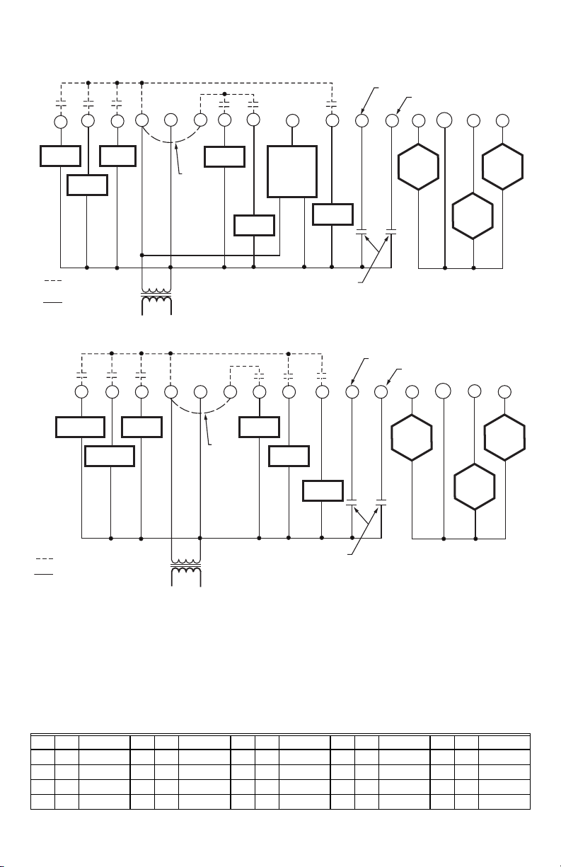
Detailed Wiring Diagrams for Selected Models
Fig. 6. TB7656B5x00(x) 2 Heat/2 Cool/Economizer/Programmable
Fig. 7. TB7652H5x00(x) Heat pump/Programmable
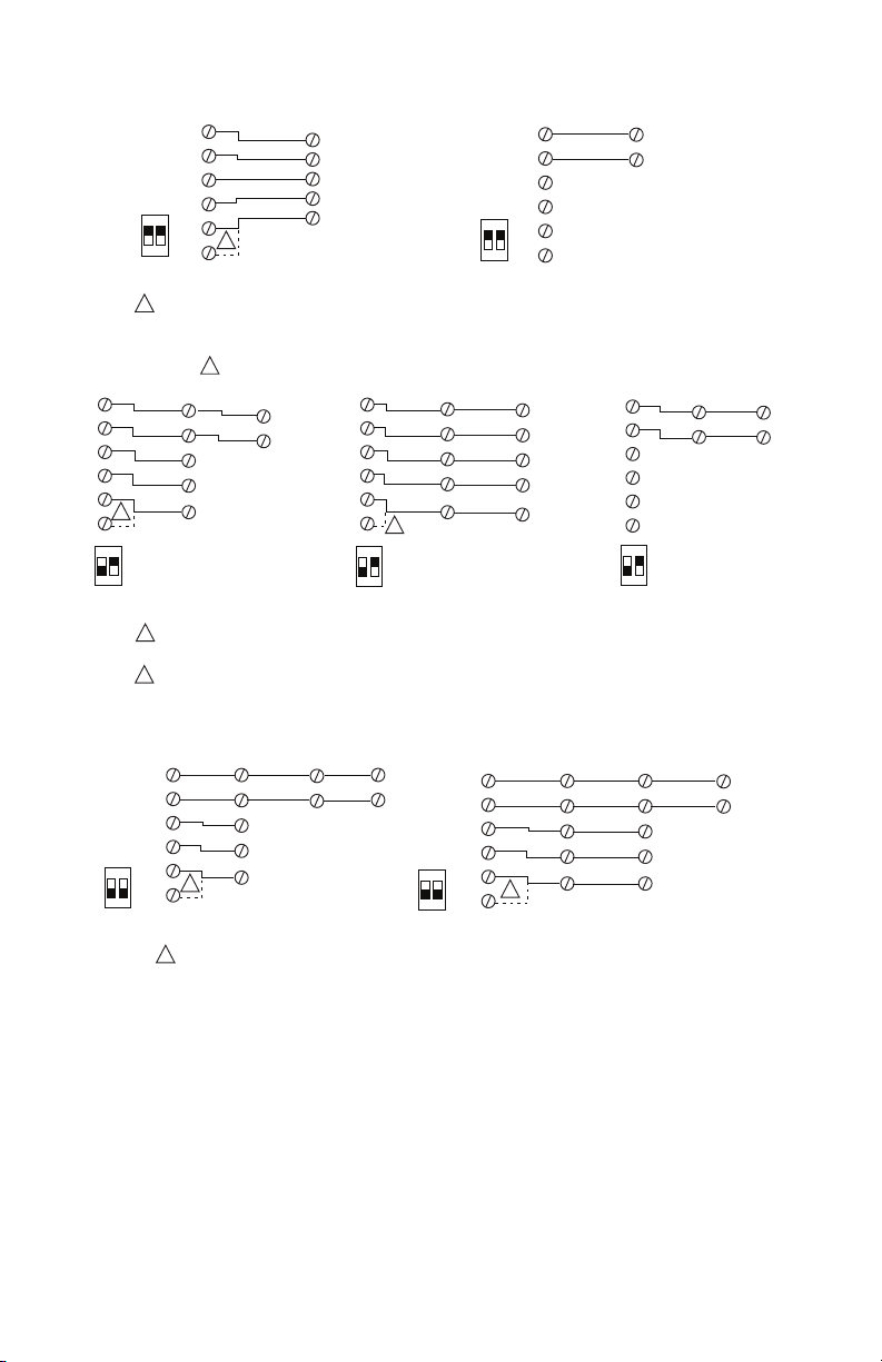
Sensor Wiring for all Thermostat Models
Remote mount outdoor temperature sensors must be10 Kohm NTC @ 77 F.
Remote sensors can be used for:
• Various averaging combinations (3 thermistors with 2 dip switches are provided with each sensor)
• Optional occupancy led
• Optional override key
Table 2. Temperature vs. Resistance for 10 Kohm NTC thermistor (R
ºF ºC Kohm ºF ºC Kohm ºF ºC Kohm ºF ºC Kohm ºF ºC Kohm
-40 -40 324.3197 -4 -20 94.5149 32 0 32.1910 68 20 12.4601 104 40 5.3467
-31 -35 234.4009 5 -15 71.2430 41 5 25.1119 77 25 10.0000 113 45 4.3881
-22 -30 171.3474 14 -10 54.1988 50 10 19.7390 86 30 8.0694 122 50 3.6202
= 10KW±3%, B
25°C
25/85°C
-13 -25 126.6109 23 -5 41.5956 59 15 15.6286 95 35 6.5499 131 55 3.0016
62-2016—07 6
= 3975K±1.5%)
TB7600 SERIES COMMUNICATING RTU/HEAT PUMP THERMOSTATS
Scom
RS
AU
C
D1
Scom
RS
AUX
C
DI
Scom
RS
TB7600 SERIES
THERMOSTAT
TB7600 SERIES
THERMOSTAT
TB-WALLOVR-1014 TB-WALL-1014
DIP SWITCHES
S1 = ON S2 = ON
DIP SWITCHES
S2-1 = ON S2-2 = ON
ON
12
S2
DIP SWITCHES
S2-1 = ON S2-2 = ON
ON
12
S2
REMOTE WIRING 1 SENSOR
M16996
DIP SWITCHES
S1 = ON S2 = ON
D2
Scom
RS
AU
C
D1
D2
EITHER D1 OR D2 CAN BE USED ON THE TB7600 FOR CONNECTION FROM THE DI ON THE WALL MODULE WITH OVERRIDE.
1
1
Fig. 8. Wiring example of single remote wall mounted room sensor
REMOTE WIRING 2 SENSORS
TB7600 SERIES
THERMOSTAT
Scom
RS
AU
C
D1
2
D2
S2
ON
12
DIP SWITCHES
S2-1 = OFF
S2-2 = ON
1
Scom
AUX
TB-WALL-1014
RS
DIP SWITCHES
S1 = OFF
S2 = ON
C
DI
TB-WALLOVR-1014 TB-WALL-1014
DIP SWITCHES
S1 = OFF
S2 = ON
TB-WALL-1014 AND TB-WALLOVR-1014 CAN BE MIXED AND MATCHED
1
TB-WALL-1014 AND TB-WALLOVR-1014 ARE TO BE WIRED IN PARALLELL
ENSURE THE DIP SWITCH SETTING IS CORRECT IN EACH REMOTE SENSOR
EITHER D1 OR D2 CAN BE USED ON THE TB7600 FOR CONNECTION FROM THE DI ON THE WALL MODULE WITH OVERRIDE.
2
Scom
RS
TB7600 SERIES
THERMOSTAT
Scom
RS
AU
C
D1
D2
S2
ON
12
DIP SWITCHES
S2-1 = OFF
S2-2 = ON
TB-WALLOVR-1014
Scom
RS
AUX
C
DI
2
DIP SWITCHES
S1 = OFF
S2 = ON
TB-WALLOVR-1014
Scom
RS
AUX
C
DI
DIP SWITCHES
S1 = OFF
S2 = ON
TB7600 SERIES
THERMOSTAT
Scom
RS
AU
C
D1
D2
S2
ON
12
DIP SWITCHES
S2-1 = OFF
S2-2 = ON
Scom
RS
DIP SWITCHES
S1 = OFF
S2 = ON
M16997A
Fig. 9. Wiring examples of two remote wall mounted room sensors for averaging applications
REMOTE WIRING 3 SENSORS
TB7600 SERIES
THERMOSTAT
Scom
RS
AU
C
S2
D1
ON
12
DIP SWITCHES
S2-1 = OFF
S2-2 = OFF
1
D2
EITHER D1 OR D2 CAN BE USED ON THE TB7600 FOR CONNECTION FROM THE DI ON THE WALL MODULE WITH OVERRIDE.
1
TB-WALLOVR-1014
Scom
RS
AUX
C
DI
DIP SWITCHES
S1 = OFF
S2 = OFF
TB-WALL-1014
Scom
RS
DIP SWITCHES
S1 = OFF
S2 = OFF
TB-WALL-1014
Scom
RS
S2
DIP SWITCHES
S2-1 = OFF
S2-2 = OFF
TB7600 SERIES
THERMOSTAT
ON
12
Scom
RS
AU
C
D1
D2
TB-WALLOVR-1014
Scom
1
RS
AUX
C
DI
DIP SWITCHES
S1 = OFF
S2 = OFF
TB-WALLOVR-1014
Scom
RS
AUX
C
DI
TB-WALL-1014
DIP SWITCHES
S1 = OFF
S2 = OFF
Fig. 10. Wiring examples of three remote wall mounted room sensors for averaging applications
TB-WALL-1014
DIP SWITCHES
S1 = OFF
S2 = ON
Scom
RS
M16998
Scom
RS
7 62-2016—07
TB7600 SERIES COMMUNICATING RTU/HEAT PUMP THERMOSTATS
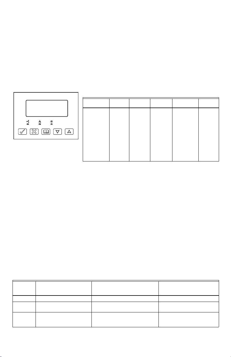
Fig. 11. Heat pump, multistage
and single stage models buttons
and display
THERMOSTAT USER INTERFACE
The thermostat features a two-line, eight-character display. There is a low-level backlit level that is always active and
can only be seen at night. To turn on the back light to high level, press any key on the front panel. The back lit display
will return to low level when the thermostat is left unattended for 45 seconds.
When left unattended, the thermostat has an auto scrolling display that shows the actual status of the system. Use the
MenuScro in the configuration menu to lockout the scrolling display and to only present the room temperature and
conditional outdoor temperature to the user. With this option enabled, no local status is given on the system mode or
occupancy.
Each item is scrolled one by one with the back lighting in low level mode. Pressing any key will cause the back light to
come on to high level. When left unattended for 10 seconds after changes are made, the display will resume automatic
status display scrolling.
Table 3. Sequence and possible display options
Room Temp
RoomTemp
x.x °C or°F
YES NO MENU
Manual scroll of each menu item is achieved by pressing the Ye s (scroll) key repetitively. The last item viewed will be
shown on the display for 30 seconds before returning to automatic scrolling. Temperature is automatically updated
when scrolling is held.
Outdoor air temperature display is only enabled when outdoor air temperature sensor is connected.
• A maximum range status display of 122 F (50 C) indicates a shorted sensor. Associated functions, such as mode
lockouts and economizer function are automatically disabled.
• A minimum range status -40 F (-40 C) is not displayed and indicates a opened sensor or a sensor not connected.
Associated functions, such as mode lockouts and economizer function are automatically disabled.
If alarms are detected, they will automatically be displayed at the end of the status display scroll. During an alar m
message display, the back lit screen will light up at the same time as the message and shut off during the rest of the
status display. Two alarms maximum can appear at any given time. The priority for the alarms is as follows:
• Frost ON: Indicates that the heating is energized by the low limit frost protection room temperature setpoint 42 F
(5.6 C)
• SetClock: Indicates that the clock needs to be reset. There has been a power failure which has lasted longer than 6
hours
• Service: Indicates that there is a service alarm as per one of the programmable digital input (DI1 or DI2)
• Filter: Indicates that the filters are dir ty as per one of the programmable digital input (DI1 or DI2)
• Fan lock: Indicates that the heating and cooling action are locked out due to a defective fan operation
Three status LEDs on the thermostat cover are used to indicate the status of the fan, a call for heat, or a call for cooling.
See Table 4 for more details.
LED
operation
Fan LED on When G Fan terminal operates When G Fan terminal operates When G Fan terminal operates
Heating
LED on
Cooling
LED on
Heat pump models
When Y1 and/or W1 terminal(s)
operate in heating mode
When Y1 terminal operate in
cooling mode
M16916
*Network value only
TB76xxH
>
Table 4. LED Status
Multistage and single stage models
TB7600A, TB7652A, TB7600B and
When W1 terminal operate in heating
mode
When Y1 terminal operate in cooling
mode
for the auto-scroll display
Clock
status
Monday
12.00 AM
>
Sys mode
auto
Sys mode
off
Sys mode
heat
Sys mode
cool
Sys mode
emergenc
TB7652B
System
mode
Schedule
>
status
Occupied Outdoor
Occupied
hold
Unoccup SetClock
Unoccup
hold
Override Fan lock
Outdoor
>
x.x °C or°F
Multistage economizer models
TB7605B and TB7656B
When W1 terminal operate in
heating mode
When Y1 terminal operate in
cooling mode and or economizer
output is in function
Tem p*
>
Service
Frost ON
Filter
Alarms
62-2016—07 8
TB7600 SERIES COMMUNICATING RTU/HEAT PUMP THERMOSTATS
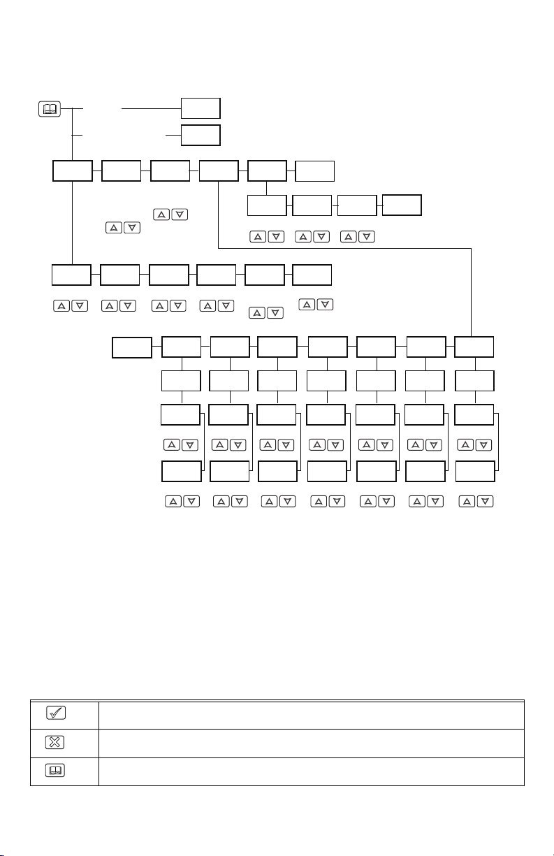
User menu flow chart
NOTE: Prompts may not all be present depending on model selected
FAN MODE
SET? Y/N
ON
SMART
AUTO
UNOCC CL
SET? Y/N
SUNDAY
SET? Y/N
OCCUPIED
DAY? Y/N
OCCUPIED
12:00 PM
UNOCCUP
12:00 PM
TIME
TIME
OVERRIDE
SCHD Y/N
CANCEL
OVRD Y/N
UNOCC HT
SET? Y/N
SCHEDULE
SET? Y/N
SATURDAY
SET? Y/N
OCCUPIED
DAY? Y/N
OCCUPIED
12:00 PM
TIME
UNOCCUP
12:00 PM
TIME
IF STATUS IS:
UNOCCUPIED
IF STATUS IS:
TEMPORARY OCCUPIED TIME
TEMPERAT
SET? Y/N
COOLING
SET? Y/N
TEMPERATURE TEMPERATURE TEMPERATURE TEMPERATURE
SYS MODE
SET? Y/N
OFF
EMERGENC
HEAT
COOL
AUTO
HEATING
SET? Y/N
EXIT
Y/N
CLOCK
SET? Y/N
TIME
SET? Y/N
°F/°C
SET? Y/N
EXIT
MENU Y/N
DAY
SET? Y/N
TIME DAY 12/24
EXIT
Y/N
°C
°F
FRIDAY
SET? Y/N
OCCUPIED
DAY? Y/N
OCCUPIED
12:00 PM
TIME
UNOCCUP
12:00 PM
TIME
THURSDAY
SET? Y/N
OCCUPIED
DAY? Y/N
OCCUPIED
12:00 PM
TIME
UNOCCUP
12:00 PM
TIME
12/24 HRS
SET? Y/N
WEDNESDA
SET? Y/N
OCCUPIED
DAY? Y/N
OCCUPIED
12:00 PM
TIME
UNOCCUP
12:00 PM
TIME
EXIT
Y/N
TUESDAY
SET? Y/N
OCCUPIED
DAY? Y/N
OCCUPIED
12:00 PM
TIME
UNOCCUP
12:00 PM
TIME
MONDAY
SET? Y/N
OCCUPIED
DAY? Y/N
OCCUPIED
12:00 PM
TIME
UNOCCUP
12:00 PM
TIME
M16931
User Control Options
The TB7600 Series thermostat features an intuitive, menu-driven, back-lit LCD display that walks users through the
programming steps, making the programming process extremely simple. This menu is typically accessed by the user to
modify system setting such as temperature or system mode, fan mode, etc.
It is possible to bring up the user menu at any time by pressing the MENU key. The status display automatically
resumes after exiting the user-programming menu.
If the user pauses at any given time during programming, Auto Help text is displayed to help and guide the user
through the usage and programming of the thermostat. When left unattended for 45 seconds, the display will resume
automatic status display scrolling.
User options are accessed and programmed using 5 keys on the thermostat cover and are described in Table 5.
Table 5. User Control with Thermostat Keys
The YES key is used to confirm a selection, to move onto the next menu item and to manually scroll
M16911
M16912
M16913
through the displayed information.
The NO key is used when you do not desire a parameter change, and to advance to the next menu
item. Can also be used to toggle between heating and cooling setpoints.
The MENU key is used to access the Main User Menu or exit the menu.
9 62-2016—07
 Loading...