

Honeywell T834B, T834C, T834J Installation Instructions Manual
T834B; T834C; T834J
Heating-Cooling Thermostats
INSTALLATION INSTRUCTIONS
APPLICATION
The T834B,C,J Heating-Cooling Thermostats provide 24
to 30 Vac control in heating-cooling systems. An spdt
mercury switch makes R to W on a temperature fall for
heating, and R to Y on a temperature rise for cooling.
Integral switches control HEAT-OFF-COOL or COOL-OFF
system operation and AUTO-ON or ON-AUTO fan
operation (fan switch on T834C,J only). In heat pump and
some electric heat systems, fan operation is controlled by
the thermostat during heating. Check the electric heat
manufacturer specifications for fan control requirements. If
fan control from the thermostat is necessary in an electric
heat application, use the T834C Thermostat model (dual
fuel) with optional fan control. Jumper terminals 1 and 2 to
control fan operation from the thermostat during heating.
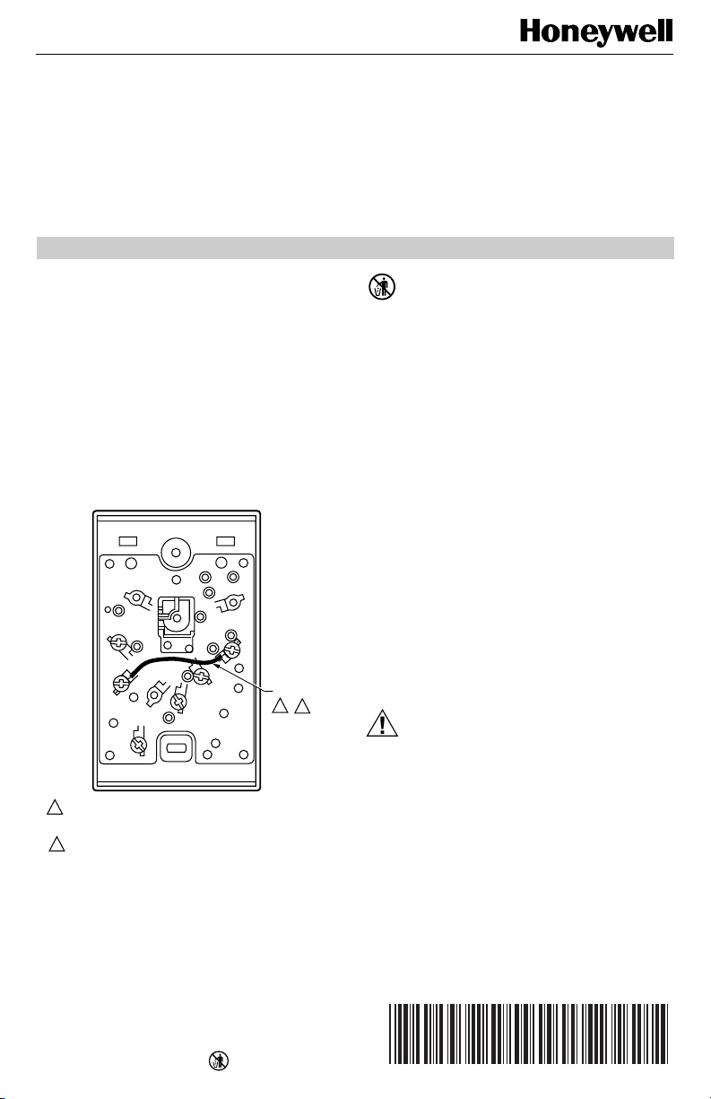
R
2
1
W
IN ELECTRIC HEAT AND HEAT PUMP APPLICATIONS, JUMPER
1
TERMINALS 1 AND 2 FOR AUTOMATIC FAN CONTROL IN HEATING
AND COOLING.
2
IN GAS-AND OIL-FIRED APPLICATIONS, JUMPER TERMINALS 1
AND Y FOR AUTOMATIC FAN CONTROL IN COOLING.
Fig. 1. Jumpering terminals for fan control.
G
Y
JUMPER
1
2
M8675
RECYCLING NOTICE
This control contains mercury in a sealed tube.
Do not place control in the trash at the end of
its useful life.
If this control is replacing a control that contains
mercury in a sealed tube, do not place your old
control in the trash.
Contact your local waste management authority
for instructions regarding recycling and the proper
disposal of this control, or of an old control
containing mercury in a sealed tube.
INSTALLATION
When Installing this Product…
1. Read these instructions carefully. Failure to follow
them could damage the product or cause a hazardous condition.
2. Check the ratings given in the instructions and on
the product to make sure the product is suitable for
your application.
3. Installer must be a trained, experienced service
technician.
4. After installation is complete, check out product
operation as provided in these instructions.
CAUTION
Damage to Heating/Cooling System Possible.
Be careful when handling wires during
installation.
Disconnect power at furnace or at main breaker/
fuse before starting installation.
Location
Locate the thermostat about 5 ft (1.5m) above the floor on
an inside wall in an area with good air circulation at
average temperature.
Do not mount the thermostat where it may be affected by:
— drafts or dead spots behind doors or in corners.
— hot or cold air from ducts.
— radiant heat from the sun, fireplaces, or appliances.
®U.S. Registered Trademark
Copyright © 1999 Honeywell Inc. • • All Rights Reserved
X-XX UL
69-0444-10
T834B; T834C; T834J HEATING-COOLING THERMOSTATS
Wiring and Mounting
Disconnect power supply before beginning installation to
prevent electrical shock or equipment damage.
All wiring must comply with local codes and ordinances.
The T834 may be mounted directly on a wall or vertical
outlet box. Use Honeywell part no. 193121A Mounting
Plate Assembly (ordered separately) to mount on horizontal outlet box or cover marks left by old thermostat. If
mounting plate assembly is used, review instructions
provided with assembly before wiring and mounting
thermostat.
To wire and mount thermostat:
1. In replacement applications, check the existing
thermostat wires for cracked or frayed insulation.
Replace any wires in poor condition. If the wire is
plastered into the wall, make a hole next to the
wires and loosen the wires so they can be
pushed back into the wall later.
2. In new installations, run wiring (if necessary) to the
thermostat location.
3. Connect the wires to the terminals on the back of
the thermostat. See Fig. 3 through 12 for
internal schematic and typical hookup diagrams.
If control of fan operation from the thermostat is
required in a central electric heat application,
jumper terminals 1 and 2. See Fig. 1.
4. Remove thermostat cover by pulling outward on
bottom edge of the cover until it snaps free of the
thermostat base. See Fig. 2. Carefully remove
and discard the foam plastic shipping insert that
protects the switch and bimetal assembly during
shipping.
5. Set the adjustable heat anticipator indicator to
match the current draw of the primary heating
control (see Heat Anticipator Setting section).
6. Push excess wire back through the hole and plug
any opening with insulation to prevent drafts that
may affect thermostat performance.
7. Loosely fasten the thermostat to the wall or outlet
box with a screw through the top mounting hole.
Adjust the thermostat so that it is approximately
level and start the second screw through the
bottom mounting hole. Do not tighten.
8. Level the thermostat exactly using a spirit level or
plumb line. Tighten the mounting screws.
IMPORTANT
An incorrectly leveled thermostat will cause the
temperature control to deviate from setpoint.
9. Replace the thermostat cover.
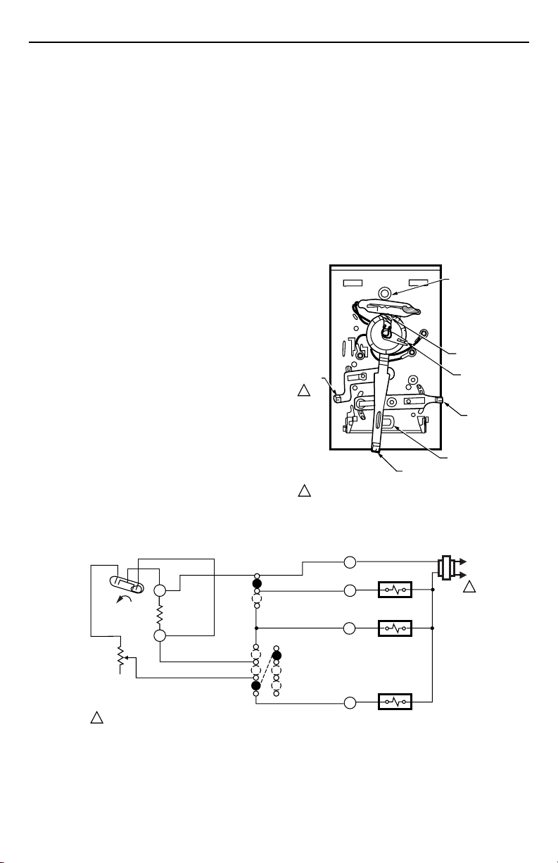
MOUNTING HOLE
(THERMOSTAT
TO WALL OR
OUTLET BOX)
.18
.9
.7
.2
.5
3
.25
FAN
SWITCH
1
TEMPERATURE
1 FAN SWITCH AVAILABLE ON T834C ONLY.
SETTING LEVER
BIMETAL ELEMENT
BEHIND SCALE
ADJUSTABLE HEAT
ANTICIPATOR
INDICATOR
SYSTEM
SWITCH
MOUNTING HOLE
Fig. 2. Internal view of T834.
M8676
FAN SWITCH
H1
H1
ANTICIPATOR
1
C1
TEMP. FALL
POWER SUPPLY. PROVIDE DISCONNECT MEANS AND OVERLOAD PROTECTION AS REQUIRED.
C1
ANTICIPATOR
AUTO
SYSTEM
SWITCH
COOL
OFF
HEAT
ON
HEAT
OFF
COOL
R
G
Y
W
FAN RELAY
COMPRESSOR
CONTACTOR
HEAT RELAY
Fig. 3. Internal schematic and typical hookup diagram for T834C in standard heating-cooling system.
69-0444—10 2
M1119A
L1
(HOT)
L2
1
T834B; T834C; T834J HEATING-COOLING THERMOSTATS
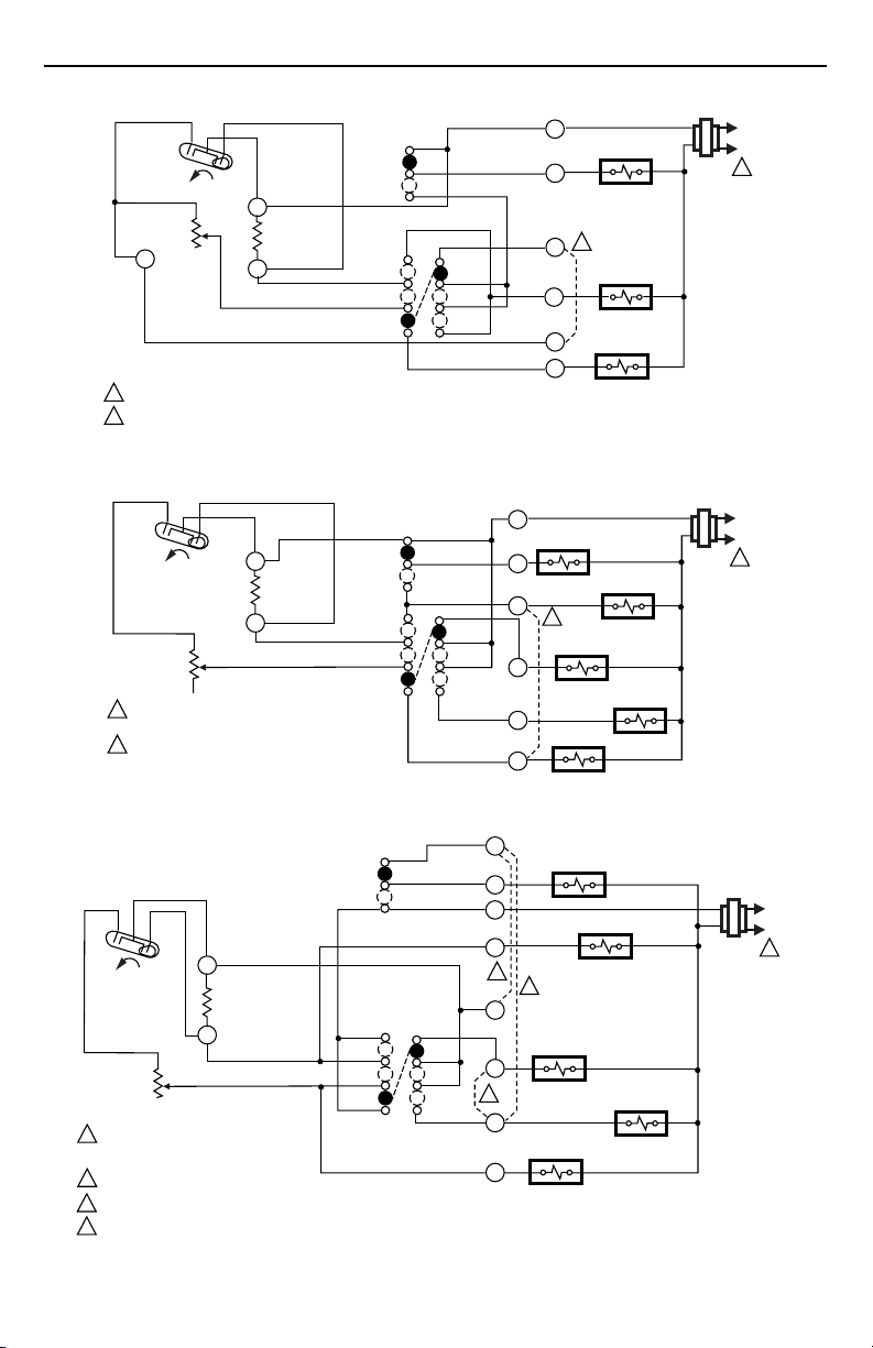
FAN SWITCH
H1
H1
ANTICIPATOR
1
POWER SUPPLY. PROVIDE DISCONNECT MEANS AND OVERLOAD PROTECTION AS REQUIRED.
2
IN ELECTRIC HEAT APPLICATION, JUMPER 1 AND 2 FOR AUTO FAN IN HEATING.
H1
TEMP. FALL
H1
ANTICIPATOR
1
POWER SUPPLY. PROVIDE DISCONNECT MEANS AND
OVERLOAD PROTECTION AS REQUIRED.
2
INSTALL JUMPER BETWEEN W AND Y TERMINALS
WHEN HEAT RELAY IS NOT USED.
C1
TEMP. FALL
C1
ANTICIPATOR
Fig. 4. Internal schematic and typical hookup for T834C dual fuel model
in a gas- or oil-fired, or central electric heat system.
C1
C1
ANTICIPATOR
ON
AUTO
SYSTEM
SWITCH
COOL
OFF
HEAT
FAN SWITCH
ON
AUTO
SYSTEM
SWITCH
COOL
OFF
HEAT
HEAT
OFF
COOL
HEAT
OFF
COOL
R
G
Y
B
O
W
R
G
1
Y
2
W
FAN RELAY
2
CHANGEOVER
RELAY (HEAT)
HEAT RELAY
FAN RELAY
2
COMPRESSOR
CONTACTOR
HEAT RELAY
COMPRESSOR
CONTACTOR
CHANGEOVER
RELAY (COOL)
M1037C
L1
(HOT)
L2
1
M2035A
L1
(HOT)
L2
1
Fig. 5. Internal schematic and typical hookup for T834C in heat pump system with supplementary heat.
HEAT
OFF
COOL
1
G
R
O
3
2
W
4
Y
B
FAN RELAY
2
HEAT RELAY
CHANGEOVER
RELAY (HEAT)
CHANGEOVER
RELAY (COOL)
COMPRESSOR
RELAY
FAN SWITCH
AUTO
ON
H1
C1
TEMPERATURE
FALL
H1
ANTICIPATOR
1
POWER SUPPLY. PROVIDE DISCONNECT
MEANS AND OVERLOAD PROTECTION
AS REQUIRED.
2
JUMPER 1-Y FOR AUTO FAN IN COOLING ONLY.
3
JUMPER 1-2 FOR AUTO FAN WITH WAND Y.
4
JUMPER W-Y FOR SINGLE-STAGE HEAT PUMP.
Fig. 6. Internal schematic and typical hookup for T834C gas or oil-fired systems and single-stage
C1
ANTICIPATOR
SYSTEM
SWITCH
COOL
OFF
HEAT
heat pump or central electric heat.
3
L1
(HOT)
L2
1
M11342A
69-0444—10
 Loading...