

Page 1
APPLICATION
The T827B thermostat is for 24 Vac spst control of
heating-only systems.
Heat anticipation is fixed. The current rating is stamped on
the thermostat. The T827B has an adjustable heat
anticipator rating of either 0.18A to 0.8 A or 0.32A to 1.2A
at 30 Vac (depending on model). See Fig. 1.
INSTALLATION
When Installing this Product...
1. Read these instructions carefully. Failure to follow
them could damage the product or cause a hazardous condition.
2. Check the ratings given in the Instructions and on
the product to make sure the product is suitable for
your application.
3. Installer must be a trained, experienced service
technician.
4. After installation is complete, check out product
operation as provided in these Instructions.
CAUTION
Disconnect power supply before beginning
installation to prevent electrical shock or equipment
damage.
Location
Locate the thermostat about 5 ft (1.5m) above the floor in
an area with good air circulation at room temperature.
Do not mount the thermostat where it can be affected by:
— drafts, or dead spots behind doors and in corners.
— hot or cold air from ducts.
— radiant heat from the sun or appliances.
— concealed pipes and chimneys.
— unheated (uncooled) areas such as an outside wall
behind the thermostat.
This is a precision instrument. Rough handling can
decrease its accuracy.
Handle it carefully.
T827B
Heating Thermostat
INSTALLATION INSTRUCTIONS
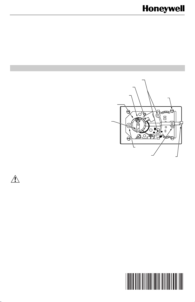
MOUNTING CLIPS
(2) (FOR COVER)
SNAP SWITCH
CONTACTS
BIMETAL ELEMENT
BEHIND HEAT
ANTICIPATOR SCALE
ADJUSTABLE HEAT
ANTICIPATOR
SCALE
ADJUSTABLE
HEAT
ANTICIPATOR
INDICATOR
LEVER
Fig. 1. Internal view of T827B with adjustable heat
.1
MOUNTING HOLES
(THERMOSTAT
TO WALL OR
OUTLET BOX)
anticipator.
Wiring and Mounting
All wiring must comply with local codes and ordinances.
쐃 In replacement applications, inspect the old wiring
for frayed or cracked insulation. Replace any wires
in poor condition. In new installations, run two wires
to the chosen location.
쐇 Grasp the thermostat cover on the sides with one
hand. Pull outward on the left edge of the cover until
it snaps free of the thermostat base. Remove and
discard the shipping tab that protects the switch
contacts during shipping.
쐋 Connect the thermostat wires to the appropriate
terminals on the back of the thermostat. See Fig. 2
for typical hookup. Push any excess wire back
through the hole and plug any opening to prevent
drafts that can affect thermostat performance.
쐏 Adjust the heat anticipator to match the current draw
of the primary control in the system. See Heat
Anticipator Setting section.
MOUNTING
POSTS (4)
(FOR COVER)
.8
.6
.4
.3
TEMPERATURE
SETTING LEVER
M8502A
Copyright © 1995 Honeywell Inc. • All Rights Reserved
X-XX UL
69-0974
Page 2

T827B HEATING THERMOSTAT
쐄 Fasten the thermostat to the wall or outlet box with
screws through the mounting holes on each side of
the device. See Fig. 1. Level the thermostat for best
appearance.
쐂 Replace the thermostat cover.
T827
TH
THTRTR
GAS VALVE
POWER SUPPLY. PROVICE DISCONNECT MEANS AND
1
OVERLOAD PROTECTION AS REQUIRED.
COMBINATION FAN
AND LIMIT CONTROL
TRANSFORMER
LIMIT FAN
FAN
MOTOR
(HOT)
1
L1
L2
M7779
Fig. 2. Typical hook up for the T827B.
SETTING AND CHECKOUT
Temperature Setting
Move the temperature setting lever to the desired setpoint
on the thermostat scaleplate. See Fig. 1. Temperature will
be controlled to that point.
Heat Anticipator Setting
IMPORTANT
1. Use this thermostat only with controls that
have current ratings equal to (or within) the
rating of the heat anticipator.
2. The T827B Thermostat is equipped with an
adjustable heat anticipator and will operate
properly ONLY IF THIS HEATER IS ADJUSTED TO MATCH THE CURRENT DRAW
OF THE PRIMARY VALVE OR RELAY.
3. Do not use the T827B Thermostat on
The T827B features an adjustable heat anticipator rated
from either 0.18A to 0.8A or 0.32A to 1.2A at 30 Vac
(depending on model). This heat anticipator must be
adjusted to match the current draw of the primary control
for optimum thermostat performance. The rating of the
primary control is stamped on the control nameplate. To
adjust, move the anticipator indicator lever to correspond
to the control rating. See Fig. 1.
®
Powerpile
Thermostat is designed for use on Powerpile
(millivoltage) Systems.
(millivolt) Systems. The TS810
If the setting and current rating are not available, wire the
thermostat into the system, but do not attach it to the wall.
If the thermostat is already mounted, remove it from the
wall, leaving it connected to the system wiring.
Connect an ammeter of the appropriate range (about 0.0A
to 2.0A) between the terminals on the back of the thermostat. Move the temperature setting lever to a low setting so
that the contacts are broken. In cold weather, it may be
necessary to hold the switch so the controls remain open.
Allow the system to operate through the ammeter for one
minute. Adjust the anticipator to match the meter reading.
NOTE: For best performance, the heat anticipator may
require further adjustment. To lengthen burner-on
time, move the indicator in the direction of the
longer
arrows, but not more than one-half scale
marking at a time. To shorten burner-on time,
move the indicator in the opposite direction.
CHECKOUT
CAUTION
Do not check operation by shorting across
terminals of system controls. This will damage the
heat anticipator.
IMPORTANT
To assure accurate temperature control, do not
touch or breathe on bimetal of thermometer.
Observe the system through at least one complete automatic
cycle. Make certain that the system operates as intended.
CALIBRATION
This thermostat is carefully calibrated at the factory and
should not need adjustment in the field. If the thermostat
seems out of adjustment, check as follows:
쐃 Move the temperature setting lever to the lowest
setting of the temperature scale. Wait at least five
minutes.
쐇 Remove the thermostat cover. Slowly move the
®
temperature lever until the snap switch just makes
contact.
쐋 Replace the cover and wait five minutes for the
cover and the thermostat to lose the heat gained
from your hands. If the thermometer pointer and the
setting lever indicator read approximately the same,
no recalibration is needed.
If the thermostat needs recalibration, order Open-end
Wrench, part no. 104994A. Follow the recalibration
instructions furnished with the wrench.
Automation and Control Solutions
Honeywell International Inc.
1985 Douglas Drive North
Golden Valley, MN 55422
69-0974
69-0974 J.S. 11-95
Honeywell Limited-Honeywell Limitée
35 Dynamic Drive
Scarborough, Ontario M1V 4Z9
2
www.honeywell.com/yourhome
 Loading...