

Page 1
T822C,E
Cooling Thermostats
Application
T822C,E Thermostats provide low voltage control of
cooling systems. Both models have fixed cooling anticipators and are available with a positive OFF switch and
temperature range stops. The T822E has ON-AUTO fan
switching and OFF-AUTO system switching.
Recycling Notice
M3375
This control contains mercury in a sealed tube. Do not
place control in the trash at the end of its useful life.
If this control is replacing a control that contains mercury in a sealed tube, do not place your old control in the
trash.
Contact your local waste management authority for
instructions regarding recycling and the proper disposal
of this control, or of an old control containing mercury in
a sealed tube.
If you have questions, call Honeywell at 1-800-468-
1502.
Installation
WHEN INSTALLING THIS PRODUCT...
1. Read these instructions carefully. Failure to follow them could damage the product or cause a hazardous condition.
2. Check the ratings given in the Instructions and
on the product to make sure the product is suitable for
your application.
3. Installer must be a trained, experienced service
technician.
4. After installation is complete, check out product
operation as provided in these Instructions.
CAUTION
Disconnect power supply before beginning installation to prevent electrical shock or equipment damage.
LOCATION
Locate the thermostat about 5 ft [1.5 m] above the
floor on an inside wall in an area with good air circulation at average temperature.
Do not mount the thermostat where it can be affected
by:
—drafts or dead spots behind doors or in corners.
—hot or cold air from ducts.
—radiant heat form the sun, fireplaces, or appliances.
—concealed pipes and chimneys.
—unheated (uncooled) areas behind the thermostat
such as an outside wall.
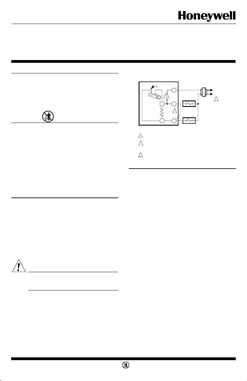
Fig. 1—T822C in typical cooling application
with fan relay.
T822C
TEMP. RISE
R
3
C1
C1
ANTICIPATOR
1
POWER SUPPLY. PROVIDE DISCONNECT MEANS AND OVERLOAD
PROTECTION AS REQUIRED.
2
CONNECT FAN TO O FOR CONTINUOUS FAN OPERATION.
CONNECT FAN TO Y FOR FAN OPERATION WITH COOLING
EQUIPMENT CYCLING.
3
POSITIVE OFF SWITCH PROVIDES COMPLETE CONTROL
CIRCUIT SHUTOFF. DOES NOT REPLACE POWER SUPPLY
DISCONNECT SWITCH.
O
2
Y
FAN RELAY
COMPRESSOR
RELAY
L1
(HOT)
L2
1
M1292A
MOUNTING AND WIRING
Disconnect power supply before beginning installa-
tion to prevent electrical shock or equipment damage.
All wiring must comply with local codes and ordinances. T822C,E Thermostats are designed to be vertically mounted on a wall or an outlet box.
1. In replacement applications, check the existing
thermostat wires for cracked or frayed insulation. Replace any wires in poor condition. If the wire is plastered
into the wall, make a hole next to the wires and loosen
the wires so that they can be pushed back into the wall
later.
2. In new installations, run wiring (if necessary) to
the thermostat location.
3. Connect the wires to the terminals on the back of
the thermostat. See Figs. 1, 2, or 3 for internal schematics and typical hookup diagrams.
4. Remove thermostat cover by pulling outward on
bottom edge of cover until it snaps free of the thermostat
base. Carefully remove and discard the foam plastic
shipping insert. This insert protects the switch and bimetal assembly during shipping.
5. Push excess wire back through the hole and plug
any opening with insulation to prevent drafts that may
affect thermostat performance.
6. Loosely fasten the thermostat to the wall or outlet
box with a screw through the top mounting hole. Do not
tighten.
7. Level the thermostat exactly using a spirit level or
plumb line. Tighten the mounting screws.
IMPORTANT: An incorrectly leveled thermostat will
cause the temperature control to deviate from
setpoint.
8. Replace the thermostat cover.
1 69-0548—2J. H. • Rev. 2-93 • • ©Honeywell Inc. 1993 • Form Number 69-0548—2
M3375
Page 2
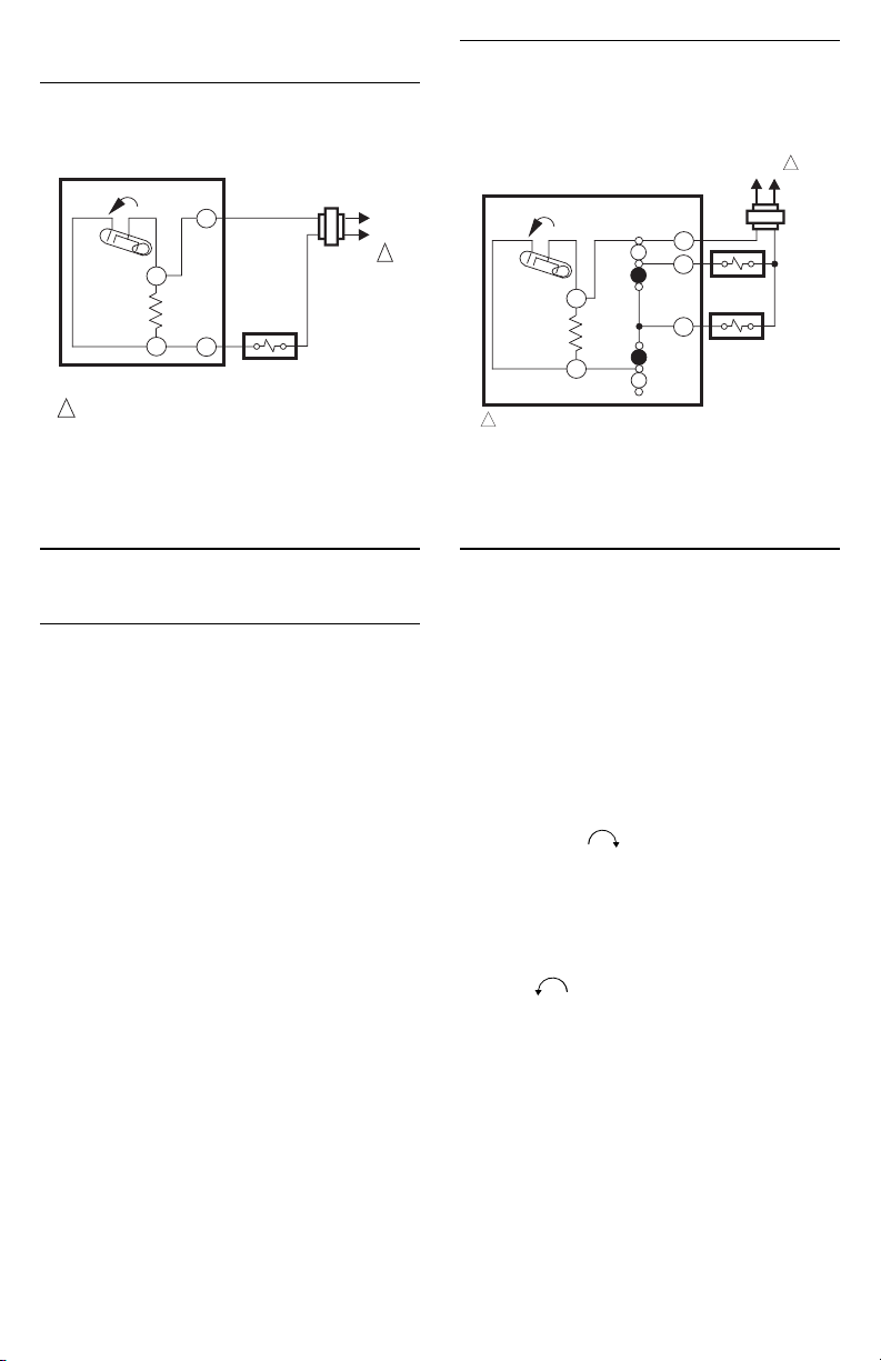
Fig. 2—T822C in typical cooling application.
T822C
TEMP. RISE
R
C1
C1
ANTICIPATOR
Y
COMPRESSOR
RELAY
1
POWER SUPPLY. PROVIDE DISCONNECT MEANS AND OVERLOAD
PROTECTION AS REQUIRED.
M2305
L1
(HOT)
L2
1
Fig. 3—T822E in typical cooling application.
L1
(HOT)
FAN RELAY
COMPRESSOR
CONTACTOR
L2
T822E
TEMP. RISE
C1
C1
ANTICIPATOR
1
POWER SUPPLY. PROVIDE DISCONNECT MEANS AND OVERLOAD
PROTECTION AS REQUIRED.
FAN
SWITCH
ON
AUTO
SYSTEM
SWITCH
AUTO
OFF
R
G
Y
1
M1293
Settings and Adjustment
TEMPERATURE SETTING
Move the temperature setting lever to the desired
control point on the temperature scale. On positive OFF
models, the control circuit is broken when the lever is
moved to the extreme high end of the temperature scale.
T822E FAN AND SYSTEM SWITCHING
The fan switch controls fan operation as follows:
AUTO— fan operates in response to the thermostat
call for cooling.
ON— fan operated continuously.
The system switch controls system operations as
follows:
OFF—cooling control system is disabled.
AUTO—cooling control system operates in response
to the thermostat call for cooling.
RECALIBRATION
These thermostats are calibrated at the factory and
should not need recalibration. If the thermostat seems
out of adjustment, first check for accurate leveling. To
check calibration, proceed as follows:
1. Move the temperature setting lever to the low end
of the temperature scale.
2. Remove the thermostat cover. Move the setting
lever until the switch just makes contact. The mercury in
the switch will drop to the contact end of the tube.
3. Replace cover and wait five minutes for the cover
and the thermostat to lose the heat it has gained from
your hands. If the thermostat pointer and the setting
lever indicator read approximately the same, no
recalibration is needed.
If recalibration appears necessary, proceed as fol-
lows:
1. Place the temperature setting lever at the same
setting as the thermometer. Remove cover.
2. Insert 104994A Calibration Wrench (order separately) onto the hex nut under the coil. See Fig. 4.
Holding the setting lever so it does not move, turn the
wrench clockwise until the switch just breaks contact. Remove wrench and replace cover.
3. Move the setting lever to a low setting. Wait at
least five minutes for temperature to stabilize.
4. Slowly move the setting lever until it reads the
same as the thermometer.
5. Remove cover. Holding the setting lever so it does
not move, reinsert wrench and carefully turn counterclockwise until the mercury just rolls to the left
end of the tube but no farther.
6. Recheck calibration. Set thermostat system switch
for desired operation and replace cover.
2
Page 3

Checkout
CAUTION
Do not check thermostat operation by shorting
across system control terminals. This damages
the thermostat heat anticipator.
T822C,E COOLING THERMOSTATS
CAUTION
Do not operate cooling circuit if outdoor temperature is 50° F [10° C] below room temperature.
Refer to air conditioner manufacturer recommendations.
NOTE: To prevent compressor short cycling, a mini-
mum off-timer may be included to provide a five
minute time delay before reactivating the compressor
or after compressor receives power.
1. Set T822E SYSTEM switch to AUTO and FAN
switch to AUTO. Fan and system operation are now
controlled by the thermostat.
2. Move temperature setting lever about 10° F [6° C]
below room temperature. Cooling and fan start immediately.
3. Move temperature setting lever about 10° F [6° C]
above room temperature. Cooling and fan stop immediately.
4. Set T822E SYSTEM switch to AUTO and FAN
switch to ON. Fan runs continuously.
5. Set T822E SYSTEM switch to OFF. Cooling
control system is disabled.
6. Set temperature lever and T822E SYSTEM and
FAN switches to the desired settings.
Fig. 4—Recalibration procedure.
COIL SHOWN WITHOUT
HEAT ANTICIPATOR
CALIBRATION
WRENCH
M2044
3 69-0548—2
Page 4

Home and Building Control Home and Building Control
Honeywell Internationl, Inc. Honeywell Limited—Honeywell Limitée
1985 Douglas Drive North 35 Dynamic Drive
Golden Valley, MN 55422 Scarborough, Ontario
M1V 4Z9
4
Printed in U.S.A. on recycled
paper containing at least 10%
post-consumer paper fibers.
 Loading...