

Page 1
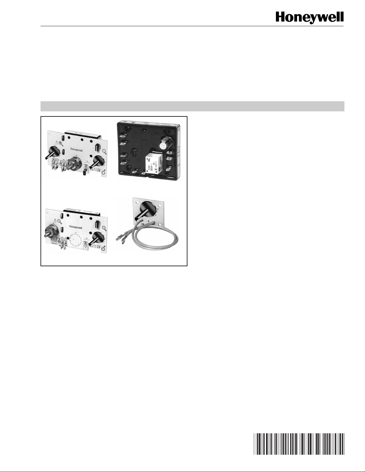
T8205B,C, TS8205B,C Electronic Pool,
Spa Control Systems; T8205A,H, TS8205A Control
Modules; Q8205A-C Setpoint Panels and Sensor Assembly
PRODUCT DATA
FEATURES
• T8205 requires 24 Vac power supply; TS8205 is used in
a 750 mV self-generating system.
• T8205B,C and TS8205B,C include an electronic control
module and setpoint panel packaged together to
simplify installation. The sensor must be ordered
separately.
T8205C T8205A
TS8205B Q8205A
APPLICATION
T8205B,C and TS8205B,C Electronic Pool and Spa Control
Systems are used in pool, spa, and hot tub applications to
control water temperature. T8205B,C and TS8205B,C Control
System components include a T8205A,H or TS8205A Control
Module and Q8205A-C Setpoint Panel. Sensor Assembly is
purchased separately. The T8205A and TS8205A Control
Modules and Q8205A-C Setpoint Panels can be purchased
separately. The T8205H Control Module is for use with heat
pump systems only. Q8205A-C Setpoint Panels can be used
for remote applications.
• T8205A and TS8205A Control Modules are used with a
sensor and Q8205A-C Setpoint Panel.
• T8205H Control Module is for use with heat pump
systems only and has 1/4 in. quick connect terminals.
• Module controls within 1.5°F (0.8°C) at setpoint of
106°F (41°C).
• Models available for single control or dual control of
combination pool and spa.
• Isolated relay contacts in electronic control modules
operate gas control or ignition module.
• Male quick-connect wiring terminals provided on
electronic control modules.
• Sensor with 3/16 in. female quick connects on 42 in.,
48 in., 50 in., or 96 in. leadwires can be directly
immersed or mounted in well.
• Setpoint panel can be remotely mounted.
• Plastic potentiometers and selector switches provide
increased protection from humidity and chlorine.
• Combination of 1/4 in. and 3/16 in. quick connect
terminals provide ANSI miswiring compliance, except
T8205H Control Module.
Copyright © 1998 Honeywell Inc. • All Rights Reserved
Contents
Application........................................................................... 1
Features .............................................................................. 1
Specifications ...................................................................... 2
Ordering Information ........................................................... 2
Installation ........................................................................... 5
Settings ............................................................................... 7
Checkout ............................................................................. 7
Operation ............................................................................ 8
Troubleshooting ................................................................... 8
68-0177-1
Page 2
T8205B,C, TS8205B,C ELECTRONIC POOL, SPA CONTROL SYSTEMS;
T8205A,H, TS8205A CONTROL MODULES; Q8205A-C SETPOINT PANELS AND SENSOR ASSEMBLY
SPECIFICATIONS
IMPORTANT
The specifications given in this publication do not
include normal manufacturing tolerances. Therefore,
this unit may not exactly match the listed
specifications. Also, this product is tested and
calibrated under closely controlled conditions, and
some minor differences in performance can be
expected if those conditions are changed.
Models:
T8205B,C and TS8205B,C Electronic Pool, Spa and Hot
Tub Control Systems provide single or dual water
temperature control in pool, spa, or hot tub applications.
Order Sensor Assembly separately. See Table 5.
Table 1. T8205B,C 24 Vac Control Systems
Control System Control Rating Potentiometers Switch Positions Heat-On LED LED Terminal N.C. Contacts
T8205B 24 Vac 1 On-Off yes yes yes
T8205B 24 Vac 1 On-Off no no no
T8205C 24 Vac 2 Pool-Off-Spa no no no
T8205C 24 Vac 2 Pool-Off-Spa no yes no
T8205C 24 Vac 2 Pool-Off-Spa yes yes no
T8205C 24 Vac 2 Pool-Off-Spa yes yes yes
T8205B,C and TS8205B,C include electronic control
module and setpoint panel with one or two
potentiometers with selector switch, and on select
models, an LED Heat-On display. See Tables 1
through 3.
T8205A,H, TS8205A Control Modules available separately.
See Table 3.
T8205H is for use with Heat Pump Systems only.
Q8205A,B,C Setpoint Panels available separately for
remote applications. See Table 4.
Separate Components:
To order components separately, see Tables 3 through 5.
Table 2. TS8205B,C Millivolt Control Systems. Table 3. T8205A/TS8205A Control Modules.
Control
System
TS8205B 750 mV 1 On-Off
TS8205C 750 mV 2 Pool-Off-Spa
Control
Rating Potentiometers
Switch
Positions
Control
Module
T8205A 24 Vac N.C.—optional optional
T8205H 24 Vac N.O./N.C. not available
TS8205A 750 mV not available not available
Control
Rating Contacts
LED
Terminal
ORDERING INFORMATION
When purchasing replacement and modernization products from your wholesaler or your distributor, refer to the price sheets for
complete ordering number, or specify:
1. Order numbers for Control System and Sensor Assembly; or Control Module, Setpoint Panel and Sensor Assembly.
2. Leadwire length for Q8205A-C.
3. For T8205B,C: Heat-On LED, LED Terminal and N.C. Contacts, as desired. See Table 2 for availability.
4. For T8205A, TS8205A, Q8205A-C optional features as desired. See Tables 3 and 4 for availability.
5. Accessories, if required.
If you have additional questions, need further information, or would like to comment on our products or services, please write or
phone:
1. Your local Honeywell Home and Building Control Sales Office (check white pages of phone directory).
2. Home and Building Control Customer Logistics
Honeywell Inc., 1985 Douglas Drive North
Minneapolis, Minnesota 55422-4386
In Canada—Honeywell Limited/Honeywell Limitée, 35 Dynamic Drive, Scarborough, Ontario M1V 4Z9.
International Sales and Service Offices in all principal cities of the world. Manufacturing in Australia, Canada, Finland, France,
Germany, Japan, Mexico, Netherlands, Spain, Taiwan, United Kingdom, U.S.A.
68-0177—1
2
Page 3

T8205B,C, TS8205B,C ELECTRONIC POOL, SPA CONTROL SYSTEMS;
T8205A,H, TS8205A CONTROL MODULES; Q8205A-C SETPOINT PANELS AND SENSOR ASSEMBLY
Table 4. Q8205A-C Setpoint Panels.
Panel Potentiometers
Q8205A 1 none none
Q8205B 1 On-Off none
Q8205C 2 Pool-Off-Spa optional
Electrical Ratings:
T8205 Power Supply: 18-30 Vac, 60 Hz.
T8205 Power Consumption: 3 VA at 24 Vac.
TS8205 Power Supply: 750 mV, dc.
Relay Contacts: Inductive: 2A full load, 10A locked rotor.
Resistive: 2A.
Temperature Setting Range:
61° to 106°F (16° to 41°C).
Setpoint Adjustment:
10K ohm, one-turn potentiometer.
Setpoint Accuracy:
±1.5°F (0.8°C) at 106°F (41°C).
Ambient Temperature Range at Module:
T8205: -40° to +175°F (-40° to + 80°C).
TS8205: 0 to 175°F (0° to 80°C).
Differential (Not field adjustable):
1°F (0.7°C) maximum at 106°F (41°C), subtractive.
Switch
Positions LED
Mounting:
T8205B,C and TS8205B,C Control Systems are mounted
on the appliance through mounting holes on the device.
Sensors are mounted directly into the header or in a
well.
IMPORTANT
T8205A,H, TS8205A Control Modules and Q8205AC Setpoint Panels must be mounted to allow
adequate electrical spacing according to approval
agency requirements.
T8205A,H and TS8205A Control Modules mount on any
flat surface using no. 6 screws (obtained locally)
through mounting holes.
Q8205A-C Setpoint Panels mount through holes on board
using no. 6 screws (obtained locally).
Sensing Bulb:
Can be mounted in immersion well or directly immersed,
using fittings to prevent leakage. Well or fitting supplied by
heater manufacturer.
Approvals:
International Approval Services (American Gas
Association and Canadian Gas Association) (IAS)
Certificate: C2030021.
Meets ANSI Standard Z21.23-1993.
Accessory:
Part no. 107408 Heat Conductive Compound in 4 oz. can.
Use when mounting sensor in a well.
Sensor:
NTC thermistor sensor is imbedded in a copper bulb. Includes
leadwires with 3/16 in. female quick connects.
See Table 5.
Table 5. Sensors.
Sensor Termination Lead Length Diameter Capsule Length Mounting Material
198799E 3/16 in. quick connect 42 in. (1067 mm) 3/8 in. (10 mm) 2 in. (51 mm) Compression Copper
198799F 1/4 in. quick connect 48 in. (1219 mm) 3/8 in. (10 mm) 3 in. (76 mm) Compression Copper
198799H 3/16 in. quick connect 42 in. (1067 mm) 3/8 in. (10 mm) 2-5/8 in. (67 mm) Spud Copper
198799K 3/16 in. quick connect 42 in. (1067 mm) 3/8 in. (10 mm) 2 in. (51 mm) Compression Monel
198799R 3/16 in. quick connect 48 in. (1219 mm) 3/8 in. (10 mm) 3 in. (76 mm) Compression Copper
198799S 3/16 in. quick connect 96 in. (2438 mm) 3/8 in. (10 mm) 2-5/8 in. (67 mm) Spud Copper
198799W 3/16 in. quick connect 50 in. (1270 mm) 3/8 in. (10 mm) 2 in. (51 mm) Compression Copper
Optional Features:
T8205B,C: LED indicator available for Heat-On indication.
Specify when ordering.
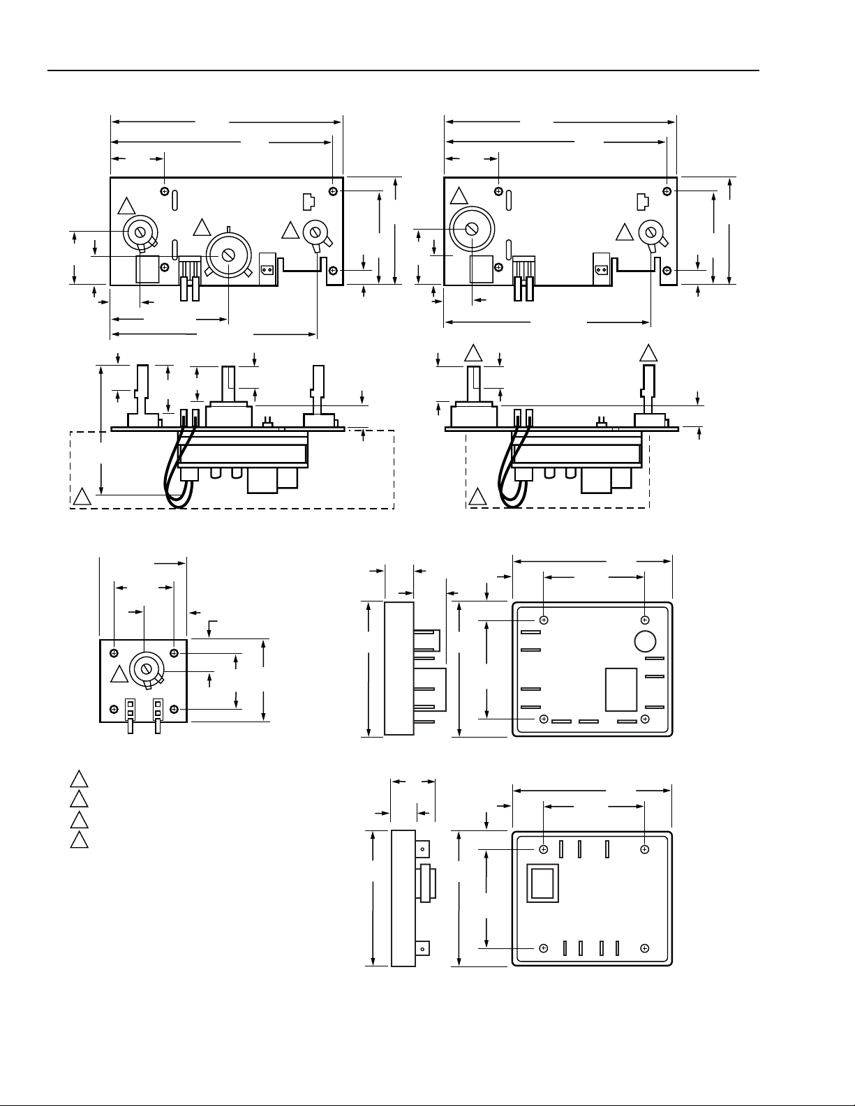
Dimensions:
See Fig. 1 for T8205B,C; TS8205B,C; Q8205A; T8205A,H;
TS8205A dimensions. See Table 5 for sensor dimensions.
3
68-0177—1
Page 4
T8205B,C, TS8205B,C ELECTRONIC POOL, SPA CONTROL SYSTEMS;
T8205A,H, TS8205A CONTROL MODULES; Q8205A-C SETPOINT PANELS AND SENSOR ASSEMBLY
1-1/4
(32)
Q8205C DUAL POTENTIOMETER PANEL
5-5/16
(135)
1-1/4
(32)
2
2
3/4
(19)
11/16
(17)
2-11/16 (68)
4-11/16 (119)
5/8
(16)
2-3/4
(70)
1
1-1/8
(29)
13/16 (21)
1/2 (13)
5-1/8
(130)
Q8205B SINGLE POTENTIOMETER PANEL
5-5/16
(135)
1-1/4
(32)
3/4
(19)
13/16
(21)
2
11/16
(17)
4-11/16 (119)
4 3
1/2 (13)
1
3
(76)
2
5/16 (8)
5/8 (16)
2-1/8
(54)
1-1/4
(32)
5-1/8
(130)
3
(76)
2
5/16 (8)
5/8 (16)
2-1/8
(54)
Q8205A SETPOINT PANEL T8205A,H POTTED CONTROL MODULE
1-13/16
(46)
2
COM
1-5/16
(33)
15/16
(24)
POT 1
9/16
(14)
1-1/8
(29)
1-5/8
(41)
(76)
17/32
(13)
11/16
(2)
3
2-5/8
(67)
11/32 (9)
1-31/32
(50)
17/32
(13)
TS8205A POTTED CONTROL MODULE
1
THIS SECTION ON T8205B,C MODELS ONLY.
2
3/8 IN. (10 MM) RECOMMENDED FOR SHAFT CLEARANCE HOLE.
3
POTENTIOMETER SHAFT DIAMETER .24 IN. (6 MM).
4
SWITCH SHAFT DIAMETER .25 IN. (6 MM).
(76)
1
(25)
(50)
17/32
(13)
1/2
(13)
11/32 (9)
3
2-5/8
(67)
1-31/32
1-31/32
(50)
1-31/32
(50)
3 (76)
3 (76)
68-0177—1
M11013B
Fig. 1. T8205B,C; TS8205B,C; Q8205A; T8205A,H; TS8205A dimensions in in. (mm).
4
Page 5

T8205B,C, TS8205B,C ELECTRONIC POOL, SPA CONTROL SYSTEMS;
T8205A,H, TS8205A CONTROL MODULES; Q8205A-C SETPOINT PANELS AND SENSOR ASSEMBLY
INSTALLATION
When Installing this Product…
1. Read these instructions carefully. Failure to follow them
could damage the product or cause a hazardous
condition.
2. Check the ratings given in the instructions and on the
product to make sure the product is suitable for your
application.
3. Installer must be a trained, experienced service
technician.
4. After installation is complete, check out product
operation as provided in these instructions.
WARNING
Explosion Hazard.
Can cause property damage, severe injury
or death.
This product is for use only in a system with a
pressure relief valve.
WARNING
Burn Hazard.
Can cause severe personal injury.
Always
use a separate high limit temperature control
to prevent possible overheating of pool or spa water.
CAUTION
Electrical Shock Hazard.
Can cause electrical shock or equipment damage.
Disconnect power supply before beginning wiring.
IMPORTANT
Sensor leadwires can be damaged by bending or
pulling when exposed to below-freezing
temperatures. Install only when temperature is above
32
°
F (0°C).
The T8205B,C and TS8205B,C Control Systems can be
mounted on the appliance through mounting holes on the
device. Mount in a location that is below high temperature
limits but within range of the sensor leadwires. Mount the
Setpoint Panels through holes on the board.
T8205A,H and TS8205A Control Modules mount on any flat
surface using no. 6 screws (obtained locally) through the
mounting holes.
Setpoint Panel
For remote mounting, the Q8205 Setpoint Panel can be
mounted in any convenient location for reading and changing
the temperature setting. Mount through holes on the board
using no. 6 screws (obtained locally). T8205A,H and TS8205A
Control Modules and Q8205A-C Setpoint Panels must be
mounted to allow adequate electrical spacing according to
approval agency requirements.
Wiring
WARNING
Burn Hazard
Can cause severe personal injury.
Always
use with a separate high limit temperature
control to prevent possible overheating of the pool or
spa water.
IMPORTANT
For most reliable operation, run the sensor leadwires
separately from any other current-carrying wires.
The T8205C is a combination of the T8205A and the Q8205C.
Fig. 2 shows the T8205A,H Control Module latched into the
back side of the Q8205C Setpoint Panel. See Fig. 4 and 5 for
system wiring diagrams.
COMMON
LOAD
24V HOT
SENSOR
FOR LED
TERMINALS
Q8205C
Location and Mounting
Sensor
Locate the sensor in the return water header of the heater at a
point where average pool, spa, or hot tub water temperature
can be measured. The sensor can be installed in an immersion
well, or directly immersed.
If an immersion well is used, fit the bulb snugly touching the
bottom of the well for best temperature response. Use heatconductive compound (available from Honeywell in a four
ounce can as part no. 107408). Make sure the bulb is held
firmly in the well.
If the bulb is directly immersed, use a 3/8 in. x 1/2 in.
compression to MIP coupling or O-ring and clamp to prevent
leaks and keep the sensor leadwires dry.
Wells and fittings must be supplied by the heater manufacturer.
Control Systems
IMPORTANT
TS8205A Control Module and Q8205A-C Setpoint
Panels must be mounted to allow adequate electrical
spacing according to approval agency requirements.
HOT
ONLY
T8205A
WIRING TERMINALS
FOR ONE OR TWO
POTENTIOMETERS
Fig. 2. T8205C: T8205A Control Module
and back side of Q8205C Setpoint Panel.
The TS8205B is a combination of the TS8205A and Q8205B.
Fig. 3. shows the TS8205 Control Module latched into the
back side of the Q8205B Setpoint Panel. See Fig. 6 for
system wiring diagram.
5
M11120A
68-0177—1
Page 6

T8205B,C, TS8205B,C ELECTRONIC POOL, SPA CONTROL SYSTEMS;
T8205A,H, TS8205A CONTROL MODULES; Q8205A-C SETPOINT PANELS AND SENSOR ASSEMBLY
TS8205A
–(TH/PP)
SENSOR
TERMINALS
+(PP)
VALVE (TH)
WIRING TERMINALS
FOR ONE OR TWO
POTENTIOMETERS
Q8205B
M11121A
Fig. 3. TS8205B: TS8205A Control Module
and back side of Q8205B Setpoint Panel.
All wiring must comply with local codes and ordinances.
Disconnect power supply before beginning wiring. Wire
according to instructions provided by the heater manufacturer,
or connect as shown in Fig. 4 through 8.
T8205B
Q8205B
SWITCH
2
T8205A
POT
3
POT
SEN SEN
LOAD
COM
24V
HOT
ONLY
POT
T8205C
Q8205C
L1
(HOT)
L2
POT
SWITCH
2
T8205A
3
SENSOR
1
24 VAC
MAIN
VALVE
MV
S8600
MV/
PV
COM
PILOT
VALVE
FUSE
PV
GAS
VALVE
GND
BURNER
24V
GND
POT
POT
SEN SEN
LIMIT(S)
IGNITION
HOT TH-W
1
POWER SUPPLY. PROVIDE
DISCONNECT MEANS AND
OVERLOAD PROTECTION
AS REQUIRED.
2
Q8205C HAS TWO
POTENTIOMETERS, Q8205B
HAS ONE POTENTIOMETER.
3
FACTORY WIRED ON T8205B,C.
VENT
DAMPER
PLUG
LOAD
COM
24V
HOT
ONLY
POT
SPARK
M11015B
Fig. 5. T8205B,C (TS8205B,C has similar wiring
configuration) wired to ignition module to control water
temperature in both pool spa, or hot tub (T8205C shown).
SENSOR
L1
(HOT)
L2
1
2
3
1
24 VAC
POWER SUPPLY. PROVIDE DISCONNECT MEANS AND OVERLOAD
PROTECTION AS REQUIRED.
Q8205B HAS ONE POTENTIOMETER, Q8205C HAS TWO
POTENTIOMETERS.
FACTORY WIRED ON T8205B,C.
FUSE
TH
LIMIT(S)
TR
VR8200
GAS VALVE
M11014B
Fig. 4. T8205B,C (TS8205B,C has similar wiring
configuration) wired to 24V gas control to control water
temperature in pool, spa, or hot tub (T8205B shown).
68-0177—1
6
Page 7

T8205B,C, TS8205B,C ELECTRONIC POOL, SPA CONTROL SYSTEMS;
T8205A,H, TS8205A CONTROL MODULES; Q8205A-C SETPOINT PANELS AND SENSOR ASSEMBLY
TS8205B
Q8205B
SENSOR
SWITCH
3
SEN
SEN
POT
POT
POLARITY IS CRITICAL. FOLLOW POLARITY MARKINGS WHEN WIRING. FAILURE TO
1
DO SO RESULTS IN MALFUNCTION.
2
LIMIT ACTION WITH HIGH LIMIT WIRED BETWEEN GAS CONTROL AND GENERATOR LOCKS OUT
HEATER UNTIL PILOT IS MANUALLY RELIT. ALTERNATE HIGH LIMIT LOCATION ALLOWS AUTOMATIC
HEATER RESTART AFTER LIMIT SWITCH REMAKES.
3
FACTORY WIRED ON TS8205B,C.
TS8205A
-(TH/PP)
+(PP)
VALVE
(TH)
POT
ALTERNATE
HIGH LIMIT CONTROL
LOCATION (AUTO RECYCLE)
TH
2
PP
TH
PP
HIGH LIMIT
CONTROL
(MANUAL
RELIGHT)
Fig. 6. TS8205B,C wiring connections for high limit control (TS8205B shown).
2
_
+
1
Q313
POWERPILE
MILLIVOLT
GENERATOR
M11016B
®
POT
T8205H
POT 1
24 VAC
HOT
POT 2
N.O.
24 VAC
C
COM
SEN SEN N.C.
CONTACTOR
M15513
(HOT)
LIMIT(S)
24 VAC
L1
L2
FUSE
SENSOR
Fig. 7. T8205H wiring connections for heat pump heating
applications.
POT
T8205H
POT 1
24 VAC
HOT
POT 2
N.O.
24 VAC
C
COM
SEN SEN N.C.
CONTACTOR
M15514
(HOT)
LIMIT(S)
24 VAC
L1
L2
FUSE
SENSOR
Fig. 8. T8205H wiring connections for heat pump cooling
applications.
SETTINGS
Select Control Temperature
The control temperature is set by turning the setpoint
potentiometer. The limit of clockwise rotation with the shaft
toward you represents the maximum 106°F (41°C) setting.
Turning the potentiometer counterclockwise through its full
rotation moves the setting to the minimum limit. On models
with two potentiometers, one potentiometer is used to set the
pool temperature, and the other is used to set the spa
temperature. See Fig. 9 for a setting guide.
CHECKOUT
Check out the system by observing it through at least one
complete cycle, making sure it operates as desired. Check
the sensor by comparing its resistance to the temperature as
measured by an accurate thermometer. The resistance of the
sensor increases as its temperature drops. The
troubleshooting chart, Fig. 10, shows the relationship
between sensor resistance and temperature.
7
68-0177—1
Page 8

T8205B,C, TS8205B,C ELECTRONIC POOL, SPA CONTROL SYSTEMS;
T8205A,H, TS8205A CONTROL MODULES; Q8205A-C SETPOINT PANELS AND SENSOR ASSEMBLY
0° REFERENCE ANGLE WITH FLAT OF SHAFT
PARALLEL TO TOP OF BOARD AS SHOWN
95°F
90°F
19°
TOP
173°
COM POT 1 POT 2
65°F
DIVIDE POTENTIOMETER ROTATION INTO SEGMENTS TO
DETERMINE SETPOINT. USE LINE THROUGH CENTER OF
SHAFT PERPENDICULAR TO FLAT AS REFERENCE.
TEMPERATURE SETTING °F
TEMPERATURE SETTING °C
TOLERANCE °F
100°F
1°
19°
38°
65
90
18
32
±3
±3
106°F
95
35
+5
-2
Fig. 9. Relationship between potentiometer
position and temperature setting.
100
38
+3
OPERATION
The T8205A,H and TS8205A Control Modules use a potentiometer to set the operating temperature and an external sensor
assembly to sense the actual water temperature. The T8205A,H
and TS8205A are used with the Q8205A-C. The T8205B,C and
the TS8205B,C include the Q8205B,C. The setpoint potentiometer on the Q8205 is used to set the operating temperature.
On models with two potentiometers, one is used to set the pool
temperature, and the other is used to set the spa temperature.
Relay contacts in the module close to turn on the gas control or
ignition module when the temperature at the sensor drops 1°F
(0.5°C) below the setpoint. When the temperature rises to the
setpoint, the relay contacts open, turning off the gas control or
ignition module.
Control range is 61° to 106°F (16° to 41°C) with a fixed
subtractive differential of 1°F (0.7°C) maximum at 106°F (41°C).
TROUBLESHOOTING
106
41
±1.5
-4
M11122B
The following procedures describe methods for
troubleshooting the T8205 and TS8205 Control Systems
when the pool/spa/hot tub are too hot or too cold.
• When the pool/spa/hot tub water is too cold, use Fig. 10 to
troubleshoot the system.
• When the pool/spa/hot tub water is too hot, use Fig. 11 to
troubleshoot the system.
68-0177—1
8
Page 9

T8205B,C, TS8205B,C ELECTRONIC POOL, SPA CONTROL SYSTEMS;
T8205A,H, TS8205A CONTROL MODULES; Q8205A-C SETPOINT PANELS AND SENSOR ASSEMBLY
CHECK VOLTAGE: T8205/Q8205 24V TERMINALS;
TS8205/Q8205 + AND - TERMINALS.
NO
YES
VOLTAGE: T8205/Q8205 BETWEEN 21.5 TO 28.5V;
TS8205/Q8205 BETWEEN +0.2V AND 0.75V.
SET CONTROL TO MAXIMUM TEMPERATURE. AFTER
TWO TO THREE HEATING CYCLES, CHECK WATER
TEMPERATURE.
YES
VOLTAGE OUTSIDE RANGE: T8205/Q8205 21.5 TO 28.5V;
CHECK TRANSFORMER AND 120V SUPPLY; CORRECT
AS NECESSARY. TS8205/Q8205 +0.2V TO 0.75V,
CHECK GENERATOR; CORRECT AS NECESSARY.
NO
TEMPERATURE BELOW 105°F (40°C).
DISCONNECT SENSOR LEADS FROM CONTROL.
MEASURE SENSOR RESISTANCE WITH OHMMETER.
YES
RESISTANCE 1 TO 15K ohms.
CHECK WATER TEMPERATURE; ESTIMATE EXPECTED
SENSOR RESISTANCE FROM SENSOR RESISTANCE TABLE.
TEMPERATURE
60°F (16°C)
70°F (21°C)
80°F (27°C)
90°F (32°C)
106°F (41°C)
EXPECTED
SENSOR RESISTANCE
15K ohms
12K ohms
9K ohms
7K ohms
5K ohms
YES
MEASURED AND ESTIMATED RESISTANCE
MATCH WITHIN 20 PERCENT.
DISCONNECT POTENTIOMETER LEADS FROM CONTROL.
MEASURE RESISTANCE WITH OHMMETER.
IF RESISTANCE IS:
0 TO 100 ohms AT MINIMUM SETTING;
9 TO 11K ohms AT MAXIMUM SETTING,
REPLACE CONTROL MODULE.
ABOVE 11K ohms, REPLACE SETPOINT PANEL.
ABOVE 15K ohms, FIX LOOSE OR BROKEN WIRES;
REPLACE IF NECESSARY.
RECONNECT ALL LEADS AND CHECK OUT SYSTEM.
1
1
TEMPERATURE 105° (40°C) TO 106°F (41°C).
CONTROL OK; CHECK BALANCE OF SYSTEM.
NO
RESISTANCE 0 ohms (SHORT CIRCUIT).
CHECK SYSTEM FOR SHORTED WIRES. REPLACE
SENSOR, IF NECESSARY.
NO
MEASURED AND ESTIMATED
RESISTANCES DO NOT MATCH.
REPLACE SENSOR. RECONNECT ALL LEADS AND CHECK
OUT SYSTEM.
1
FOR T8205B,C/TS8205B,C MODELS REPLACE THE CONTROL SYSTEM.
FOR T8205A,H/TS8205A MODELS, REPLACE THE T8205A,H/TS8205A OR
Q8205A–C AS APPROPRIATE.
M11018A
Fig. 10. Troubleshooting procedure when water is too cold.
9
68-0177—1
Page 10

T8205B,C, TS8205B,C ELECTRONIC POOL, SPA CONTROL SYSTEMS;
T8205A,H, TS8205A CONTROL MODULES; Q8205A-C SETPOINT PANELS AND SENSOR ASSEMBLY
CHECK VOLTAGE: T8205/Q8205 24V TERMINALS;
TS8205/Q8205 + AND - TERMINALS.
NO
YES
VOLTAGE: T8205/Q8205 BETWEEN 21.5 TO 28.5V;
TS8205/Q8205 BETWEEN +0.2V TO 0.75V
SET CONTROL TO MAXIMUM TEMPERATURE. AFTER
TWO TO THREE HEATING CYCLES, CHECK WATER
TEMPERATURE.
YES
VOLTAGE OUTSIDE RANGE: T8205/Q8205 21.5 TO 28.5V;
CHECK TRANSFORMER AND 120V SUPPLY; CORRECT
AS NECESSARY. TS8205/Q8205 +0.2V TO 0.75V,
CHECK GENERATOR; CORRECT AS NECESSARY.
NO
TEMPERATURE ABOVE 106°F.
DISCONNECT SENSOR LEADS FROM CONTROL.
MEASURE SENSOR RESISTANCE WITH OHMMETER.
YES
RESISTANCE 1 TO 15K ohms.
CHECK WATER TEMPERATURE; ESTIMATE EXPECTED
SENSOR RESISTANCE FROM SENSOR RESISTANCE
TABLE. SEE FIG. 8.
YES
MEASURED AND ESTIMATED RESISTANCE
MATCH WITHIN 20 PERCENT.
DISCONNECT POTENTIOMETER LEADS FROM CONTROL.
MEASURE RESISTANCE WITH OHMMETER.
IF RESISTANCE IS:
0 TO 100 ohms AT MINIMUM SETTING;
9 TO 11K ohms AT MAXIMUM SETTING,
REPLACE CONTROL MODULE.
ABOVE 11K ohms, REPLACE SETPOINT PANEL.
ABOVE 15K ohms, FIX LOOSE OR BROKEN WIRES;
REPLACE IF NECESSARY.
0 ohms (SHORT CIRCUIT), REPLACE SETPOINT PANEL.
RECONNECT ALL LEADS AND CHECK OUT SYSTEM.
1
TEMPERATURE 105°F (40°C) TO 106°F (41°C).
CONTROL OK. CHECK BALANCE OF SYSTEM.
NO
RESISTANCE ABOVE 15K ohms (OPEN CIRCUIT).
FIX LOOSE OR BROKEN WIRES. REPLACE SENSOR, IF NECESSARY.
NO
MEASURED AND ESTIMATED RESISTANCE
DO NOT MATCH.
REPLACE SENSOR. RECONNECT ALL LEADS AND CHECK
OUT SYSTEM.
1
1
1
FOR T8205B,C/TS8205B,C MODELS REPLACE THE CONTROL SYSTEM.
FOR T8205A,H/TS8205A MODELS, REPLACE THE T8205A,H/TS8205A OR
Q8205A–C AS APPROPRIATE.
M11019A
68-0177—1
Fig. 11. Troubleshooting procedure when water is too hot.
10
Page 11

T8205B,C, TS8205B,C ELECTRONIC POOL, SPA CONTROL SYSTEMS;
T8205A,H, TS8205A CONTROL MODULES; Q8205A-C SETPOINT PANELS AND SENSOR ASSEMBLY
11
68-0177—1
Page 12

T8205B,C, TS8205B,C ELECTRONIC POOL, SPA CONTROL SYSTEMS;
T8205A,H, TS8205A CONTROL MODULES; Q8205A-C SETPOINT PANELS AND SENSOR ASSEMBLY
Automation Control and Solutions
Honeywell International Inc.
1985 Douglas Drive
Golden Valley, MN 55422
Honeywell Limited-Honeywell Limitée
35 Dynamic Drive
Scarborough, Ontario M1V 4Z9
Honeywell Asia Pacific Inc.
Room 3213-3225
Sun Hung Kai Centre
No. 30 Harbour Road
Wanchai
Hong Kong
Honeywell Latin American Revion
480 Sawgrass Corporate Parkway
Suite 200
Sunrise FL 33325
68-0177—1
68-0177—1 J.S. Rev. 2-98 customer.honeywell.com
Honeywell Europe S.A.
3 Avenue du Bourget
1140 Brussels
Belgium
12
 Loading...