

Page 1
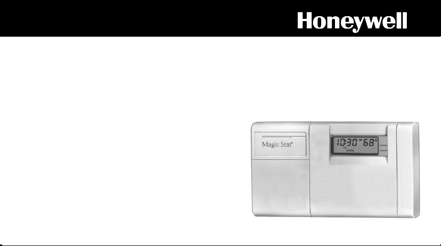
Honeywell
PROGRAMMABLE
THERMOSTAT
BY HONEYWELL
MagicStat/
T8132
PROGRAMMING AND INSTALLATION
INSTRUCTIONS
Rev. 9-92 • Form Number 69-0740B—1
Programmable Heat and/or Cool
Weekday/Weekend
Thermostat and Mounting Plate
Model T8132
Page 2

Welcome to the world of comfort and energy savings with your new Honeywell MagicStat
TM
programmable thermostat.
Your new thermostat will automatically control the temperature in your home, keeping you
comfortable while saving energy when programmed according to the instructions in this manual.
Any questions concerning the application of this thermostat should be directed to Honeywell
Customer Assistance at 1-800-468-1502, Monday-Friday 7:00 a.m.-5:30 p.m., Central time.
Page 3

Table Of Contents
STEP 1 Prepare For Installation ............................................................................................... 2
STEP 2 Remove Old Thermostat .............................................................................................. 4
STEP 3 Install The Batteries ..................................................................................................... 6
STEP 4 Program The Thermostat ............................................................................................. 8
STEP 5 Adjust Fan Operation Switch, as Required .............................................................. 16
STEP 6 Adjust System On-Length as Required .................................................................... 16
STEP 7 Mount Thermostat Mounting Plate............................................................................ 18
STEP 8 Wire Thermostat Terminals ....................................................................................... 20
STEP 9 Mount The Thermostat ............................................................................................... 24
STEP 10 Check Thermostat Operation After Programming and Installing ........................ 25
STEP 11 Set The Fan and System Switches ........................................................................ 27
Troubleshooting Guide............................................................................................................ 28
Limited One-Year Warranty ..................................................................................................... 33
1
Page 4
STEP 1
Prepare For Installation
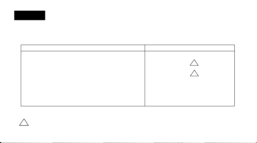
■■ Check Table 1 to make sure this thermostat is compatible with your system. If not, return to
retailer. For more information, call Honeywell Customer Assistance, toll-free 1-800-468-1502.
TABLE 1—COMPATIBILITY CHART.
System Type Compatible With CT3200
Gas—Standing Pilot Yes
Gas—Electronic Ignition Yes
Gas-Fired Boilers Yes
Gas—Millivolt No
Oil-Fired Boilers Yes
Oil-Fired Furnace Yes
Electric Furnace Yes
Electric Air Conditioning Yes
Baseboard Electric (120/240 Line Volt) No
Heat Pumps/Multistage Equipment No
1
1
Not compatible with any 120/240 volt circuit.
Will not work efficiently on steam or gravity systems.
1
Compatible with 2-wire Honeywell zone valves. Isolating relay required for 3-wire thermo-
stats for zone valves. Not compatible with 2-wire White-Rodgers #1361 valves.
2
Page 5
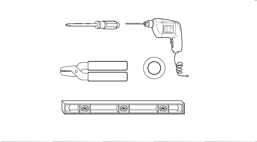
■■ Acquire tools and items as needed (below). Also purchase two AA alkaline batteries; we
recommend Energizer batteries
CROSS-RECESSED
SCREWDRIVER
WIRE CUTTER/STRIPPER OR SHARP
KNIFE, IF NEEDED TO STRIP WIRES
SPIRIT LEVEL, IF NEEDED TO LEVEL
THERMOSTAT FOR APPEARANCE
HAND OR POWER
DRILL WITH 3/16 INCH
DRILL BIT, IF NEEDED TO
DRILL HOLES IN WALL
MASKING TAPE, IF NEEDED
TO LABEL WIRES AS THEY
ARE DISCONNECTED FROM
OLD THERMOSTAT
3
M 878
Page 6

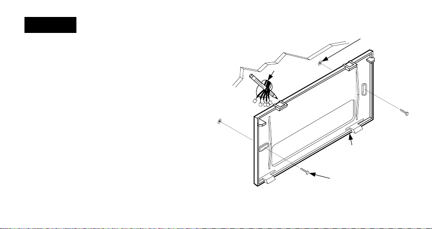
STEP 2
WIRES THROUGH
WALL OPENING
M5136
Remove Old Thermostat
■■ Test to make certain that your heating
and cooling systems are working properly. If
either does not work, contact your local heating/
air conditioning dealer. To avoid compressor
damage, do not operate the cooling system
when outdoor temperature is below 10° C [50°
F].
■■ TURN OFF POWER to system at the
furnace, or at the fuse/circuit breaker panel.
■■ Carefully unpack your new thermostat and
mounting plate; save package of screws,
instructions and receipt.
■■ Remove cover from old thermostat. If it does
not snap off when pulled firmly from the bottom,
check for a screw used to lock on the cover.
■■ Loosen screws holding thermostat to
subbase, wallplate or wall, and lift away.
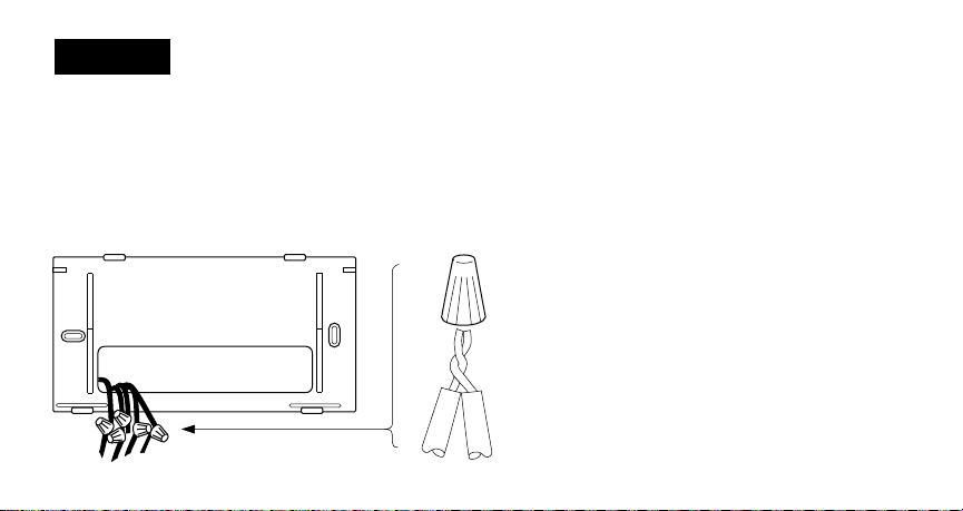
■■ Disconnect wires from old thermostat or
subbase. As you disconnect each wire, use
masking tape to label it with the old terminal
designation. If there are only two wires, they do
not need to be labeled. Keep the wires from
falling back into the wall by wrapping them
around a pencil, as shown.
4
Page 7

WIRES THROUGH
WALL OPENING
M5136
One or two extra wires?
If you are replacing a Honeywell
Chronotherm thermostat, you may find one
or two wires that go to the C or C1 clock
terminals on the Chronotherm thermostat wiring
wallplate. Do not allow them to touch,
or you may damage your transformer. Disconnect the wires and wrap them separately, using
electrical tape.
Do not wrap them together
.
Place the wires where they will not interfere with
the operation of the new thermostat. Record the
colors and terminal designation labels of the
remaining wires.
Six or more wires?
If there are six or more wires (excluding
clock wires attached to terminals), you
most likely have a variation of a heat pump
or multistage system. The thermostat is
not
compatible with such systems so return
the product to the place of purchase. If you
would like information about which programmable thermostats will work with your system,
call Honeywell Customer Assistance at
1-800-468-1502.
Three thermostat wires?
If you have three wires for heating only and
can operate the fan using the fan ON switch,
this thermostat will work with your system.
However, some hot water (zoned) heating
systems have three thermostat wires. The
thermostat will not work without installing an
isolating relay on these systems. Call Honeywell Customer Assistance at 1-800-468-1502
for details.
5
Page 8

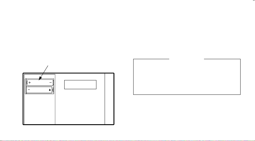
STEP 3
Install The Batteries
IMPORTANT
Batteries must be installed for programming
and operation of the thermostat and heating/
cooling system.
■■ Purchase two AA alkaline batteries; non-
alkaline batteries will not last as long. We recommend Energizer batteries.
■■ Make sure the thermostat is set in OFF position.
■■ Use a coin to remove battery door.
■■ Install the fresh batteries as shown,
making sure positive and negative terminals are
oriented correctly.
■■ Replace battery door.
6
REMOVING
BATTERY
DOOR
M1719B
As the batteries are running low, a “bAt Lo” indicator will flash for 1-2 months before batteries
run out completely. Replace the batteries as
soon as possible after the indicator starts
flashing. If you do not replace the batteries
sometime during the flashing “bAt Lo” indicator,
the indicator will eventually stop flashing. “bAt Lo”
Page 9
will stay on without flashing to indicate the
thermostat and heating/cooling system have
stopped working when the batteries are almost
completely dead.
After the batteries are completely dead, the
“bAt Lo” indicator will disappear, leaving a
completely blank display.
Press down on left ends of batteries to remove.
If you insert the new batteries within 20-30
INSTALL TWO AA ALKALINE
BATTERIES AS SHOWN
seconds of removing the old ones, you will not
have to reprogram the thermostat. However, if
the display is blank, the batteries are dead or
incorrectly installed. In this case, you will have to
reprogram. See pages 12-13 to reprogram.
IMPORTANT
Although the thermostat has a low battery
indicator, replace the batteries once a year to
prevent the thermostat and heating/cooling
system from shutting down due to lack of
battery power.
When leaving home for longer than a month,
as a precaution, change batteries before you
leave to prevent system from shutting down due
to lack of battery power.
M1713
7
Page 10

STEP 4
Program The Thermostat
After the batteries are installed, the thermostat
can be easily programmed in your hand, before
it is installed on the wall.
If you would prefer to program the thermostat
after it is installed on the wall, skip to page 16,
and return later to this programming section.
The following personal programming chart
(pages 10-11) may be helpful for planning your
program schedule of time and temperature
settings for various times of the day.
Four time periods are available during
weekdays — “WAKE”, “LEAVE”, “RETURN”,
and “SLEEP”. These periods can be seen
individually on the display as you press the
SET SCHEDULE key.
“WAKE” is the time period you want the
house at a comfortable temperature after you
get up, while you get ready for work or
school. (This will be a higher temperature
during heating season, or a lower temperature during cooling season.)
“LEAVE” is the time period you can set for an
energy-saving temperature while you are
away at work or school. (This will be a lower
temperature during heating season, or a
higher temperature during cooling season.)
“RETURN” is the time period you want the
house at a comfortable temperature for
activities before bedtime. (Again, higher heat
or lower cool.)
“SLEEP” is the time period you can set for an
energy-saving temperature while you are
8
Page 11

sleeping. (Again, lower heat or higher cool.
Although for more comfortable sleeping,
some people choose not to raise the cool
temperature during the night.)
You will set one schedule for weekdays and
another for weekends, since your requirements
will probably be different for each. Also, during
weekends only the “WAKE” and “SLEEP” time
periods are available.
Fill in the times and temperatures you desire for
weekdays and weekends. If you decide not to
program the thermostat, it will automatically
control heating at 20° C [68° F], and cooling at
26° C [78° F], 24 hours a day. Also, you do not
need to enter a time and temperature program
for all periods if your schedule does not require
it. For example, a house that is occupied during
weekdays would not require programs for
“LEAVE” and “RETURN”.
When pressing the keys, use the ball of your
finger or a soft pencil eraser. Use of sharp
fingernails or pencil points may damage the
keypad.
If at any time during programming you make an
error, just press the RUN PROGRAM key, and
continue again at the step where you left off.
PROGRAMMING
9
Page 12
Personal Programming Chart
HEATING PROGRAM
Weekdays Start Time Heating Temperature
WAKE
LEAVE
RETURN
SLEEP
Weekends
WAKE
SLEEP
1
If you decide not to enter weekend programs, the WAKE and SLEEP from the
weekday program will copy to the weekend schedule.
2
The temperatures cannot be set any higher than 31° C [88° F] or any lower than
7° C [45° F].
1
10
2
Page 13
COOLING PROGRAM
Weekdays Start Time Cooling Temperature
WAKE
LEAVE
RETURN
SLEEP
2
Weekends
1
WAKE
SLEEP
1
If you decide not to enter weekend programs, the WAKE and SLEEP from the weekday
program will copy to the weekend schedule.
2
The temperatures cannot be set any higher than 31° C [88° F] or any lower than 7° C [45° F].
NOTE: If you decide not to program the thermostat, it will automatically control heating at
20° C [68° F], and cooling at 26° C [78° F], 24 hours a day.
PROGRAMMING
11
Page 14
This guide can be used for programming your new thermostat.
NOTE: Batteries are required for operation and programming. When inserting batteries, set
system switch to OFF. Remove battery door (on thermostat left side) using a coin at the bottom.
Follow instructions on pages 6-7.
Set Current Time/Day
To set time, press and release once, until current time shows; to set day,
Set
Clock/Day
Time
Ahead
Back
Time
press and release again, until current day shows; then press .
Set
Clock/Day
Heating Program
With system switch at HEAT, press and release once. “WAKE”, Mon-Fri and “SET”
Ahead
Back
Set
Schedule
Run
Program
appear on display.
12
Page 15
Time
Ahead
Temp
Warmer
Use to program “WAKE” time and to program “WAKE” temperature for
Back
Cooler
Mon-Fri. Repeat sequence for “LEAVE”, “RETURN”, “SLEEP”.
Press until “WAKE”, “SA SU” and “SET” appear on display. Use to program
Set
Schedule
Temp
Warmer
Time
Ahead
Back
“WAKE” time and to program “WAKE” temperature for Sat-Sun. Repeat sequence
for “SLEEP”.
Cooler
Cooling Program
With system switch at COOL, follow same instructions as for Heating Program.
After programming, adjust fan and system switches as desired. Press and release to start
the program.
PROGRAMMING
13
Run
Program
Page 16
A quick guide for operating or making changes follows:
Warmer
Cooler
NOTE: System switch must be set to Heat or Cool to perform the following.
Temp
Temporarily Change temperature for current period only— ;
will cancel itself at next scheduled change, or to cancel sooner press .
Temp
Hold a temperature indefinitely— , ; to cancel press .
Hold
Temp
Warmer
Cooler
14
Run
Program
Run
Program
Page 17
Check Current Temperature Setting— . (If using TEMPORARILY CHANGE
Ahead
Back
Warmer
Cooler
Run
Program
or HOLD, pressing this will cancel your change.)
Check Programs— repeatedly to see each time and temperature; then .
Set
Schedule
Time
Cancel a program— until program to cancel shows; then together.
Set
Schedule
Permanently Change a program—Repeat steps under Heating Program or Cooling Program
(page 12-13) as applicable.
Return to normal program or start program — .
PROGRAMMING
Run
Program
15
Questions?
Call Honeywell
Customer Assistance
1-800-468-1502.
Run
Program
Page 18
STEP 5
Adjust Fan Operation Switch, As Required
■■ The thermostat fan operation switch, labeled
FUEL SWITCH (see figure on page 17) is factoryset in the “F” position. This is the correct setting for
most systems. If your system is an electric heat
STEP 6
Adjust System On-Length As Required
■■ The thermostat on-length is factory-set for a
warm air, gas or oil heating system. If you are
installing it on another type of system, the on-length
must be adjusted accordingly by setting screws A
and B on the back of the thermostat, using the
heating system table in the figure
In the rare event that you want a longer on-length, you may readjust the screws as follows:
If on-length screws A,B are adjusted For longer on-length, readjust screws A,B
to match this system: to match this system:
electric furnace warm air furnace
warm air furnace hot water boiler
system, set the switch to “E”. The “E” setting will
allow the fan to turn on immediately with the
heating or cooling in a system where the “G”
terminal is connected.
(page 17) as a guide. The on-length should be
optimized according to the type of system to
minimize room temperature swings. Setting the
screw “out one turn” means turning the screw
approximately 360°, or about one complete turn.
16
Page 19
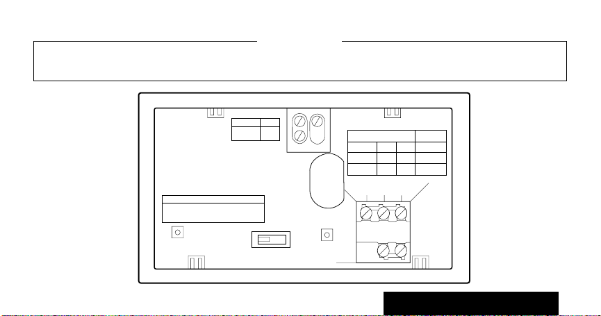
NOTE: This thermostat does not have a setting for steam/gravity air. Cycles would not be long
R
Rc
W Y G
B D
A C
THERMOSTAT BACK
DISPLAY °F
DISPLAY °C
C–IN
C–OUT
1 TURN
FOR HIGH EFFICIENCY FURNACE (90%+ AFUE)
ADJUST: SCREW A–OUT 1 TURN
SCREW B–IN
FUEL SWITCH – F POSITION
F
E
FUEL SWITCH
WARM AIR
FURNACE
HOT WATER
BOILER
ELECTRIC
FURNACE
A–IN
A–OUT
1 TURN
A–IN
ADJUST SCREWS THROUGH HOLES
TO SELECT OPERATION DESIRED
B–IN
B–IN
B–OUT
1 TURN
FUEL SWITCH
POSITION
F
F
E
HEATING SYSTEM
enough for accurate temperature control.
IMPORTANT
When using a high efficiency furnace such as a 90% or greater AFUE (Average Fuel Utilization
Efficiency) unit, adjust screw A out one turn and screw B in.
17
INSTALLATION
Page 20
STEP 7
(2)
Mount Thermostat Mounting Plate
■■ Position mounting plate on wall. Use spirit
level to make sure mounting plate is level. Use
a pencil to mark the two mounting holes.
WIRES THROUGH
WALL OPENING
WALL
WALL
ANCHORS (2)
MOUNTING
PLATE
M1718
18
MOUNTING
SCREWS
Page 21
■■ Remove mounting plate from wall, and drill
(
)
3/16" holes in wall (if drywall) as marked. For
firmer material such as plaster or wood, drill
7/32" holes. Gently tap anchors (provided) into
drilled holes until flush with the wall.
■■ Reposition mounting plate over holes, pulling
wires through wiring opening. Loosely insert two
mounting screws into holes.
■■ Level for appearance only; thermostat will
function properly even when not level. Tighten
mounting screws.
SPIRIT LEVEL
M1714
19
INSTALLATION
Page 22
STEP 8
Wire Thermostat Terminals
NOTE: All wiring must comply with local codes
and ordinances. If unsure about household
wiring procedures, call your local heating/air
conditioning contractor.
Refer to masking tape labels you placed on wires
when you removed your old thermostat.
■■ Match the letter of your old thermostat wire
with the terminal of the corresponding letter on the
back of your new thermostat. Refer to figures on
pages 22-23 and Table 2 for typical wire colors for
METHOD TO INCREASE WIRE LENGTH
easy matching. Hold the thermostat as shown to
minimize need for wire extenders. If wires are still
WIRE NUT SIZE
FOR TWO
18-GAUGE WIRES
WIRE
M1715A
FROM
WALL
6-in. [152 mm] OF
18-GAUGE
THERMOSTAT
WIRE. MATCH
INSULATION
COLORS OR
MARK WIRE ENDS.
20
too short, use wire connectors
(purchase locally) to extend wires.
See figure (left)
for guidelines on using wire
extenders.
■■ In 5-wire installations only,
be sure to remove the factoryinstalled jumper connecting
terminals R and Rc .
Page 23

TABLE 2—TYPICAL WIRE COLORS AND FUNCTIONS.
THERMOSTAT CONNECT TO
TERMINAL WIRE COLOR
a
FUNCTION
G Green Fan
Y Yellow Cooling
W White Heating
Rc Blue Air Cond. Power
R Red Furnace Power
a
Wire colors are typical; verify at heating/cooling
equipment connection.
■■ Loosen the terminal screws and slip each
wire beneath its matching terminal. See figure
(lower right) for wire insertion technique.
Tighten terminals securely.
■■ Plug the hole in the wall with insulation to
help prevent drafts from adversely affecting
thermostat operation.
PROPER WIRING TECHNIQUE
5/16 in.
[8 mm]
STRIP
21
INSERT
STRAIGHT
UNDER
SCREW HEAD
END OF WIRE
VISIBLE HERE
JUMPER (FACTORYINSTALLED) REMOVE
IF 5-WIRE SYSTEM
c
R
R
WY G
INSTALLATION
M3002
M1712A
Page 24

2-WIRE HEAT-ONLY (JUMPER INTACT)
A C
B D
W Y G
R
L1
(HOT)
L2
JUMPER
HEATING
RELAY OR
VALVE COIL
1
POWER SUPPLY. PROVIDE DISCONNECT MEANS AND
OVERLOAD PROTECTION AS REQUIRED.
Rc
M1709A
4-WIRE HEAT/COOL (JUMPER INTACT)
A C
B D
W Y G
Rc
R
HEATING
RELAY OR
VALVE COIL
1
1
COOLING
CONTACTOR
COIL
FAN
RELAY
POWER SUPPLY. PROVIDE DISCONNECT MEANS AND
OVERLOAD PROTECTION AS REQUIRED.
JUMPER
L1
(HOT)
L2
M1710A
22
Page 25

5-WIRE HEAT/COOL (JUMPER REMOVED)
A C
B D
W Y G
3-WIRE COOL-ONLY (JUMPER INTACT)
A C
B D
W Y G
JUMPER
R
HEATING
RELAY OR
VALVE COIL
COOLING
1 1
L1
(HOT)
CONTACTOR
COIL
FAN
RELAY
L2
1
POWER SUPPLY. PROVIDE DISCONNECT MEANS AND
OVERLOAD PROTECTION AS REQUIRED.
Rc
L1
(HOT)
L2
M1711A
23
R
COOLING
CONTACTOR
COIL
FAN
RELAY
1
POWER SUPPLY. PROVIDE DISCONNECT MEANS AND
OVERLOAD PROTECTION AS REQUIRED.
Rc
INSTALLATION
L1
(HOT)
L2
M 848
Page 26

Mount The Thermostat
STEP 9
B.
A.
ENGAGE TABS AT TOP OF
THERMOSTAT AND MOUNTING PLATE.
PRESS LOWER EDGE
OF CASE TO LATCH.
NOTE: To remove thermostat from wall, first pull out at
bottom of thermostat, removing top last.
M 879
24
C.
SWING COVER OPEN TO
CHECK OPERATION.
Page 27

Check Thermostat Operation After
Programming And Installing
STEP 10
HEATING
Do NOT check heating system
operation by jumpering thermostat
terminals at the primary control, such
as the gas valve, zone valve, oil
burner control. This will damage the
thermostat.
Auto On
Warmer
Cooler
25
Move the system switch to HEAT and
HeatCool Off
the fan switch to AUTO.
Press key until the setting is about
6° C [10° F] above room temperature.
Heating should start and the fan
should run after a short delay (immediately if fan operation switch is set in E
position).
Press key until setting is about
6° C [10° F] below room temperature.
The heating equipment should shut
off.
INSTALLATION
Page 28

COOLING
To avoid possible compressor
damage, do not operate the cooling
system when outside temperature
is below 10° C [50° F]. See compressor manu-facturer’s instructions
for further information.
NOTE: When cooling setting is
changed, thermostat may delay
up to five minutes before turning
on the air conditioner. This delay
protects the compressor.
Auto On
Cooler
Warmer
Auto On
26
HeatCool Off
Move the system switch to COOL
and the fan switch to AUTO.
Press key until setting is about
6° C [10° F] below room temperature. The cooling equipment and fan
should start.
Press key until the setting is about
6° C [10° F] above room temperature. The cooling equipment and fan
should stop.
HeatCool Off
Move the system switch to OFF,
with the fan switch still at AUTO.
The system and fan should be off.
Page 29

STEP 11
Set The Fan And System Switches
First set the fan switch.
COOL: The thermostat controls your
Then set the system switch.
FAN AUTO: Normal setting for most
homes. A single-speed fan will turn on
automatically with the air conditioner or
furnace. A two-speed fan will usually
run on high with the air conditioner and
on low with the furnace.
FAN ON: The fan runs continuously.
Use for improved air circulation during
special occasions or for more efficient
electronic air cleaning.
air conditioning system.
OFF: Both the heating and air condi-
tioning systems are off.
HEAT: The thermostat controls your
heating system.
Auto On
Auto On
HeatCool Off
HeatCool Off
HeatCool Off
27
INSTALLATION
Page 30

Troubleshooting Guide
I
F… THEN…
Display will not come on. ■ Set the system switch to OFF; remove batteries; insert
Temperature display will not go
lower than 7
31
° C [88° F] during programming. The setting range is 7° C to 31°C [45° F to 88°F].
Temperature change occurs at the ■ Check the program times for the period in
wrong times. question. Be sure that AM and PM indications
Heating will not come on. ■ Check that switch on thermostat is set to HEAT.
° C [45° F] or higher than ■ You have reached the temperature setting limit.
backwards for at least 5 seconds to reset thermostat;
replace batteries correctly. Display should come on.
■ Make sure batteries are fresh and installed correctly.
are correct. Make sure the current day and time are
correct. Reprogram if necessary.
■ Check the system fuse or circuit breaker and replace or
reset if necessary.
28
Page 31

■ If display is blank or says "bAt Lo," install fresh
batteries.
■ If temperature setting is higher than current temperature, and SYSTEM ON indicator is lit, contact Honeywell Customer Assistance at 1-800-468-1502.
Cooling will not come on. ■ Check that switch on thermostat is set to COOL.
■ Check the system fuse or circuit breaker and replace or
reset if necessary.
■ If display is blank or says "bAt Lo," install fresh
batteries.
■ The thermostat has a built-in time delay on cooling.
Allow 5 to 10 minutes after changing the setting before
the air conditioner starts.
■ If temperature setting is lower than current temperature, and SYSTEM ON indicator is lit, move system
switch from COOL to OFF for 10 minutes. After 10
minutes, return switch to COOL position. If air
29
Page 32

Cooling will not come on. (Cont.) conditioner comes on, compressor may have reached
its high limit temperature protection and shut down. If air
conditioner does not come on after the 10 minutes and
the SYSTEM ON indicator is lit, contact Honeywell
Consumer Services at 1-800-468-1502
■ If 2- or 4-wire installation, verify that R-Rc jumper is
.
installed.
The house is too warm or too cool. ■ Press RUN PROGRAM key to check the current
SYSTEM ON indicator is lit, but no ■ Allow time for the furnace to heat up and the fan to
heat is coming from the registers. come on before checking for heat at the register.
Furnace or air conditioner cycles ■ Check system setting on back of thermostat.
too frequently.
temperature setting.
■ If desired, change the temperature setting. See
page 14.
Check to make sure system on-length is set
correctly according to page 16.)
30
Page 33

The system cycle length ■ Readjust according to instructions on pages 16-17.
is too short or too long.
The thermostat's current ■ Check that the wiring hole in the wall behind the
setting does not match the wallplate has been plugged with insulation to
display temperature. prevent drafts which might adversely affect
thermostat operation.
■ Be aware that it is normal for the current setting
and display temperature to differ on occasion.
31
Page 34

Toll-free Customer Assistance
For all questions concerning this thermostat, please read and follow the instructions. If additional
assistance is needed, call Honeywell Customer Assistance toll-free at 1-800-468-1502, MondayFriday, 7:00 a.m. - 5:30 p.m. Central time.
Before you call, please have the following information available—thermostat model number and
date code, kind of heating/cooling system (i.e., hot water, warm air, oil, gas, etc.), number of wires
connected to the thermostat.
NOTICE
This equipment is a Class B digital apparatus, which complies with Canadian Radio Interference Regula-
tions, CRC c.1374.
32
Page 35

Limited One-Year Warranty
Honeywell warrants this product, excluding battery, to be free from defects in the workmanship or materials, under normal use and service, for
a period of one (1) year from the date of purchase by the consumer. If, at any time during the warranty period, the product is defective or malfunctions,
Honeywell shall repair or replace it (at Honeywell’s option) within a reasonable period of time.
If the product is defective,
(i) return it, with a bill of sale or other dated proof of purchase, to the retailer from which you purchased it, or
(ii) package it carefully, along with proof of purchase (including date of purchase) and a short description of the
malfunction, and mail it, postage prepaid, to the following address:
Honeywell Inc. in Canada: Honeywell Limited/Honeywell Limitée
Return Goods Department Product Services ON15-FFE
1050 Berkshire Lane 740 Ellesmere Road
Plymouth, MN 55441-4437 Scarborough, Ontario M1P 2V9
This warranty does not cover removal or reinstallation costs. This warranty shall not apply if it is shown by Honeywell that the defect or malfunction
was caused by damage which occurred while the product was in the possession of a consumer.
Honeywell’s sole responsibility shall be to repair or replace the product within the terms stated above. HONEYWELL SHALL NOT BE LIABLE FOR
ANY LOSS OR DAMAGE OF ANY KIND, INCLUDING ANY INCIDENTAL OR CONSEQUENTIAL DAMAGES RESULTING, DIRECTLY OR
INDIRECTLY, FROM ANY BREACH OF ANY WARRANTY, EXPRESS OR IMPLIED, OR ANY OTHER FAILURE OF THIS PRODUCT. Some
states do not allow the exclusion or limitation of incidental or consequential damages, so this limitation may not apply to you.
THIS WARRANTY IS THE ONLY EXPRESS WARRANTY HONEYWELL MAKES ON THIS PRODUCT. THE DURATION OF ANY IMPLIED
WARRANTIES, INCLUDING THE WARRANTIES OF MERCHANTABILITY AND FITNESS FOR A PARTICULAR PURPOSE, IS HEREBY
LIMITED TO THE ONE YEAR DURATION OF THIS WARRANTY. Some states do not allow limitations on how long an implied warranty lasts,
so the above limitation may not apply to you.
This warranty gives you specific legal rights, and you may have other rights which vary from state to state.
If you have any questions concerning this warranty, please write our Customer Assistance Center, Honeywell Inc., P.O. Box 524, MN27-2164,
Minneapolis, MN 55440-0524 or call 1-800-468-1502, Monday-Friday, 7:00 a.m. to 5:30 p.m., Central time. In Canada, write Retail Products ON1502H, Honeywell Limited/Honeywell Limitée, 740 Ellesmere Road, Scarborough, Ontario M1P 2V9.
33
Page 36

TYPICAL ENERGY SAVINGS FOR REPRESENTATIVE CITIES IN THE U.S. AND CANADA
Savings for Once-A-Day
10°F (5°C) decrease
30%
28%
26%
24%
22%
20%
18%
16%
14%
12%
10%
8%
6%
Approximate percentage of energy cost savings
4%
2%
Minneapolis
St. Paul
Montreal
Ottawa
Toronto
Edmonton
Regina
Winnipeg
Calgary
Moncton
North Bay
Quebec
St. John's
Thermostat patents pending.
Halifax Vancouver Denver
Buffalo
Cleveland
Milwaukee
Des Moines
Omaha
Salt Lake
City
Savings for Twice-A-Day
10°F (5°C) decrease*
Boston
Chicago
Detroit
Pittsburgh
Indianapolis
*Based on 10°F (5°C) decrease—(5°F (3°C) decrease
gives approximately 55 percent of these savings).
Cincinnati
Kansas City
St. Louis
Columbus
New York
Philadelphia
Seattle
Savings for 5°F (3°)
summer increase
Louisville
San
Portland
Francisco
Wash., D C
Dallas
Atlanta
Printed in Mexico • J.H. • ©Honeywell Inc. 1992
Los Angeles
San Diego
M2416A
Page 37

THERMOSTAT
PROGRAMMABLE
DE HONEYWELL
md
MagicStat
/
T8132
MANUEL DE PROGRAMMATION
ET D’INSTALLATION
9-92 • Publication no 69-0740B—1
Thermostat programmable et plaque de montage
pour systèmes de chauffage et (ou) de
refroidissement avec programmation pour la
semaine et la fin de semaine
Modèle T8132
Page 38

Votre nouveau thermostat électronique MagicStatmd de Honeywell vous ouvre la porte aux
économies d’énergie.
Votre nouveau thermostat réglera automatiquement la température de votre résidence à un
niveau de confort élevé tout en vous faisant réaliser des économies d’énergie. Il suffit de
programmer le thermostat conformément aux directives de ce manuel.
Pour de plus amples renseignements sur ce thermostat, s’adresser aux Services à la clientèle
de Honeywell en utilisant la ligne directe sans frais 1-800-468-1502 du lundi au vendredi entre
7 h et 17 h 30.
Page 39

TABLE DES MATIÈRES
ÉTAPE 1 Avant l’installation ...................................................................................................2
ÉTAPE 2 Retrait de l’ancien thermostat ................................................................................ 4
ÉTAPE 3 Installation des piles ................................................................................................ 6
ÉTAPE 4 Programmation du thermostat ............................................................................... 8
ÉTAPE 5 Réglage du commutateur du ventilateur, au besoin .......................................... 16
ÉTAPE 6 Réglage des cycles de fonctionnement au besoin .............................................16
ÉTAPE 7 Installation de la plaque de montage ...................................................................18
ÉTAPE 8 Raccordement des bornes du thermostat ...........................................................20
ÉTAPE 9 Installation du thermostat .....................................................................................24
ÉTAPE 10 Vérification de la programmation et de l’installation ......................................... 25
ÉTAPE 11 Réglage des commutateurs du ventilateur et du système ............................... 27
Guide de dépannage ................................................................................................................. 28
Garantie restreinte pour un an ................................................................................................ 32
1
Page 40

ÉTAPE 1
Avant l’installation
■■ Consulter le tableau 1 afin de s’assurer que le thermostat est compatible avec le système choisi. S’il ne
convient pas, le retourner au détaillant. Pour de plus amples renseignements, communiquer, sans frais, avec
les Services à la clientèle au numéro 1-800-468-1502.
TABLEAU 1 - TABLEAU DE COMPATIBILITÉ
Type de système compatible avec le CT3200
Gaz - veilleuse permanente oui
Gaz - allumage électronique oui
Chaudières à gaz oui
Gaz - tension millivolt non
Chaudières à mazout oui
Appareils de chauffage au mazout oui
Appareils de chauffage électrique oui
Conditionneur d’air électrique oui
Plinthes chauffantes électriques (120/240 V tension secteur) non
Pompes à chaleur/systèmes multi-étages non
Non compatible avec tout circuit 120/240 V.
Ne fonctionnera pas efficacement avec les systèmes à vapeur et à différence de densité.
1 Compatible avec les vannes de zone bifilaires de Honeywell. Un relais d’isolement est nécessaire
avec les vannes de zone trifilaires. Non compatible avec les vannes bifilaires no 1361 de White Rodgers.
2
1
1
Page 41

■■ Se procurer les outils nécessaires (voir ci-dessous) et deux piles alcalines AA (nous recommandons les
piles Energizermd).
TOURNEVIS
CRUCIFORME
PERCEUSE MANUELLE OU
ÉLECTRIQUE AVEC MÈCHE
DE 3/16 po POUR PERCER
DES TROUS DANS LE MUR
COUPE-FILS, PINCE À DÉNUDER OU
COUTEAU BIEN AFFÛTÉ S’IL EST
NÉCESSAIRE DE DÉNUDER DES FILS
NIVEAU À BULLE, S’IL EST NÉCESSAIRE DE METTRE LE
THERMOSTAT DE NIVEAU À DES FINS D’ESTHÉTIQUE
RUBAN-CACHE, POUR
IDENTIFIER AU BESOIN, LES
FILS LORSQU’ILS SONT
DÉBRANCHÉS DE L’ANCIEN
THERMOSTAT
3
MF878
Page 42

ÉTAPE 2
Retrait de l’ancien thermostat
■■ Vérifier si les systèmes de chauffage et de
refroidissement fonctionnent correctement. Si
l’un d’eux ne fonctionne pas, communiquer
avec votre représentant en systèmes de
chauffage et de refroidissement. Pour ne pas
endommager le compresseur, ne pas faire
fonctionner le système de refroidissement
lorsque la température extérieure est inférieure
à 10 °C (50°F).
■■ COUPER L’ALIMENTATION du système à
l’appareil de chauffage ou au panneau de
disjoncteurs ou des fusibles.
■■ Déballer minutieusement votre nouveau
thermostat et la plaque de montage; conserver
les vis, les directives et le reçu.
■■ Enlever le couvercle de l’ancien thermostat.
S’il ne s’enlève pas lorsqu’on le tire fermement
par le bas, vérifier si une vis ne le retient pas en
place.
■■ Desserrer les vis qui retiennent le thermostat
à la plaque de montage, à la plaque murale ou
au mur et soulever le thermostat.
■■ Débrancher les fils de l’ancien thermostat ou
de la plaque de montage. Étiqueter les fils à
l’aide de ruban-cache en inscrivant la lettre
correspondant à l’ancienne borne. S’il n’y a
que deux fils, il n’est
pas nécessaire de les
étiqueter. Enrouler les
fils autour d’un crayon
FILS PAR
L’OUVERTURE
DU MUR
pour empêcher qu’ils
ne tombent dans le
mur (voir illustration
ci-dessous).
4
MF5136
Page 43

Un ou deux fils en trop?
Si vous remplacez un thermostat Chronotherm
de Honeywell, vous trouverez peut-être un ou
deux fils qui doivent être raccordés aux bornes de
l’horloge sur la plaque murale du thermostat
Chronotherm. Ces fils ne doivent pas se toucher
sinon le transformateur pourrait être endommagé.
Débrancher les fils et les couvrir séparément de
ruban adhésif pour fils électriques.
enrouler ensemble.
Placer les fils à un endroit où
Ne pas les
ils ne nuiront pas au fonctionnement du nouveau
thermostat. Inscrire la couleur et la lettre repère
des autres fils.
Six fils ou plus?
Si six fils ou plus sont présents (à l’exclusion
des fils de l’horloge reliés aux bornes), vous êtes
probablement en présence d’un thermostat pour
pompe à chaleur ou pour système multi-étage.
Le thermostat n’est pas compatible avec de tels
systèmes. Retourner le thermostat au détaillant.
Pour obtenir des renseignements quant aux
thermostats compatibles avec votre système,
communiquer avec les Services à la clientèle de
Honeywell au numéro 1-800-468-1502.
Thermostat à trois fils?
Si vous avez trois fils pour le chauffage
seulement et que vous pouvez utiliser le
commutateur ON pour faire fonctionner le
ventilateur, ce thermostat fonctionnera avec votre
système. Cependant, quelques systèmes de
chauffage à eau chaude (par zone) possèdent des
thermostats trifilaires. Il faudra alors installer un
relais d’isolement sinon le thermostat ne
fonctionnera pas. Pour plus de renseignements,
communiquer avec les Services à la clientèle au
numéro 1-800-468-1502.
5
Page 44

ÉTAPE 3
REMOVING
BATTERY
DOOR
Installation des piles
IMPORTANT
Les piles sont nécessaires au fonctionnement
et à la programmation du thermostat.
■■ Se procurer deux piles alcalines AA (les autres
types de piles ne dureront pas aussi longtemps;
nous recommandons les piles Energizer
md
).
■■ S’assurer que le thermostat est à la
position OFF.
■■ Utiliser une pièce de monnaie pour ouvrir la
porte du compartiment de piles.
■■ Installer deux piles alcalines AA tel qu’illustré, en
s’assurant que les bornes négative et positive sont
installées dans le bon sens.
■■ Remettre la porte en place.
Lorsque vos piles commenceront à être faibles, un
voyant bAt Lo clignotera 1 à 2 mois avant que les
piles ne soient complètement mortes. Remplacer
les piles aussitôt que possible après avoir
constaté que le voyant clignote. Si les piles ne
sont pas remplacées alors que le voyant clignote,
le voyant finira par ne plus clignoter. L’affichage
«bAt Lo» restera à l’écran sans clignoter pour
6
Page 45

indiquer que le thermostat et le système de
REMOVING
BATTERY
DOOR
chauffage ou de refroidissement ne fonctionnent
plus car les piles sont presque complètement
déchargées.
Lorsque les piles seront vraiment mortes,
l’indication «bAt Lo» disparaîtra et plus rien ne
sera affiché.
Pour remplacer les piles, appuyer sur l’extrémité
gauche des piles pour les enlever. Insérer les
nouvelles piles en s’assurant de l’orientation des
INSTALLER DEUX PILES ALCALINES
AA TEL QU’ILLUSTRÉ
MF1713
bornes négative et positive. Si cette manoeuvre
ne prend pas plus de 20 à 30 secondes, le
thermostat n’aura pas besoin d’êtrereprogrammer.
Cependant, si l’affichage n’apparaît pas, les piles
sont mortes ou incorrectement installées. La
reprogrammation du thermostat sera alors
nécessaire (Voir pages 12-13).
IMPORTANT
Quoique le thermostat soit muni d’un
indicateur de faible intensité, les piles
devraient être remplacées une fois par année
pour éviter que le thermostat et le système
de chauffage ou de refroidissement ne
s’arrêtent en raison de piles mortes.
Si vous quittez la maison pour une longue
période, changer les piles avant de partir afin
d’éviter que le thermostat ne s’arrête en raison de
piles mortes.
7
Page 46

ÉTAPE 4
Programmation du thermostat
Une fois les piles installées, vous pouvez
facilement programmer le thermostat dans votre
main avant de l’installer au mur.
Si vous préférez programmer le thermostat après
l’avoir installé au mur, vous devez passer
directement à la page 16. Vous reviendrez à cette
section par la suite.
Le tableau de programmation apparaissant aux
pages 10 et 11 constitue une excellente occasion
de planifier votre programme des réglages des
heures et des températures pour les différentes
périodes de la journée.
Quatre périodes de programmation sont
offertes pour les jours de la semaine - WAKE,
LEAVE, RETURN et SLEEP. Chacune de ses
périodes peut être affichée en appuyant sur la
touche SET SCHEDULE.
“WAKE” correspond à la période pendant
laquelle vous désirez que la température
de la maison soit confortable lorsque la famille
se lève et se prépare à partir pour le travail ou
l’école. (La température de la pièce sera plus
élevée en hiver et moins élevée
en été.)
“LEAVE” correspond à une période pendant
laquelle on peut abaisser la température (en
hiver) ou élever la température (en été) pour
économiser l’énergie pendant que la famille est
au travail ou à l’école.
“RETURN” correspond à la période pendant
laquelle vous désirez que la température de
la maison soit confortable pour les activités
familiales avant l’heure du coucher, c’est-à-
dire plus élevée en hiver et moins élevée
en été.
8
Page 47

“SLEEP” correspond à la période pendant
laquelle on peut abaisser la température
(en hiver) ou élever la température (en été)
pour économiser l’énergie pendant que la
famille dort. (Il arrive parfois que l’on préfère ne
pas élever la température en été afin que les
occupants de la maison puissent dormir
au frais.)
Programmer les heures et les températures
voulues pour les jours de la semaine et pour les
jours de fin de semaine puisque les besoins en
chauffage ou en refroidissement seront
probablement différents pour ces deux périodes.
Si on désire ne pas programmer le thermostat, il
réglera automatiquement la température à 20 °C
(68 °F) pour le chauffage et à 26 °C (78 °F) pour
le refroidissement et ce, toute la journée. De
plus, selon l’horaire des occupants, il n’est pas
nécessaire de programmer une heure et une
température pour toutes les périodes. Par
exemple, il n’est pas nécessaire de programmer les
périodes LEAVE et RETURN, lorsqu’il
y a quelqu’un à la maison durant les jours
de la semaine.
Toujours appuyer sur les touches avec le bout
du doigt ou avec la gomme à effacer quelqu’un
à la maison durant les jours de la semaine.
Toujours appuyer sur les touches avec le bout
du doigt ou avec la gomme à effacer d’un
crayon. Des instruments pointus tels les ongles ou
la pointe d’un crayon peuvent endommager
le clavier.
Lorsqu’on fait une erreur lors de la programmation,
il suffit d’appuyer sur RUN PROGRAM et continuer
à l’endroit où l’on n’est rendu.
PROGRAMMATION
9
Page 48

Tableaux de planification de la programmation
PROGRAMME DE CHAUFFAGE
Semaine Heure de départ Température de chauffage
WAKE
LEAVE
RETURN
SLEEP
Fin de semaine
WAKE
SLEEP
1
Si vous n’enregistrez pas de programme pour la fin de semaine, les périodes WAKE et SLEEP du
programme de la semaine continueront à être en vigueur toute la fin de semaine.
2
Les températures doivent être réglées entre 31 °C (88 °F) et 7 °C (45 °F).
1
10
2
Page 49

PROGRAMME DE REFROIDISSEMENT
Semaine Heure de départ Température de chauffage
WAKE
LEAVE
RETURN
SLEEP
2
Fin de semaine
1
WAKE
SLEEP
1 Si vous n’enregistrez pas de programme pour la fin de semaine, les périodes WAKE et SLEEP du
programme de la semaine continueront à être en vigueur toute la fin de semaine.
2 Les températures doivent être réglées entre 31 °C (88 °F) et 7 °C (45 °F).
REMARQUE : Si vous décidez de ne pas programmer votre thermostat, le réglage de la température
de chauffage sera automatiquement à 20 °C (68 °F) et celui du refroidissement sera automatiquement à
26 °C (78 °F) toute la journée.
PROGRAMMATION
11
Page 50

Ce guide peut servir à programmer votre thermostat.
REMARQUE : Les piles sont nécessaires pour programmer et faire fonctionner le thermostat. Lors
de l’installation des piles, régler le commutateur du système à OFF. Enlever la porte du
compartiment de piles (côté gauche du thermostat) en utilisant une pièce de monnaie. Suivre les
directives des pages 6 et 7.
Réglage de l’heure et du jour
Appuyer une fois sur et , pour régler l’heure; répéter pour régler le jour,
puis appuyer sur .
Clock/Day
Set
Clock/Day
Set
Programme de chauffage
Le commutateur en position HEAT, appuyer une fois sur . L’affichage indiquera “WAKE”.
Time
Ahead
Time
Ahead
Back
Set
Schedule
Temp
Warmer
Utiliser les touches pour programmer l’heure et les touches pour
Back
12
Cooler
Page 51

programmer la température de la période “WAKE” du lundi au vendredi. Refaire pour les périodes
“LEAVE”, “RETURN”, “SLEEP”.
Appuyer sur , jusqu’à ce que “SA-SU” apparaisse à l’écran. Utiliser les touches
Set
Schedule
Time
Ahead
pour programmer l’heure et les touches pour programmer la température de la période
Back
WAKE pour le samedi et le dimanche. Refaire pour la période SLEEP.
Programme de refroidissement
Le commutateur en position COOL, répéter les étapes du programme de chauffage.
Après la programmation, régler les commutateurs du ventilateur
et du système au besoin, Appuyer une fois sur pour que le programme commence.
Run
Program
PROGRAMMATION
13
Page 52

Ce guide peut servir à faire rapidement des modifications à la programmation du
thermostat programmer.
REMARQUE : le commutateur du système doit à la position HEAT ou COOL avant
de passer aux étapes suivantes.
Pour modifier temporairement la température pour la période en cours seulement —
Temp
Warmer
appuyer sur ; cette commande s’annulera lors de la prochaine période
Cooler
programmée ou pour l’annuler en tout temps, appuyer sur .
Pour maintenir une température indéfiniment — appuyer sur et ; pour
annuler cette commande, appuyer sur .
Run
Program
14
Run
Program
Hold
Temp
Temp
Warmer
Cooler
Page 53

Pour vérifier le réglage actuel de la température — . (Si les commandes TEMPO
Run
Program
Run
Program
RARILY CHANGE ou HOLD sont en cours, en appuyant sur cette touche, ces commandes
seront annulées.)
Pour vérifier les programmes — appuyer sur jusqu’à ce que toutes les
Set
Schedule
heures et les températures programmées aient été affichées.
Pour annuler un programme, appuyer sur jusqu’à ce que le programme voulu
apparaisse; puis, appuyer simultanément sur . .
Set
Schedule
Time
Ahead
Back
Questions?
Communiquer
avec les Services
Pour retourner au programme habituel ou pour commencer
un programme appuyer sur .
PROGRAMMATION
Run
Program
15
à la clientèle de
Honeywell
au numéro
1-800-468-1502.
Page 54

ÉTAPE 5
Réglage du commutateur du ventilateur, au besoin
■■ Le commutateur du ventilateur «FUEL
SWITCH» (voir figure page 17) est réglé en usine
à la position «F». Ce réglage convient à la plupart
des systèmes. S’il s’agit d’un système de
ÉTAPE 6
Réglage des cycles de fonctionnement au besoin
■■ La durée de marche du thermostat est réglée
en usine pour un système de chauffage au mazout,
au gaz ou à air chaud. S’il s’agit d’un autre genre
de système, la durée de marche du thermostat
devra être réglée en conséquence à l’aide des vis
A et B à l’arrière du thermostat.
Si une plus longue durée de marche est voulue, régler les vis de la façon suivante :
Si les vis A et B sont réglées Régler les vis A et B pour une plus longue
pour le système: durée de marche pour le système:
électrique à air chaud
à air chaud chaudière à eau chaude
chauffage électrique, placer le commutateur à E.
Cette position permettra au ventilateur de démarrer
simultanément avec le système de chauffage ou de
refroidissement
si la borne G du système est raccordée.
Le tableau à la page 17 pourra vous servir de
guide. La durée de marche doit être optimisée
selon le type de système afin de minimiser les
variations de température. Régler la vis «out 1
turn» signifie tourner la vis 360° ou environ un tour
complet vers la droite.
16
Page 55

REMARQUE: Le thermostat ne possède pas de réglages pour les systèmes à vapeur ou à différence de
R
Rc
W Y G
B D
A C
ARRIÈRE DU THERMOSTAT
MF1708
DISPLAY °F
DISPLAY °C
C–IN
C–OUT
1 TURN
FOR HIGH EFFICIENCY FURNACE (90%+ AFUE)
ADJUST: SCREW A–OUT 1 TURN
SCREW B–IN
FUEL SWITCH – F POSITION
F
E
FUEL SWITCH
WARM AIR
FURNACE
HOT WATER
BOILER
ELECTRIC
FURNACE
A–IN
A–OUT
1 TURN
A–IN
ADJUST SCREWS THROUGH HOLES
TO SELECT OPERATION DESIRED
B–IN
B–IN
B–OUT
1 TURN
FUEL SWITCH
POSITION
F
F
E
HEATING SYSTEM
densité. Les cycles de fonctionnement ne seraient pas assez long pour une régulation précise de la
température.
IMPORTANT
Lorsqu’on utilise un appareil de
chauffage à haut rendement (tel un
systeme dont la consommation
moyenne de combustible [AFUE]
est de 90% ou plus), tourner la vis
A 1 tour vers la droite et la vis B
vers la gauche.
17
INSTALLATION
Page 56

ÉTAPE 7
MUR
FILS DANS
L’OUVERTURE
DU MUR
CHEVILLES (2)
PLAQUE DE
MONTAGE
VIS DE FIXATION (2)
MF1718
Installation de la plaque de montage
■■ Installer la plaque au mur. Utiliser
un niveau à bulle pour s’assurer que le thermostat est bien de niveau. Utiliser
un crayon pour marquer l’emplacement
des trous de fixation.
18
Page 57

■■ Retirer la plaque du mur et percer des trous
MUR
FILS DANS
L’OUVERTURE
DU MUR
CHEVILLES (2)
PLAQUE DE
MONTAGE
VIS DE FIXATION (2)
MF1718
de 3/16 po dans un mur à maçonnerie sèche
aux endroits indiqués. S’il s’agit d’un mur de
plâtre ou de bois, percer des trous de 7/32 po
aux endroits indiqués. Pousser doucement les
boulons d’ancrage (fournies) dans le mur
jusqu’à ce qu’ils soient au ras du mur.
NIVEAU À BULLE
■■ Replacer la plaque de montage sur les trous
en tirant les fils par l’ouverture du mur. Insérer
les deux vis de fixation dans les trous.
■■ Mettre de niveau le thermostat (question
d’esthétique); le thermostat fonctionnera
normalement même s’il n’est pas de niveau.
Serrer les vis.
19
MF1714
INSTALLATION
Page 58

ÉTAPE 8
Raccordement Des Bornes Du Thermostat
REMARQUE: Tout le câblage doit être conforme
aux codes et règlements locaux. Si vous n’êtes
pas certain des méthodes de raccordement,
communiquez avec votre entrepreneur en
conditionnement d’air.
faire correspondre la lettre du fil de l’ancien
thermostat à la borne portant la même lettre à
l’arrière de votre nouveau thermostat. Consulter les
figures apparaissant aux pages 22-23 et le tableau
2 pour obtenir des renseignements
supplémentaires et les couleurs des fils. Tenir le
À l’aide des étiquettes de ruban-cache installées
sur les fils lors du retrait de l’ancien thermostat,
thermostat de la façon indiquée pour éviter
l’utilisation de prolongateurs de fil. Si les fils sont
tout de même trop courts, utiliser
MF1715
FIL
PROVENANT
DU MUR
20
CONNECTEUR
POUR DEUX FILS
DE CALIBRE 18
152 mm (6 po) DE FIL
DE THERMOSTAT
CALIBRE 18. FAIRE
CORRESPONDRE
LES COULEURS DE
L’ISOLANT OU
MARQUER
L’EXTRÉMITÉ
DES FILS
des connecteurs pour allonger
les fils (non compris). Voir la
figure ci-contre pour savoir
comment utiliser les
prolongateurs de fils.
■■ Il est nécessaire d’enlever
le cavalier installé en usine et
servant à raccorder les bornes
R et RC que dans les applications à 5 fils seulement.
Page 59

TABLEAU 2 - COULEURS DES FILS ET FONCTIONS
BORNE DU RACCORDER AU
THERMOSTAT FIL COULEUR
a
FONCTION
G Vert Ventilation
Y Jaune Refroidissement
W Blanc Chauffage
Rc Bleu Alimentation
refroidissement
R Rouge Alimentation
chauffage
a
Couleurs standard; vérifier les raccordements de
l’équipement de chauffage-refroidissement.
■■ Desserrer les vis des bornes et glisser chaque
fil sous sa borne correspondante. Voir la figure
dans le coin inférieur droit pour la technique
d’insertion des fils. Resserrer les bornes
minutieusement.
■■ Boucher le trou dans le mur avec un isolant
pour éviter que des courants d’air affecte le
fonctionnement du thermostat.
21
DÉNUDER
DE 8 mm
(5/16 po)
INSÉRER
DIRECTEMENT
SOUS LA TÊTE
DE LA VIS
EXTRÉMITÉ
VISIBLE DU FIL ICI
PROPER WIRING TECHNIQUE
CAVALIER
(INSTALLÉ EN USINE)
c
R
R
WY G
INSTALLATION
M3002A
MF1712
Page 60

DEUX FILS - CHAUFFAGE SEULEMENT
(CAVALIER INTACT)
A C
B D
W Y G
Rc
R
4 FILS - CHAUFFAGE - REFROIDISSEMENT
(CAVALIER INTACT)
A C
B D
W Y G
Rc
R
RELAIS DE
CHAUFFAGE
OU BOBINE
DE VANNE
1
ALIMENTATION. FOURNIR, AU BESOIN, UN DISPOSITIF
DE COUPURE ET UNE PROTECTION CONTRE LES
SURCHARGES.
CAVALIER
L1 (SOUS
TENSION)
L2
1
MF1709A
22
BOBINE DU
CONTACTEUR DE
REFROIDISSEMENT
RELAIS DE
CHAUFFAGE
OU BOBINE
DE VANNE
1
ALIMENTATION. FOURNIR, AU BESOIN, UN DISPOSITIF DE
COUPURE ET UNE PROTECTION CONTRE LES SURCHARGES.
RELAIS DU
VENTILATEUR
CAVALIER
L1 (SOUS
TENSION)
L2
MF1710A
Page 61

5 FILS - CHAUFFAGE-REFROIDISSEMENT
(CAVALIER ENLEVÉ)
A C
B D
W Y G
Rc
R
3 FILS - REFROIDISSEMENT SEULEMENT
(CAVALIER INTACT)
A C
B D
W Y G
Rc
R
CAVALIER
RELAIS DE CHAUFFAGE
OU BOBINE DE VANNE
1 1
L1 (SOUS
TENSION)
L2
1
ALIMENTATION. FOURNIR, AU BESOIN, UN DISPOSITIF DE COUPURE
ET UNE PROTECTION CONTRE LES SURCHARGES.
RELAIS DU
VENTILATEUR
BOBINE DU
CONTACTEUR DE
REFROIDISSEMENT
L1 (SOUS
TENSION)
L2
MF1711A
23
BOBINE DU
CONTACTEUR DE
REFROIDISSEMENT
RELAIS DU
VENTILATEUR
1
ALIMENTATION. FOURNIR, AU BESOIN, UN DISPOSITIF DE COUPURE
ET UNE PROTECTION CONTRE LES SURCHARGES.
L1 (SOUS
TENSION)
L2
INSTALLATION
MF848
Page 62

ÉTAPE 9
Installation du thermostat
A.
INSÉRER LES LANGUETTES DANS LES
FENTES DE LA PARTIE SUPÉRIEURE DU
THERMOSTAT ET DE LA PLAQUE DE MONTAGE.
B.
APPUYER SUR LA PARTIE INFÉRIEURE
DU BOÎTIER POUR ENCLENCHER LES
LANGUETTES.
REMARQUE: Pour retirer le thermostat du mur, il faut
d’abord tirer la partie inférieure du thermostat puis
MF1734
retirer la partie supérieure.
24
C.
OUVRIR LE COUVERCLE
POUR VÉRIFIER LE
FONCTIONNEMENT.
Page 63

ÉTAPE 10
Vérification du fonctionnement après
la programmation et l’installation
CHAUFFAGE
Ne PAS vérifier le fonctionnement
du système de chauffage en installant
un cavalier entre les bornes du thermostat au régulateur primaire tel la vanne à
gaz, la vanne de zone ou le régulateur
du brûleur au mazout car le thermostat
pourrait être endommager.
HeatCool Off
Déplacer le
commutateur du
Auto On
système à HEAT et
le commutateur du
ventilateur à AUTO.
Warmer
Cooler
25
Appuyer sur cette touche jusqu’à ce que
la température soit environ 6 °C (10 °F)
au-dessus de la température ambiante.
Le système de chauffage devrait se
mettre en marche et le ventilateur devrait
démarrer après quelques instants
(immédiatement si le commutateur du
ventilateur est à la position E).
Appuyer sur cette touche jusqu’à ce que
la température soit environ 6 °C (10 °F)
sous la température ambiante. Le
système de chauffage
devrait s’arrêter.
INSTALLATION
Page 64

REFROIDISSEMENT
Pour éviter d’endommager le
compresseur, ne pas faire fonctionner
le système de refroidissement lorsque
la température extérieure est inférieure à
10 °C (50 °F). Pour plus de renseignements,
consulter la documentation du fabricant
du compresseur.
REMARQUE: Lorsque le point de consigne
du refroidissement est modifié, le
thermostat peut prendre jusqu’à 5 minutes
avant de mettre en marche le système de
refroidissement. Cette temporisation a
pour but de protéger le compresseur.
Déplacer le commutateur du système à la
Auto On
Cooler
Warmer
Auto On
26
HeatCool Off
HeatCool Off
position COOL et le commutateur du
ventilateur à AUTO.
Appuyer sur cette touche jusqu’à ce que
la température soit environ 6 °C (10 °F)
sous la température ambiante. Le
système de refroidissement et le
ventilateur devraient se mettre en marche.
Appuyer sur cette touche jusqu’à ce que
la température soit environ 6 °C (10 °F)
au-dessus de la température ambiante.
Le système de refroidissement et le
ventilateur devraient s’arrêter.
Déplacer le commutateur du système à
OFF et le commutateur du ventilateur à
AUTO. Le système et le ventilateur
devraient être arrêtés.
Page 65

Réglage des commutateurs du
ÉTAPE 11
Régler tout d’abord le
commutateur du ventilateur.
Puis régler le commutateur du
système.
système et du ventilateur
FAN AUTO: Réglage normal pour la plupart des
résidences. Un ventilateur à une vitesse se mettra
en marche automatiquement lorsque le système de
chauffage ou de refroidissement fera de même. Un
ventilateur à deux vitesses fonctionnera
habituellement à régime élevé lorsque le système de
refroidissement fonctionnera et à bas régime lorsque
le système de chauffage fonctionnera.
FAN ON: Le ventilateur fonctionne de façon
continue. Améliore la circulation d’air lors
d’occasions spéciales et permet une meilleure
filtration de l’air.
COOL: Le thermostat commande le système de
refroidissement.
OFF: Les systèmes de chauffage et de
refroidissement sont arrêtés.
HEAT: Le thermostat commande le système de
chauffage.
Auto On
Auto On
HeatCool Off
HeatCool Off
HeatCool Off
27
INSTALLATION
Page 66

Guide de dépannage
Si…
L’affichage ne s’allume pas.
DONC…
■ Régler le commutateur du système à OFF; enlever le
piles pendant au moins 5 minutes pour réarmer le
thermostat ou jusqu’à ce que l’affichage disparaisse;
remettre en place les piles.
La température ne descend pas sous
°C (45 °F) ou ne monte pas au-
7
dessus de 30
°C (88 °F) pendant la
programmation.
Le changement de température
survient au mauvais moment.
Le système de chauffage ne se met
pas en marche.
■ S’assurer que les piles sont bonnes et installées
correctement.
■ La limite de température a été atteinte. La gamme se
situe entre 7 et 30 °C (45 à 88 °F).
■ Vérifier les heures du programme en cours. S’assurer
que les indications AM et PM sont correctes. Vérifier le
jour et l’heure. Reprogrammer au besoin.
■ Vérifier si le commutateur du thermostat est à HEAT.
28
Page 67

■ Si le réglage de la température est plus élevé que la
température actuelle et que le voyant SYSTEM ON est
allumé, communiquer avec les Services à la clientèle de
Honeywell au 1-800-468-1502.
Le système de refroidissement ne
se met pas en marche.
■ Vérifier si le commutateur du thermostat est à la position
COOL.
■ Vérifier les fusibles ou le disjoncteur du système. Les
remplacer et les réenclencher au besoin. Si l’affichage
n’indique rien ou «bAt Lo», changer les piles.
■ Le thermostat est muni d’une temporisation pour le
refroidissement. Après une modification au programme
de refroidissement, le système peut prendre de 5 à 10
minutes avant de se mettre en marche.
■ Si le réglage de la température est moins élevé que la
température actuelle et que le voyant SYSTEM ON est
allumé, déplacer le commutateur du système de COOL à
29
Page 68

Le système de refroidissement ne se
met pas en marche.
OFF pour 10 minutes. Après ces 10 minutes, remettre
le commutateur à la position COOL. Si le système de
refroidissement se met en marche, peut-être le
compresseur avait-il atteint son seuil haut de protection
et s’était arrêté. Si le système de refroidissement ne
se met pas en marche après 10 minutes et que le
voyant SYSTEM ON est allumé, communiquer avec
les Services à la clientèle de Honeywell au 1-800-468-
1502.
■ S’il s’agit d’un thermostat à 2 ou 4 fils, vérifier si le
cavalier entre R et RC est installé.
La température de la maison est trop
chaude ou trop froide.
■ Appuyer sur RUN PROGRAM pour vérifier le réglage
actuel de la température.
■ Au besoin, changer le réglage de la température. Voir
page 14.
30
Page 69

Le voyant SYSTEM ON est allumé
mais qu’aucune chaleur ne provient
des grilles à registre.
Les cycles de fonctionnement du
système de chauffage ou de
refroidissement sont trop fréquents.
■ Permettre au système de chauffage et au ventilateur
de se mettre en en marche avant de vérifier aux grilles
à registre. (Vérifier si le cycle de fonctionnement du
système est bien réglé conformément aux directives
de la page 16).
■ Vérifier le réglage du système au dos du thermostat.
Les cycles de fonctionnement du
système sont trop longs ou trop
courts.
Le réglage en cours du thermostat ne
correspond pas à la température
affichée.
■ Réajuster conformément aux directives des pages
16 et 17.
■ Vérifier si le trou où passent les fils derrière la plaque
de montage a été bouché avec de l’isolant pour éviter
les courants d’air qui pourraient affecter le
fonctionnement du thermostat.
■ Le réglage en cours et la température affichée peuvent
différer à l’occasion.
31
Page 70

Ligne directe sans frais
Si vous avez des questions concernant ce thermostat, vous devez lire et suivre les directives de
ce manuel. Pour obtenir des renseignements supplémentaires, communiquez avec les Services à
la clientèle au 1-800-468-1502, du lundi au vendredi de 7 h à 17 h 30.
Avant d’appeler, assurez-vous de connaître le numéro de modèle du thermostat, le code de
date, le type de système de chauffage ou refroidissement (c.-à-d. eau chaude, air chaud, mazout,
gaz, etc.) et le nombre de fils raccordés au thermostat.
AVIS
Cet appareil est un dispositif numérique de classe B conforme aux normes de la Canadian
Radio Interference, CRC c.1374.
GARANTIE RESTREINTE POUR UN AN
Honeywell Limitée garantit au consommateur que ce produit au consommateur, excluant les piles, est exempt de tout vice de fabrication ou
de matière dans la mesure où il en est fait une utilisation et un entretien convenables et ce, pour une période d’un an (1) à compter de la première
date d’achat par un consommateur. En cas de défectuosité ou de mauvais fonctionnement pendant la période de garantie, Honeywell réparera
ou remplacera ledit produit (au choix de Honeywell) dans un délai raisonnable.
32
Page 71

Si le produit est défectueux, le consommateur
(i) doit le retourner au magasin où cet appareil a été acheté, ou
(ii) doit l’emballer avec soin et y joindre une preuve d’achat (indiquant la date d’achat) ainsi qu’une brève description du mauvais
fonctionnement, et l’envoyer par la poste (port payé) à l’adresse suivante :
Honeywell Inc. Au Canada : Honeywell Limited/Honeywell Limitée
Return Goods Department Product Services ON15-FFE
1050 Berkshire Lane 740 Ellesmere Road
Plymouth, MN 55441-4437 Scarborough, Ontario M1P 2V9
La présente garantie ne couvre pas les frais d’installation et de retrait de ce produit. La présente garantie ne s’appliquera pas s’il est démontré
par Honeywell que la défectuosité ou le mauvais fonctionnement du produit est dû à un endommagement du produit alors que le consommateur
l’avait en sa possession.
La responsabilité de Honeywell se limite à réparer ou à remplacer le produit conformément aux modalités susmentionnées. HONEYWELL
N’ASSUME AUCUNE RESPONSABILITÉ POUR QUELQUE DOMMAGE INDIRECT QUE CE SOIT RÉSULTANT D’UNE VIOLATION
QUELCONQUE D’UNE GARANTIE, EXPRESSE OU TACITE, APPLICABLE AU PRÉSENT PRODUIT. Certains territoires et provinces ne
permettent pas l’exclusion ou la restriction des dommages indirects et, par conséquent, la présente restriction peut ne pas s’appliquer.
LA PRÉSENTE GARANTIE TIENT LIEU DE TOUTES LES AUTRES GARANTIES, EXPRESSES OU TACITES, ET LES GARANTIES DE
VALEUR MARCHANDE ET DE CONFORMITÉ À UNE FIN PARTICULIÈRE SONT PAR LES PRÉSENTES EXCLUES
APRÈS LA PÉRIODE D’UN AN DE LA PRÉSENTE GARANTIE. Certains territoires et provinces ne permettent pas de limiter la durée des
garanties tacites et, par conséquent, la présente limitation peut ne pas s’appliquer.
La présente garantie donne au consommateur des droits légaux spécifiques et peut-être certains autres droits qui peuvent varier selon la province
ou le territoire.
Pour tout renseignement concernant cette garantie, veuillez écrire au Customer Assistance Department, Honeywell Inc., P.O. Box 524, MN272164 Minneapolis, MN55440-0524, ou appeler les Services à la clientèle de Honeywell, en utilisant la ligne directe 1-800-468-1502, du lundi
au vendredi, de 7 h à 17 h 30. Au Canada, veuillez écrire à Honeywell Limitée-Honeywell Limited, Retail Products, ON15-02H, 740, Ellesmere
Road, Scarborough (Ontario) M1P 2V9.
33
Page 72

ÉCONOMIES D'ÉNERGIE TYPES DANS CERTAINES VILLES DES ÉTAT-UNIS ET DU CANADA
30%
28%
26%
24%
22%
20%
18%
16%
14%
12%
10%
8%
6%
4%
2%
POURCENTAGE MOYEN DES ÉCONOMIES D'ÉNERGIE
Minneapolis
St. Paul
Montréal
Ottawa
Toronto
Brevet en instance
Économies pour une
diminution de 5 °C (10 °F),
une fois par jour
Edmonton
Calgary
Regina
Moncton
Winnipeg
North Bay
Québec
St-Jean
Halifax Vancouver Denver
Buffalo
Cleveland
Milwaukee
Des Moines
Omaha
Salt Lake
City
Économies pour une
diminution de 5 °C (10 °F),
deux fois par jour *
Boston
Cincinnati
Chicago
Kansas City
Detroit
St-Louis
Pittsburgh
Columbus
Indianapolis
* Une baisse de 5 °C (10 °F)—(une baisse de 3 °C (5 °F)
donne environ 55 % de ces économies d'énergie).
New York
Philadelphie
Seattle
Économies pour une
augmentation de 3 °C (5 °F)
Louisville
San
Portland
Francisco
Wash. D.C.
Dallas
Atlanta
Imprimé à Mexique • J.H. • Honeywell Inc., 1992
Los Angeles
San Diego
MF2416A
 Loading...