

Page 1
T8131A,B,C; T8132A,B,C
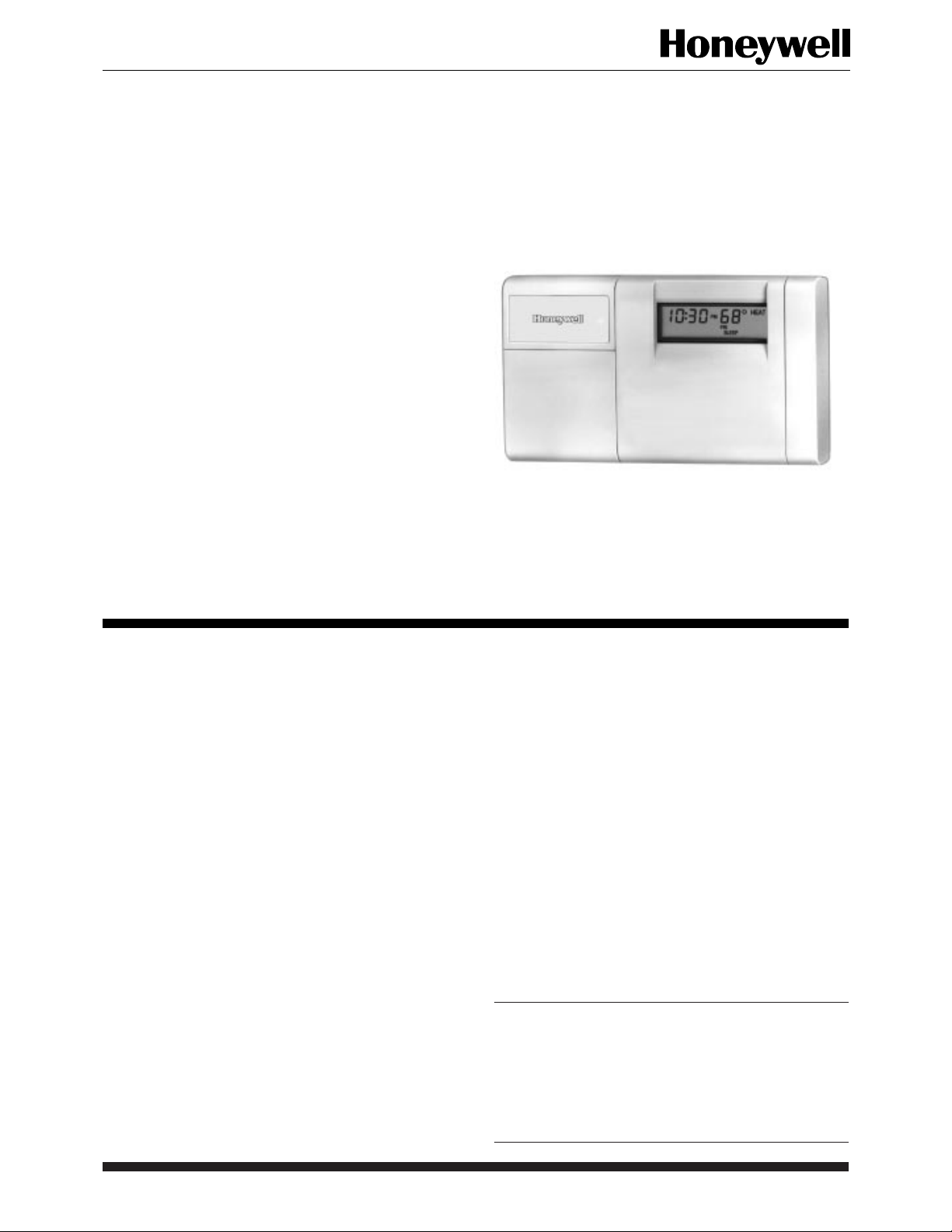
Programmable Thermostats
The T8131 and T8132 Thermostats provide
energy savings for single-stage heating and cooling applications while providing reliable, precise
temperature control.
T8131C
T8132C
T8131/T8132 Models
■ HEAT-OFF-COOL system switch.
■ AUTO-ON fan switch.
■ Separate programs for weekdays and weekends
5 day/2 day.
■ Digital LCD display.
■ Easy to program and install.
■ Precise temperature control.
■ Four daily energy saving programs.
■ Available in taupe and Premier White
■ Compatible with most 24 Vac standing pilot, gas
electronic ignition, oil or central electric systems.
™
.
T8131 Models Only
■ Powered directly from 24 Vac system transformer.
■ Green light emitting diode (LED) lights when prop-
erly connected.
■ Two AA alkaline batteries for backup power
recommended.
T8132 Models Only
■ Requires two AA alkaline batteries.
■ LCD flashes “bAt Lo” indicating low battery power.
■ Isolated heating/cooling circuits.
CONTENTS
Specifications ................................................ 2
Ordering Information.................................... 2
Installation .................................................... 3
Programming the Thermostat ....................... 8
Checkout and Settings ................................. 10
Troubleshooting .......................................... 11
Cross Reference .......................................... 12
1 68-0148—1 B.M. • Rev. 6-94 • ©Honeywell Inc. 1994 • Form Number 68-0148—1
Page 2
T8131A,B,C; T8132A,B,C
SPECIFICATIONS • ORDERING INFORMATION
Specifications
IMPORTANT: The specifications given in this publica-
tion do not include normal manufacturing tolerances; therefore, an individual unit may not exactly
match the listed specifications. Also, this product is
tested and calibrated under closely controlled conditions, and some minor differences in performance
can be expected if those conditions are changed.
MODELS:
T8131A/T8132A Programmable Thermostats: Provide
eight program keys; with keyboard door.
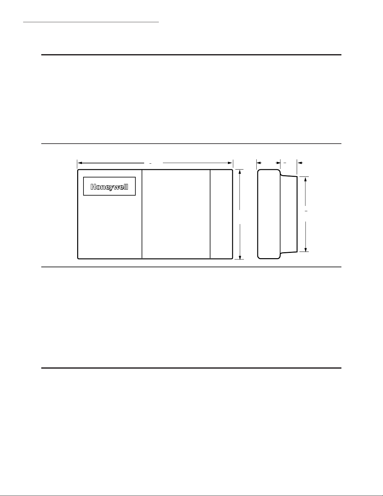
Fig. 1—Dimensions in in. [mm] of T8131 and T8132 models.
7
6 [175]
8
T8131B/T8132B Programmable Thermostats: Provide
eight program keys; without keyboard door.
T8131C/T8132C Programmable Thermostats: Deluxe
models, provide twelve program keys including usage key; with keyboard door.
ELECTRICAL RATING: T8131: 24 Vac.
T8132: Battery operated (2 AA alkaline batteries).
SYSTEM AND FAN RATINGS:
1.2A run; 7.5A inrush.
Total cooling and fan load not to exceed 1.2A.
DIMENSIONS: See Fig. 1.
3
[19]
4
1
1
4
[32]
4
[102]
1 [25]
M9349
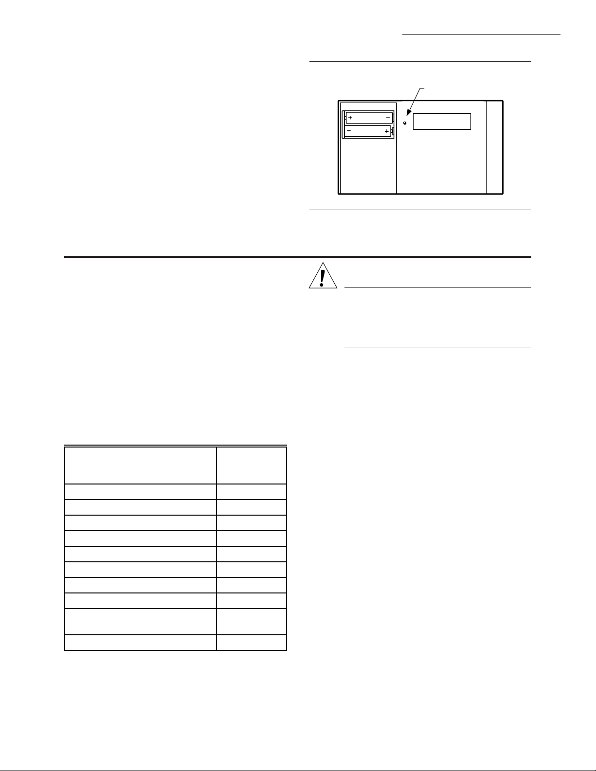
MOUNTING MEANS: Position mounting plate directly
on wall using two mounting screws and wall anchors
provided (See Fig. 2).
LIGHT EMITTING DIODE (LED): One LED on T8131
models only; lights to indicate proper operation when
both sides of the 24 Vac system transformer are prop-
erly connected. See Fig. 2 for position of LED.
OPERATING AMBIENT TEMPERATURE RANGE:
40° F to 110° F [4° C to 43° C].
SHIPPING TEMPERATURE RANGE: -20° F to 120° F
[-29° C to -49° C].
OPERATING RELATIVE HUMIDITY: 5 percent RH to
90 percent RH; noncondensing.
TIME INDICATION: 12 hour with AM, PM indication.
SET POINT RANGE: 45° F to 88° F [7° C to 31° C].
Ordering Information
When purchasing replacement and modernization products form your TRADELINE® wholesaler or your distributor, refer to the
TRADELINE Catalog or price sheets for complete ordering information, or specify—
1. Order Number.
2. Accessories, if desired.
If you have additional questions, need further information, or would like to comment on our products or services, please write or phone:
1. Your local Honeywell Home and Building Control Sales Office (check white pages of phone directory).
2. Home and Building Control Customer Satisfaction
Honeywell Inc., 1985 Douglas Drive North
Minneapolis, Minnesota 554212-4386 (612) 951-1000.
In Canada—Honeywell Controls Limited/Honeywell Limitée, 740 Ellesmere Road, Scarborough, Ontario M1P 2V9 . International
Sales and Service offices in all principal cities of the world. Manufacturing in Australia, Canada, Finland, France, Germany, Japan,
Mexico, Netherlands, Spain, Taiwan, United Kingdom, U.S.A.
68-0148—1 2
Page 3
CYCLES PER HOUR ADJUSTMENT:
Heating: Field adjustable to 3, 6, or 9 cph ±10 percent.
Cooling: Factory-set at 3 cph ±10 percent (not field
adjustable).
CALIBRATION: Thermostat and thermometer self-cali-
brating to ±1.25° F.
FINISH: All models available in taupe and Premier White™.
ACCESSORIES:
205013 Isolation Relay kit.
205014 Transformer Plug-in Kit.
205015 International Organization for Standardization
Relay and Transformer.
WHEN INSTALLING THIS PRODUCT…
1. Read these instructions carefully. Failure to follow
instructions can damage product or cause a hazardous
condition.
2. Check the ratings given in the instructions and on the
product and the compatibility chart below to make sure the
product is suitable for your application.
3. Make sure installer is a trained, experienced service
technician.
4. After completing installation, use these instructions
to check out product operation.
COMPATIBILITY
Check Table 1 to make sure the thermostat is compatible
with the intended system.
TABLE 1—COMPATIBILITY CHART.
Compatible
with
System Type
T8131/T8132
Gas—Standing Pilot Yes
Gas—Electronic Ignition Yes
Gas-Fired Boilers Yes
a
Gas—Millivolt No
Oil-Fired Boilers Yes
a
Oil-Fired Furnace Yes
Electric Furnace Yes
Electric Air Conditioning Yes
Baseboard Electric
No
(120/240 Line Volt)
Heat pumps/Multistage Equipment No
T8131A,B,C; T8132A,B,C
SPECIFICATIONS • INSTALLATION
Fig. 2—T8131 LED.
LED LIGHTS WHEN
PROPERLY CONNECTED
POWER
M9365
Installation
WARNING
ELECTROCUTION HAZARD CAN
CAUSE PROPERTY DAMAGE, SEVERE
INJURY, OR DEATH.
Disconnect power supply before wiring to prevent electrical shock or equipment damage.
LOCATION
Locate the thermostat about 5 ft [1.5m] above the floor
in an area with good air circulation at average temperature.
Do not mount the thermostat where it may be affected by:
—drafts or dead spots behind doors and in corners.
—hot or cold air ducts.
—concealed pipes and chimneys.
— unheated (uncooled) areas such as an outside wall
behind the thermostat.
MOUNT THERMOSTAT MOUNTING PLATE
(FIG. 2)
Position mounting plate on wall. Use spirit level to make
sure mounting plate is level. Use a pencil to mark the two
mounting holes.
Level for appearance only; thermostat will function
properly even when not level. Tighten mounting screws.
Remove mounting plate from wall, and drill 3/16 inch
holes in wall (if drywall) as marked. For firmer material
such as plaster or wood, drill 7/32 inch holes. Gently tap
anchors (provided) into drilled holes until flush with the
wall.
Reposition mounting plate over holes, pulling wires
through wiring opening. Loosely insert two mounting
screws into holes.
Not compatible with any 120/240 volt circuit.
Not designed for steam or gravity systems.
a
Compatible with 2-wire Honeywell zone valves. Isolating
relay required for 3-wire thermostats for zone valves. Not
compatible with 2-wire White Rodgers no. 1361 Valves.
3 68-0148—1
Page 4
T8131A,B,C; T8132A,B,C
INSTALLATION
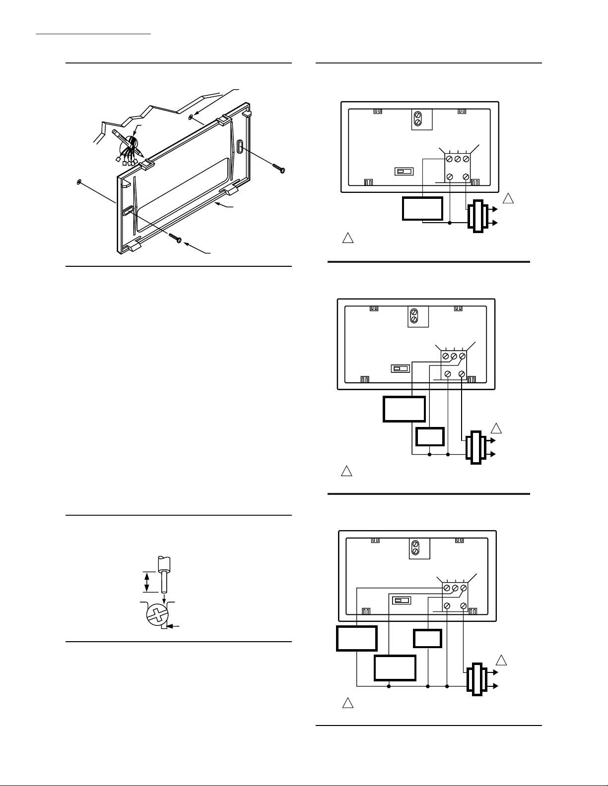
Fig. 3—Mounting thermostat mounting plate.
WALL
ANCHORS (2)
WIRES THROUGH
WALL OPENING
WALL
MOUNTING
PLATE
MOUNTING
SCREWS (2)
M1718
WIRING
All wiring must comply with all applicable electrical
codes, ordinances, and regulations. Follow instructions
provided with the controlled equipment.
Loosen the terminal screws and slip each wire beneath
its matching terminal. See Fig. 4 for wiring insertion techniques. Tighten terminals securely.
Plug the hole in the wall with insulation to help prevent
drafts from adversely affecting thermostat operation.
T8131 Models
Run the required number of wires to the thermostat
location (check the appropriate wiring diagram). Refer to
Figs. 5 through 7 for typical wiring diagrams.
T8132 Models
Run the required number of wires to the thermostat
location (check the appropriate wiring diagram). Refer to
Figs. 8 through 11 for typical wiring diagrams.
In 5-wire installations only, be sure to remove the factory-installed jumper connecting terminals R and Rc.
Fig. 4—Proper wiring technique.
PROPER WIRING TECHNIQUE
INSERT
5/16 in.
[8 mm]
STRIP
STRAIGHT
UNDER
SCREW HEAD
Fig. 5—3-wire heat-only application.
3-WIRE HEAT-ONLY
A
B
W Y G
C
HEATING
RELAY OR
VALVE COIL
1
POWER SUPPLY. PROVIDE DISCONNECT MEANS
AND OVERLOAD PROTECTION AS REQUIRED.
Fig. 6—4-wire cool-only application.
4-WIRE COOL-ONLY
A
B
W Y G
C
COOLING
CONTACTOR
COIL
FAN
RELAY
1
POWER SUPPLY. PROVIDE DISCONNECT MEANS AND
OVERLOAD PROTECTION AS REQUIRED.
R
Fig. 7—5-wire heat/cool application.
5-WIRE HEAT/COOL
A
B
W Y G
C
R
1
L1
(HOT)
L2
M9213
1
L1
(HOT)
L2
M9212
R
END OF WIRE
VISIBLE HERE
M3825
68-0148—1 4
HEATING
RELAY OR
VALVE COIL
COOLING
CONTACTOR
COIL
1
POWER SUPPLY. PROVIDE DISCONNECT MEANS AND
OVERLOAD PROTECTION AS REQUIRED.
FAN
RELAY
1
L1
(HOT)
L2
M9214
Page 5

T8131A,B,C; T8132A,B,C
INSTALLATION
Fig. 8—2-wire heat-only application (jumper
intact).
2-WIRE HEAT-ONLY (JUMPER INTACT)
A C
B D
W Y G
R
HEATING
RELAY OR
VALVE COIL
1
POWER SUPPLY. PROVIDE DISCONNECT MEANS AND
OVERLOAD PROTECTION AS REQUIRED.
L1
(HOT)
L2
Rc
JUMPER
1
M1709B
Fig. 9—3-wire cool-only application (jumper
intact).
3-WIRE COOL-ONLY (JUMPER INTACT)
A C
B D
W Y G
JUMPER
R
Rc
Fig. 10—4-wire heat/cool application (jumper
intact).
4-WIRE HEAT/COOL (JUMPER INTACT)
A C
B D
W Y G
R
HEATING
RELAY OR
VALVE COIL
1
POWER SUPPLY. PROVIDE DISCONNECT MEANS AND
OVERLOAD PROTECTION AS REQUIRED.
COOLING
CONTACTOR
COIL
FAN
RELAY
Rc
L1
(HOT)
L2
JUMPER
M1710B
Fig. 11—5-wire heat/cool application (jumper
removed).
5-WIRE HEAT/COOL (JUMPER REMOVED)
A C
B D
W Y G
COOLING
CONTACTOR
COIL
FAN
RELAY
1
POWER SUPPLY. PROVIDE DISCONNECT MEANS AND
OVERLOAD PROTECTION AS REQUIRED.
L1
(HOT)
L2
M848A
R
HEATING
RELAY OR
VALVE COIL
COOLING
1 1
L1
(HOT)
L2
1
POWER SUPPLY. PROVIDE DISCONNECT MEANS AND
OVERLOAD PROTECTION AS REQUIRED.
CONTACTOR
COIL
FAN
RELAY
Rc
L1
(HOT)
L2
M1711B
5 68-0148—1
Page 6

T8131A,B,C; T8132A,B,C
INSTALLATION
ADJUST FAN OPERATION SWITCH, AS
REQUIRED
The thermostat fan operation switch, labeled FUEL
SWITCH (see Fig. 12) is factory-set in the “F” position.
This is the correct setting for most systems. If this system is
Fig. 12—T8131 and T8132 back.
T8131 THERMOSTAT BACK
FUEL SWITCH
F
A
B
E
ADJUST SCREWS THROUGH HOLES
TO SELECT OPERATION DESIRED
HEATING SYSTEM
WARM AIR
FURNACE
HOT WATER
BOILER
ELECTRIC
FURNACE
W Y G
C
A–IN
A–OUT
1 TURN
A–IN
B–IN
B–IN
B–OUT
1 TURN
FUEL SWITCH
POSITION
F
F
E
R
ADJUST SYSTEM ON-LENGTH, AS REQUIRED
The thermostat on-length is factory-set for a warm air,
gas or oil heating system. When installing it on another type
of system, adjust the on-length accordingly by setting screws
A and B on the back of the thermostat, using the heating
system table in Fig. 12 as a guide. To minimize room
temperature swings, optimize the on-length according to
the type of system. Adjusting the screw “out one turn”
means turning the screw approximately 360°, or about one
complete turn.
NOTE: These thermostats do not have a setting for steam/
gravity air. Cycles would not be long enough for accu-
rate temperature control.
NOTE: For condensing furnaces, follow manufacturer
instructions.
If you want a longer on-length, readjust the screws as
follows (refer to the heating system table in Fig. 12):
If on-length screws A,B
are adjusted to match
this system:
For longer on-length,
readjust screws A,B
to match this system:
Electric furnace Warm air furnace
Warm air furnace Hot water boiler
an electric heat system, set the switch to “E.” The “E”
setting will allow the fan to turn on immediately with the
heating or cooling in a system where the “G” terminal is
connected.
T8132 THERMOSTAT BACK
DISPLAY °F
DISPLAY °C
FUEL SWITCH
F
C–IN
C–OUT
1 TURN
A C
B D
E
ADJUST SCREWS THROUGH HOLES
TO SELECT OPERATION DESIRED
HEATING SYSTEM
WARM AIR
FURNACE
HOT WATER
BOILER
ELECTRIC
FURNACE
W Y G
R
A–IN
A–OUT
1 TURN
A–IN
B–IN
B–IN
B–OUT
1 TURN
FUEL SWITCH
POSITION
F
F
E
Rc
M9348
Use two AA alkaline batteries; nonalkaline batteries
will not last as long. We recommend Energizer batteries.
Make sure the thermostat is set to OFF position.
Use a coin to remove battery door (see Fig. 13).
Install the fresh batteries as shown, making sure positive
and negative terminals are oriented correctly (see Fig. 14).
Replace battery door.
T8132 Models
As the batteries are running low, a “bAt Lo” indicator
will flash for one to two months before batteries run out
completely. Replace the batteries as soon as possible after
the indicator starts flashing. If the batteries are not replaced
sometime during the flashing “bAt Lo” indicator, the indicator will eventually stop flashing. When the batteries are
almost completely dead, “bAt Lo” will stay on without
flashing to indicate the thermostat and heating/cooling
system have stopped working.
The thermostat will not function after the batteries are
completely dead, and the “bAt Lo” indicator will disappear,
leaving a completely blank display.
Press down on left ends of batteries to remove. If the
new batteries are inserted within 20-30 seconds of removing the old ones, the thermostat will not require reprogramming. However, if the display is blank, the batteries are
dead or incorrectly installed and the thermostat requires
reprogramming. See owner’s manual to reprogram.
INSTALL BATTERIES
IMPORTANT: All T8132 models require batteries for
programming and operation of the thermostat and
heating/cooling system. Batteries are optional for
T8131 models, but are recommended to retain program memory if ac power is lost.
68-0148—1 6
T8131 Models
When the batteries are running low, the LED will display
“bAtLo” only when 24 Vac is not present, indicated by an
unlit LED.
Page 7

IMPORTANT: Although the thermostat has a low battery
indicator, replace the batteries once a year to prevent the thermostat from losing time and program
due to lack of battery power.
Fig. 13—Removing the battery door.
T8131A,B,C; T8132A,B,C
INSTALLATION
Fig. 14—Installing position for batteries.
INSTALL TWO AA ALKALINE
BATTERIES AS SHOWN
REMOVING
BATTERY
DOOR
M1719C
Fig. 15—Mounting the thermostat on the subbase.
A.
ENGAGE TABS AT TOP OF
THERMOSTAT AND MOUNTING PLATE.
B.
PRESS LOWER EDGE
OF CASE TO LATCH.
M1713
MOUNTING THE THERMOSTAT
To mount the thermostat on the subbase, engage the tabs
at the top of the thermostat and mounting plate (see Fig. 14)
and then press the lower edge of the case to latch.
NOTE:
FOR T8131A, C AND
T8132A, C, SWING
OPEN COVER.
CHECK
OPERATION.
M9366
7 68-0148—1
Page 8

T8131A,B,C; T8132A,B,C
PROGRAMMING THE THERMOSTAT
Programming the Thermostat
T8131A AND T8132A MODELS
Set Current Time/Day
To set time, press and release Set Clock/Day once, then
press Ahead or Back until the current time displays. To set
day, press and release Set Clock/Day again, and then press
Ahead or Back until the current day displays; then press
Run Program.
Heating Program
With the system switch at HEAT, press and release Set
Schedule once. “WAKE,” Mon-Fri and “SET” appear on
the display.
Press Ahead or Back to program “WAKE” time and
Warmer or Cooler to program “WAKE” temperature for
Mon-Fri. Repeat this sequence for “LEAVE,” “RETURN,”
and “SLEEP.”
Press Set Schedule until “SA SU,” and “SET” appear
on the display. Then press Ahead or Back to program
“WAKE” time and Warmer or Cooler to program “WAKE”
temperature for Sat-Sun. Repeat this sequence for “SLEEP.”
Cooling Program
With the system switch at COOL, follow the same
instructions as for Heating Program section.
After programming, adjust the fan and system switches
as desired. Press and release Run Program to start the
program.
A Quick Guide for Operating or Making Changes
NOTE: System switch must be set to Heat or Cool to
perform the following.
To temporarily change the temperature for the current
period only, press Warmer or Cooler. The temperature
will cancel itself at the next scheduled change. To cancel
sooner, press Run Program.
To hold a temperature indefinitely, press Hold Temp
then Warmer or Cooler. To cancel, press Run Program.
To check current temperature setting, press Run Pro-
gram. (If using TEMPORARILY CHANGE or HOLD,
pressing this key will cancel the change.)
To check programs, press Set Schedule repeatedly to
see each time and temperature; then press Run Program.
To cancel a program, press Set Schedule until the
program to cancel shows; then press Ahead and Back
together.
To permanently change a program, repeat steps in Heating Program or Cooling Program section as applicable.
To Return to the normal program or the start program,
press Run Program.
T8131B AND T8132B MODELS
Set Current Time/Day
To set time, press and release Clock/Day once, then
press Time ▲ or ▼ until current time displays. To set day,
press and release Clock/Day again, and then press Time ▲
or ▼ until current day displays; then press Run Program.
Heating Program
With system switch at HEAT, press and release Sched-
ule once. “WAKE,” Mon-Fri and “SET” appear on the
display.
Press Time ▲ or ▼ to program “WAKE” time and
Temp ▲ or ▼ to program “WAKE” temperature for Mon-
Fri. Repeat this sequence for “LEAVE,” “RETURN,” and
“SLEEP.”
Press Schedule until “SAT SUN,” “WAKE” and “SET”
appear on the display. Then press Time ▲ or ▼ to program
“WAKE” time and Temp ▲ or ▼ to program “WAKE”
temperature for Sat-Sun. Repeat this sequence for “SLEEP.”
Cooling Program
With system switch at COOL, follow the same instruc-
tions as for Heating Program section.
After programming, adjust fan and system switches as
desired. Press and release Run Program to start the
program.
A Quick Guide for Operating or Making Changes
NOTE: System switch must be set to Heat or Cool to
perform the following.
To temporarily change the temperature for the current
period only, press Temp ▲ or ▼. The temporary indicator
will show on the display and will cancel itself at the next
scheduled change. To cancel sooner, press Run Program.
To hold a temperature indefinitely, press Hold Temp,
then Temp ▲ or ▼. To cancel, press Run Program.
To check current temperature setting, press Run Pro-
gram. (If using TEMPORARILY CHANGE or HOLD,
pressing this key will cancel the change.)
To check programs, press Schedule repeatedly to see
each time and temperature; then press Run Program.
To cancel a program, press Schedule until program to
cancel shows; then press Time ▲ and ▼ together.
To permanently change a program, repeat steps in Heat-
ing Program or Cooling Program section as applicable.
To Return to the normal program or the start program,
press Run Program.
68-0148—1 8
Page 9

T8131A,B,C; T8132A,B,C
PROGRAMMING THE THERMOSTAT
T8131C AND T8132C MODELS
Set Current Time/Day
To set time, press and release Set Clock/Day once, then
press Ahead or Back until current time displays. To set
day, press and release Set Clock/Day again, and then press
Ahead or Back until current day displays; then press Run
Program.
Heating Program
With system switch at HEAT, press and release Weekday Schedule once. “WAKE,” Mon-Fri and “SET” appear
on the display.
Press Ahead or Back to program “WAKE” time and
Warmer or Cooler to program “WAKE” temperature for
Mon-Fri. Repeat this sequence for “LEAVE,” “RETURN,”
and “SLEEP.”
Press Weekend Schedule until “SAT SUN,” “WAKE”
and “SET” appear on the display. Then press Ahead or
Back to program “WAKE” time and Warmer or Cooler to
program “WAKE” temperature for Sat-Sun. Repeat this
sequence for “SLEEP.”
Cooling Program
With system switch at COOL, follow the same instructions as for Heating Program section.
After programming, adjust fan and system switches as
desired. Press and release Run Program to start the
program.
A Quick Guide for Operating or Making Changes
NOTE: System switch must be set to Heat or Cool to
perform the following.
To temporarily change the temperature for the current
period only, press Warmer or Cooler. The temperature
will cancel itself at the next scheduled change. To cancel
sooner, press Run Program.
To hold a temperature indefinitely, press Hold Temp
then Warmer or Cooler. To cancel, press Run Program.
To check current temperature setting, press Present
Setting.
To check programs, press Weekday Schedule then
Weekend Schedule repeatedly to see each time and tem-
perature; then press Run Program.
To cancel a program, press Weekday Schedule then
Weekend Schedule until the program to cancel shows;
then press Clear.
To check usage, press Usage for the length of time heat
or air conditioning has been running today since midnight.
Press this key again for yesterday’s usage, and again for
cumulative usage. Press Clear to clear cumulative reading
if desired; then press Run Program.
To permanently change a program, repeat steps in Heating Program or Cooling Program section as applicable.
To Return to the normal program or the start program,
press Run Program.
9 68-0148—1
Page 10

T8131A,B,C; T8132A,B,C
CHECKOUT AND SETTINGS
Checkout and Settings
CHECKOUT
After the thermostat is mounted on the subbase, check operation as follows:
Heating A,C B
For T8131 models only, first check that the green power LED is lit, indicating the
thermostat is powered properly.
Do not check heating system operation by jumpering thermostat terminals at the
primary control, such as the gas valve, zone valve, or oil burner control. This will
damage the thermostat.
Move the system switch to HEAT and the fan switch to AUTO.
Press key until the setting is about 10° F [6° C] above room temperature. After a
short delay, heating should start and the fan should run (immediately if fan
operation switch is set in E position).
Press key until setting is about 10° F [6° C] below room temperature. The heating
equipment should shut off.
Model
HeatCool Off
Auto On
Temp
Warmer
Temp
Cooler
Cooling A,C B
For T8131 models only, before continuing check that the green LED is lit,
indicating the thermostat is powered properly.
To avoid possible compressor damage, do not operate the cooling system when
outside temperature is below 50° F [10° C]. See compressor manufacturer
HeatCool Off
instructions for further information.
NOTE: When cooling setting is changed, thermostat may delay up to five
Auto On
minutes before turning on the air conditioner to protect the compressor.
Move the system switch to COOL and the fan switch to AUTO.
Press key until setting is about 10° F [6° C] below room temperature. The cooling
equipment and fan should start
Press key until the setting is about 10° F [6° C] above room temperature. The
cooling equipment and fan should stop.
Move the system switch to OFF with the fan switch remaining at AUTO. The
system and fan should be off.
Cooler
Warmer
Auto On
Temp
Temp
HeatCool Off
68-0148—1 10
Page 11
CHECKOUT AND SETTINGS • TROUBLESHOOTING
SETTINGS AND ADJUSTMENTS
Set the Fan and System Switches
First set the fan switch FAN AUTO: Normal setting for most homes. A single-speed
fan will turn on automatically with the air conditioner or
furnace. A two-speed fan will usually run on high with the
air conditioner and on low with the furnace.
FAN ON: The fan runs continuously. Use for improved air
circulation during special occasions or for more efficient
electronic air cleaning.
Then set the system switch. COOL: The thermostat controls the air conditioning system.
T8131A,B,C; T8132A,B,C
Auto On
Auto On
HeatCool Off
OFF: Both the heating and air conditioning systems are off.
HEAT: The thermostat controls the heating system.
HeatCool Off
HeatCool Off
Troubleshooting
IF… THEN…
Display will not come on. T8131
• Check that green LED is lit.
T8132
• Set the system switch to OFF; remove batteries; insert backward for at least
five seconds to reset thermostat; replace batteries correctly. Display should
come on.
• Make sure batteries are fresh and installed correctly.
Temperature display will not go T8131/T8132
lower than 45° F [7° C] or higher • The temperature setting limit has been reached. The setting range is 45° F
than 88° F [31° C] during to 88° F [7° C to 31° C].
programming.
Heating will not come on. T8131
• Check that green LED is lit.
T8132
• If display is blank or says “bAt Lo,” install fresh batteries.
T8131/T8132
• Check that switch on thermostat is set to HEAT.
• Check the system fuse or circuit breaker and replace or reset if necessary.
• If temperature setting is higher than current temperature, and SYSTEM
ON indicator is lit, see furnace manufacturer instructions.
Cooling will not come on. T8131
• Check that green LED is lit.
T8132
• If display is blank or says “bAt Lo,” install fresh batteries.
• If 2- or 4-wire installation, verify that R-Rc jumper is installed.
T8131/T8132
• Check that switch on thermostat is set to COOL.
• Check the system fuse or circuit breaker and replace or reset if necessary.
• The thermostat has a built-in time delay on cooling. Allow five to ten min-
utes after changing the setting before the air conditioner starts.
• If temperature setting is lower than current temperature, and SYSTEM ON
indicator is lit, move system switch from COOL to OFF for ten minutes.
11 68-0148—1
Page 12

T8131A,B,C; T8132A,B,C
TROUBLESHOOTING • CROSS REFERENCE
Cooling will not come on (Continued). After ten minutes, return switch to COOL position. If air conditioner comes
SYSTEM ON indicator is lit, but • Allow time for the furnace to heat up and the fan to come
no heat is coming from the registers. on before checking for heat at the register. Check to make sure system on-
Furnace or air conditioner cycles • Check system setting on back of thermostat.
too frequently.
The system on-length • Readjust according to instructions on page 6.
is too short or too long.
The thermostat current setting does • Check that the wiring hole in the wall behind the wallplate has been plug-
not match the display temperature. ged with insulation to prevent drafts that might adversely affect thermostat
on, compressor may have reached its high limit temperature protection and
shut down. If air conditioner does not come on after the ten minutes and the
SYSTEM ON indicator is lit, see air conditioner manufacturer instructions.
length is set correctly according to instructions on page 6.
operation.
• Be aware that it is normal for the current setting and display temperature to
differ occasionally.
Cross Refer ence
T8131/T8132 CROSS REFERENCE CHART.
T8131/T8132
Model
Number Description
Trade
Replacement Remarks
T8131 models:
C1004 Honeywell logo; TRADELINE® model. T8131C1004
C1012
Honeywell logo; TRADELINE
®
model;
T8131C1012
Premier White™.
T8132 models:
A1007
Honeywell logo; Honeywell Canada
®
TRADELINE
model; configurable
T8132C1003 °F only.
for °F/°C.
T8132C1011 Replacement is Premier White™, °F only.
A1015
Carrier Weathermaker logo; Carrier part
T8132C1003
no. HH07AX017; Fixed 6CPH.
T8132C1011 Replacement is Premier White™.
A1023 Enerplus logo; configurable for °F/°C. T8132C1003 °F only.
T8132C1011 Replacement is Premier White™; °F only.
B1005
Zone Perfect logo; Carrier part
T8132C1003 Replacement has a keyboard door.
no. HH07AX016; Fixed 6 CPH.
T8132C1011 Replacement has a keyboard door and is
Premier White™.
C1003 Honeywell logo; TRADELINE® model. T8132C1003
C1011
Honeywell logo; TRADELINE
®
model;
T8132C1011
Premier White™.
Home and Building Control Home and Building Control Helping You Control Your World
Honeywell Inc. Honeywell Limited—Honeywell Limitée
1985 Douglas Drive North 740 Ellesmere Road
Golden Valley, MN 55422 Scarborough, Ontario
M1P 2V9
68-0148—1 12
Printed in U.S.A.
QUALITY IS KEY
 Loading...