

Page 1

Zone Thermostat
Heating/Cooling Thermostat and
Subbase or W allplate
Model T8090T
OWNER’S MANUAL
69-0432-1
Page 2

Welcome to the world of energy savings with your new Honeywell Trol-A-Temp Zone
®
Thermostat.
Your new thermostat will automatically control the temperature in your home to provide a high
level of comfort plus energy savings when programmed according to the instructions in this
manual.
With zone control, you heat or cool each zone or living area only when needed. The independent control of each zone provides additional energy savings.
Recycling Notice
This control contains mercury in a sealed tube. Do
M3375
not
place control in the trash at the end of
its useful life.
If this control is replacing a control that contains mercury in a sealed tube, do
not
place your
old control in the trash.
Contact your local waste management authority for instructions regarding recycling and the
proper disposal of the control, or of an old control containing mercury in a sealed tube.
If you have questions, call Honeywell Inc. at 1-800-468-1502.
2 69-0432—1
Page 3

Table of Contents
PAGE
Features of Your Thermostat ............................................................................................................ 4
Setting the Temperature ................................................................................................................... 7
Inserting Clock Batteries ................................................................................................................... 8
Setting the Clock ............................................................................................................................... 9
Programming................................................................................................................................... 11
Troubleshooting .............................................................................................................................. 15
Servicing the Thermostat ................................................................................................................ 21
Heat Anticipator Setting .............................................................................................................. 21
Thermometer Adjustment............................................................................................................ 22
3 69-0432—1
Page 4
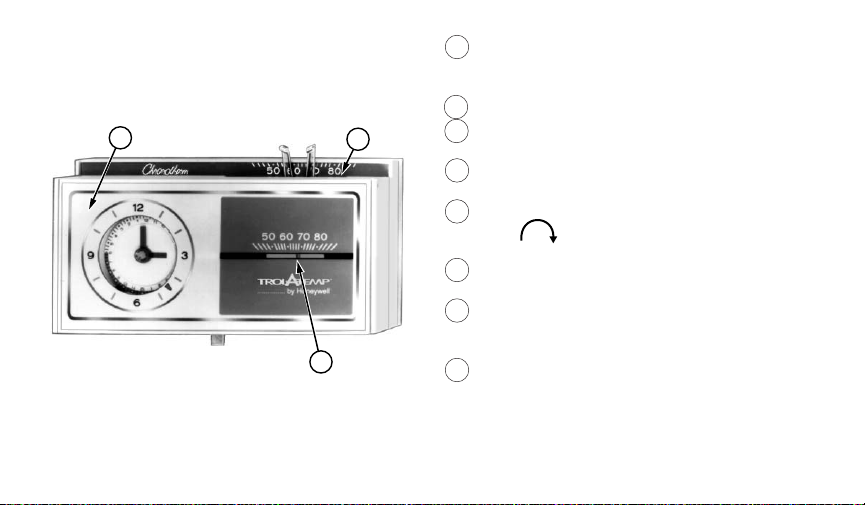
Features of Your
Thermostat
1
1 FLIP-UP COVER. Lift it up to set clock for
energy savings and normal temperature
periods.
2 THERMOSTAT COVER.
2
3 THERMOMETER. Provides accurate room
temperature reading.
4 CLOCK. This clock provides a 24-hour
slotted dial to hold the programming pins.
5 CLOCK HANDS. Turn minute hand clock-
wise to match the correct AM or PM
time to the time indicator.
6 TIME INDICATOR. Arrow head indicates
time for 24-hour dial.
7 PROGRAM INDEX WHEEL. Controls high
M8693
3
and low temperature at specific time of
day as set by program pins.
8 TEMPERATURE SETTING LEVERS. Left
(blue mark) controls the low temperature;
right (red mark) controls the high temperature.
4 69-0432—1
Page 5
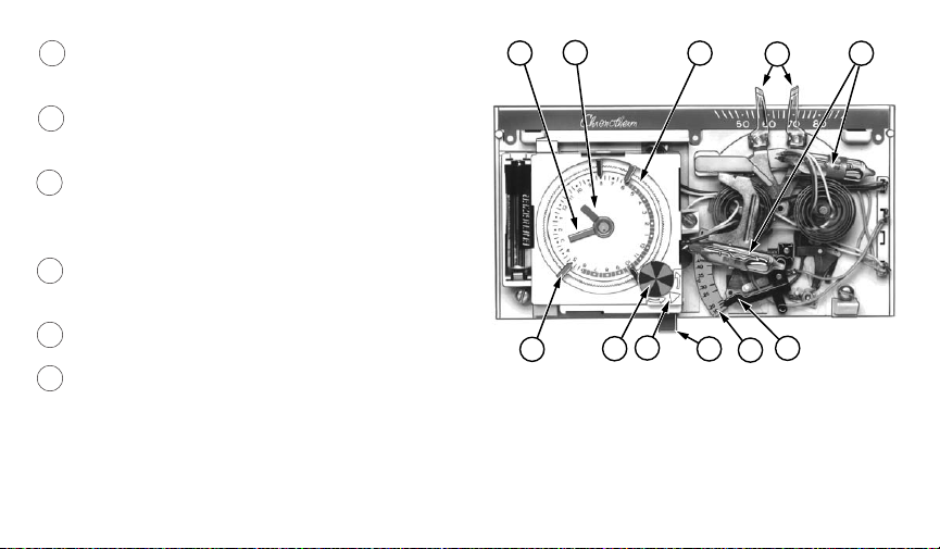
9 PROGRAM PINS. Must be inserted into
24-hour clock dial slots to control program
index wheel.
10 PIN SLOTS. Located on 24-hour dial at
10-minute intervals for program pin
insertion.
11 MANUAL PROGRAM ADVANCE BUTTON.
Allows change from comfort to energy
savings setting and vice versa without
changing the program.
12 HEAT ANTICIPATOR SCALEPLATE.
Calibrated to match the heating system
current draw in amperes.
13 ANTICIPATOR SETTING LEVER. Must be
set at 0.1A for proper system operation.
14 MERCURY BULB AND BIMETAL
ELEMENT(2). Provide automatic temperature control by switching the heating or
cooling system on and off.
5
4
9
7
10
6
11
8
13
12
14
M8691
5 69-0432—1
Page 6
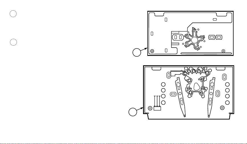
15 WALLPLATE
Provides mounting base and wiring connections for control of zones other than
zone 1 in heating or heating-cooling
systems.
16 SUBBASE
Provides mounting base, wiring connections and manual switching for control of
zone 1 in heating or heating-cooling
systems.
15
M2421
W
G
16
Y
R
M8690
6 69-0432—1
Page 7
Setting The Temperature
For Heating:
■ Set the left lever (blue mark) to the energy
savings temperature you want when you are
sleeping or the associated zone is unoccu-
pied.
■ Set the right lever (red mark) to the temp-
erature you want for normal comfort
periods.
NOTE: You may override the time program by
setting both the red and blue levers to the
same temperature setpoint.
For Cooling:
■ Set the left lever (blue mark) to the tempera-
ture you want for normal comfort periods.
■ Set the right lever (red mark) to the energy
savings temperature you want when you are
sleeping or the associated zone is unoccu-
pied.
LOW TEMPERATURE
SETTING LEVER
(BLUE MARK)
12
8
7
9
6
0
1
5
4
11
2
3
1
1
9
2
2
3
1
1
3
2
11
4
10
5
6
9
7
8
6
50
607080
50
60 70 80
by Honeywell
HIGH
TEMPERATURE
SETTING
LEVER
(RED MARK)
M641A
Fig. 1—Setting high and low
temperature setting levers.
7 69-0432—1
Page 8
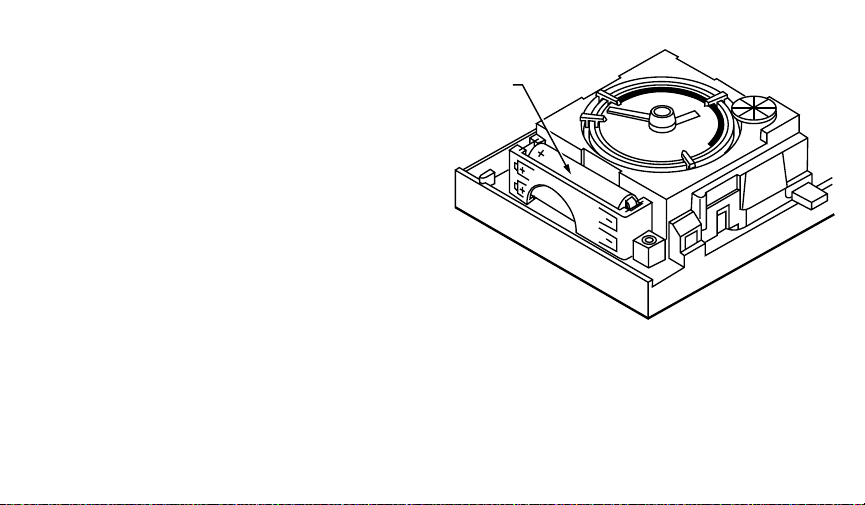
Inserting Clock
Batteries
Power is supplied to the clock by two AAA
alkaline batteries (included). Install batteries in
thermostat as shown in Fig. 2. Once a year or
when batteries are dead, replace with two new
AAA alkaline batteries. We recommend
Energizer
®
batteries.
BATTERY LOCATION FOR
(2) AAA BATTERIES;
INSTALL WITH POSITIVE
ENDS UP
M7188
Fig. 2—Inserting clock batteries.
8 69-0432—1
Page 9

Setting the Clock
Lift thermostat flip-up cover and you’ll find
the 24-hour program dial, slotted in 10-minute
increments. Adjust the clock to the current time
by moving the minute hand carefully in a clockwise direction. DO NOT reverse the
minute hand.
When time is correctly set, the time indicator
arrow (see Fig. 3) will point to the correct time
and corresponding daytime (light) or nighttime
(dark) band of the program dial.
MINUTE
HAND
TIME
INDICATOR
ARROW
EXAMPLE: For 11 PM, the time indicator arrow
will point directly to the dark band. For 11 AM ,
the arrow will point to them light band on the
dial.
M8561
Fig. 3—Setting the clock.
9 69-0432—1
Page 10

Daylight Savings Time
When Daylight Savings Time starts, move the minute hand carefully in a clockwise
direction one hour. When Daylight Savings Time ends, move the minute hand carefully in a
clockwise direction 23 hours. Do NOT reverse the minute hand, or damage to the
timer mechanism may occur.
10 69-0432—1
Page 11

Programming
You can program your thermostat to
automatically lower and raise the temperature
one or more times every 24 hours.
Before setting your program
■ To insert a pin, push it straight into the
selected notch on the program dial until it is
completely seated.
■ Lift thermostat flip-up cover and you’ll find
the 24-hour program dial. The slots on the
program dial (Fig. 4) are for the program
pins, which can be inserted at 10-minute
intervals.
■ Three red and three blue program pins are
included with your thermostat. The red pins
start the high-temperature period; the blue
pins start the low-temperature period. A
heating program is preprogrammed. A red
24-HOUR PROGRAM DIAL
(GRAY AREA FOR
NIGHT SETTINGS
FLIP-UP
COVER
PROGRAM
PINS
THERMOSTAT
COVER
PROGRAM PIN SLOT
PROGRAM INDEX WHEEL
MANUAL PROGRAM
ADVANCE BUTTON
PROGRAM PIN
STORAGE
TIME INDICATOR
ARROW
M8692
Fig. 4—Program components.
11 69-0432—1
Page 12

pin is inserted at 6:00 AM for high temperature (comfort period); a blue pin is inserted at 10:00
PM for low temperature (energy saving period). Two additional sets of pins are located in the
program pin storage area. You can set up to six temperature changes with the pins supplied.
We recomment at least five hours for each energy saving period.
■ To change the pins add a new energy saving period.
■ To remove a pin, press against the program dial and pull the pin straight out. DO NOT attempt
to change a pin if it is engaged with the program index wheel.
■ On heating/cooling systems, be sure to reset the pins when the seasons change. You will also
probably want to change the lever positions.
12 69-0432—1
Page 13

Setting the Heating Program
■ Decide when you want the temperature to reach the comfort level. Find the notch on the dial
that is one-half hour before this time and insert a
furnace time to heat the house before you wake up or arrive home.
■ Decide when you want the energy
saving period to start and insert a
blue
pin at the notch that corresponds to this time. After the blue
pin engages, the furnace will be off
until room temperature drops to the
energy saving setpoint.
■ You can set both a day and a night
program. See Fig. 5 for program
examples.
NIGHT
ENERGY
SAVING
PERIOD
DAY
ENERGY
SAVING
PERIOD
red
pin. The half-hour head start gives the
WINTER SUMMER
BEGINS
10:00 PM
ENDS
6:00 AM
BEGINS
7:30 AM
ENDS
4:00 PM
TEMPERATURE
°F
°C
58
14
68
20
58
14
68
20
PROGRAM
PIN IN
CONTROL
BLUE
RED
BLUE
RED
TEMPERATURE
°F
80
75
80
75
°C
27
24
27
24
PROGRAM
PIN IN
CONTROL
RED
BLUE
RED
BLUE
M626A
Fig. 5—Programming examples.
13 69-0432—1
Page 14

Setting the Cooling Program
■ Decide when you want the temperature to reach the comfort level. Find the notch on the dial
that is one-half hour before this time and insert a
air conditioner time to cool the house before you wake up or arrive home.
■ Decide when you want the energy saving period to start and insert a
corresponds to this time. After the red pin engages, the air conditioner will be off until the room
temperature rises to the energy saving setpoint.
blue
pin. The half-hour head start gives the
red
pin at the notch that
Start or End Programs With Manual Program Advance Button
To prevent damage to the program advance mechanism, DO NOT use the program
advance button within a 30-minute period before or after a program change.
The manual program advance button enables immediate, one-time-only program changes to
accommodate temporary schedule changes.
Press the button to immediately begin an energy saving period or return to the normal setting.
After pressing the button, check the program indicator to assure the system is in the desired
mode. If the program indicator shows blue, the lower temperature is in effect; if the program
indicator shows red, the higher temperature is in effect. Using the manual advance button will not
affect the stored program.
IMPORTANT
14 69-0432—1
Page 15

Troubleshooting
Your Honeywell Trol-A-Temp® Thermostat requires little or no attention. Most problems can be
traced to the following.
PROBLEM CHECK ACTION
No heat. —system switch. May be in OFF or
COOL position.
—fuse or circuit breaker. If blown or tripped, replace fuse or
—furnace power switch. May be Off. Move switch to ON.
—heating equipment for proper
operation.
—thermostat connections. Turn Off power. Check for correct
—airflow at register. Zone damper
may be closed.
1
15 69-0432—1
Move system switch to HEAT
position.
reset breaker.
See manufacturer’s instructions.
terminal hookups. Repair any frayed
or broken wires. Firmly tighten all
terminal screws.
If damper is closed, contact a
qualified service technician for
assistance.
(continued)
Page 16

Troubleshooting (continued)
PROBLEM CHECK ACTION
No heat. —other. Contact a qualified service technicial
for assistance.
Energy saving
temperature program
—program dial for proper day or
night phase.
Turn clock ahead 12 hours. Move
minute hand clockwise only.
12 hours off.
Rooms do not warm
up at programmed
time.
Temperature change
occurs at the wrong
—timer program for heating system.
May need more time to warm up
rooms.
—program pins for correct time
locations.
Move red pin one-half hour earlier on
the program dial.
Relocate pins to desired settings.
time.
Room temperatures
are not correct.
—positions of thermostat setpoint
levers.
—position of subbase system
Reset to desired temperatures.
Move to desired operating position.
switch. 1
—air flow at register. Damper may be operating improperly.
Contact a qualified service technician
for assistance.
(continued)
16 69-0432—1
Page 17

Troubleshooting (continued)
PROBLEM CHECK ACTION
Room temperatures
are not correct.
—thermostat circuits. HEATING—Make sure zone 1 sy-
stem switch is set at HEAT and fan
switch is set at AUTO. Move temperature setting levers on the appropriate zone thermostat 5° F [3° C]
above room temperature. Heating
should start; damper should be open.
COOLING—Make sure zone 1
system switch is set at COOL and fan
switch is set at AUTO. Move temperature setting levers on the
appropriate zone thermostat 5° F
[3° C] below room temperature.
Cooling should start; damper should
open. IF SYSTEMS DO NOT
OPERATE, CONTACT A QUALIFIED
SERVICE TECHNICIAN.
17 69-0432—1
(continued)
Page 18

Troubleshooting (continued)
PROBLEM CHECK ACTION
No cooling. 2 —system switch. May be in OFF or
Move switch to COOL position.
HEAT position. 1
—fuse or circuit breaker. If fuse is blown or breaker tripped,
replace or reset.
—condenser switch position.
Move to ON position.
Located outdoors and may be
turned Off.
—cooling equipment for proper
See manufacturer instructions.
operation.
—thermostat connections. Turn Off power. Check for correct
terminal hookups. Repair any frayed
or broken wires. Firmly tighten all
terminal screws.
—airflow at register. Zone damper
may be closed.
If damper is closed, contact a
qualified service technician for
assistance.
—other. Contact a qualified service technician
for assistance.
18 69-0432—1
(continued)
Page 19

Troubleshooting (continued)
PROBLEM CHECK ACTION
Clock does not run. —voltage across the C and R
terminals.
Remove thermostat from the wall-
plate or subbase, and measure the
voltage. Refer to page 20 for cause
and action.
Thermostat setting
and thermometer
—level position of thermostat. Reinstall thermostat wallplate or
subbase. Use a spirit level.
reading disagree.
—area around thermostat for drafts
or radiant heat.
Thermostat should be about 5 ft
[1.5m] above floor on an inside wall.
Contact qualified service technician
for change of location.
—calibration of thermometer. See instructions on page 22.
1 Applicable on zone 1 thermostat only.
2 Not applicable on heating-only system.
If this Troubleshooting section has not solved the problem, call a qualified Trol-A-Temp
customer service at or service technician, 1-800-828-8367 for additional assistance.
19 69-0432—1
®
Page 20

Voltage at Clock Terminals
AC VOLTAGE AT
C-R TERMINALS
0 Vac 1. System power is Off. 1. Restore power.
2. Short in clock power supply wiring. 2. Replace wiring.
3. Limit switch contacts stuck open. 3. Free or replace limit switch.
4. Transformer supplying power is
Up to 15 Vac. 1. System transformer used to power
2. Additional (separate) transformer
15 to 30 Vac. 1. Spring fingers on thermostat are
2. Clock has failed. 2. Replace the thermostat.
POSSIBLE CAUSE
CHECK ACTION
burned out.
the clock is inadequate.
used to power the clock has
inadequate voltage.
not making proper contact with the
subbase terminals.
20 69-0432—1
4. Replace transformer.
1. Use additional (separate)
transformer.
2. Install transformer with proper
secondary voltage.
1. Rebend spring fingers to a 45
degree angle to assure proper
contact.
Page 21

Servicing the Thermostat
Heat Anticipator Setting
The T8090T Thermostat has an adjustable
heat anticipator that was factory-set at 0.1A.
The heat anticipator must be set at 0.1A for
proper system operation. See Fig. 6.
MOVE
INDICATOR
TO 0.1A
M8596
Fig. 6—Heat anticipator setting.
21 69-0432—1
Page 22

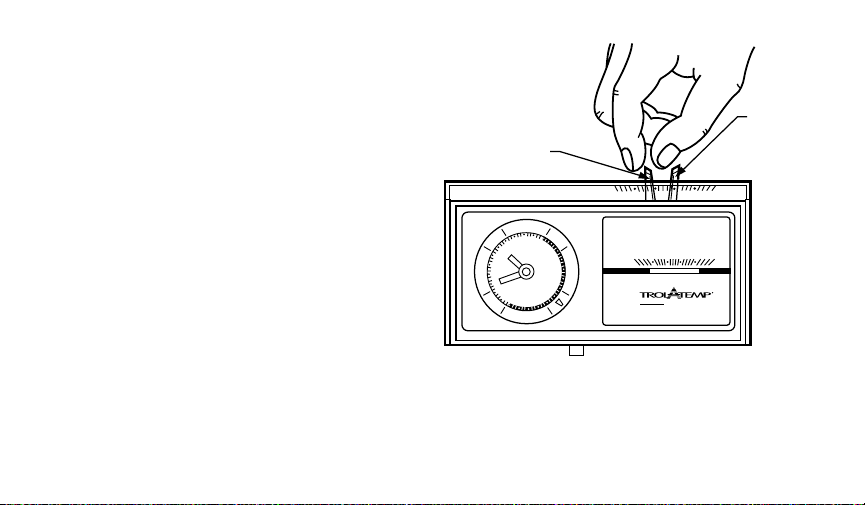
Thermometer Adjustment
The thermometer was accurately calibrated at the factory and should only need adjustment if it
was dropped or mishandled.
If the setpoint lever and the thermometer reading do not agree, follow the procedure below.
Remove the thermostat cover and open the flip-up cover.
Set the thermostat cover on a table near a thermometer of known accuracy.
Allow at least five minutes for the cover
thermometer to sense the area temperature; then compare the readings. Be careful
THERMOMETER
SLOT
BACKSIDE OF
FLIP-UP COVER
not to touch the thermometer or breathe on
it.
If the readings are the same, replace the
cover and put the system into operation.
INSERT AND TURN
SCREWDRIVER
If the readings are different, insert a
small screwdriver in the thermometer slot,
shown in Fig. 7, and turn it until both
thermometers read the same.
Replace thermostat cover and put the
system into operation.
M1810
Fig. 7—Thermometer adjustment.
22 69-0432—1
Page 23

If you have questions regarding the installation and programming of your Honeywell Trol-A-
®
Thermostat, please contact a Trol-A-Temp® customer servoce re[resentative at 1-800-
Temp
828-8367. Before you call, please have the following information available: Make and model of
your furnace, old thermostat and air conditioner.
23 69-0432—1
Page 24

Home and Building Control Home and Building Control Helping You Control Your World
Honeywell Inc. Honeywell Limited—Honeywell Limitée
1985 Douglas Drive No. 740 Ellesmere Road
Golden Valley, MN 55422 Scarborough, Ontario
M1P 2V9
D.F. ©Honeywell Inc. 1995 Printed in Mexico Rev. 1-95 Form Number 69-0432—1
M3375
 Loading...