

Page 1
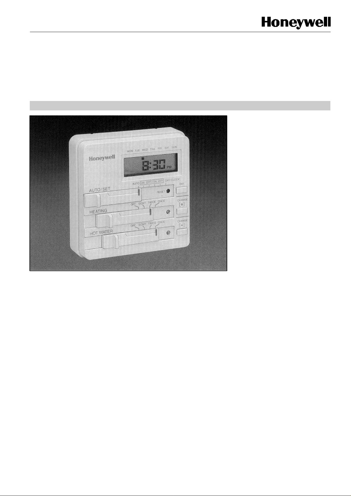
ST799
The ST799 electronic dual zone timer
with two ON/OFF periods per day.
FEATURES
•
Wallplate compatibility with 24-hour version (ST699)
ELECTRONIC DUAL
ZONE TIMER
PRODUCT DATA
is used to control gravity, primary or
fully pumped central heating systems
requiring a single 7-day programme
ST799 incorporates a simple and
intuitive programming concept which
established the 24-hour version
(ST699) as the leading electronic dual
zone timer on the market.
ST799 is designed for European CEN
approval.
• 7-day programme
• Weekday/weekend programme option (installer link)
• Independent heating and hot water channels
• One or Two ON/OFF periods per day
• Built-in programme
• Temporary programme override/advance
• 7-day battery back-up
• Compact size
• AM/PM or 24 hour clock format (factory option)
• 10 minute programme resolution
• 3 A resistive/inductive (@ 0.6 pf) 230 V~ SPDT relay
rating
• Simple/intuitive programming concept
• Copy day feature
• Surface or wallbox mounting options
• Pack contains everything for immediate installation
EN0R 8440 R0
Page 2
ST799 ELECTRONIC DUAL ZONE TIMER
DIMENSIONS
INSTALLATION
SPECIFICATIONS
Product type
: Electronic dual zone timer
Programme day
: 03.00 AM to 02.50 AM (on the next day)
Wiring
: Surface or single
wallbox (UA1 size)
Protection class
ORDERING SPECIFICATION
Power supply : 230 V~ (±10%), 50 HZ
Power reserve : Rechargeable battery with 7 days
backup following a 24 hour charging
period
Switch rating : 2 x SPDT potential free
3 A resistive @ 230 V~ (± 10%), 50 Hz
3 A inductive @ 0.6 pf
Programme : 7-day with two ON/OFF periods daily
5/2-day (weekday/weekend) option by
installer link
Programme
resolution
Override : Advance next programme time
: 10 minutes
(change)
Wiring access : Rear or bottom edge (surface wiring
access)
Wire gauge : 0.75 to 2.5 mm2 two max. per terminal
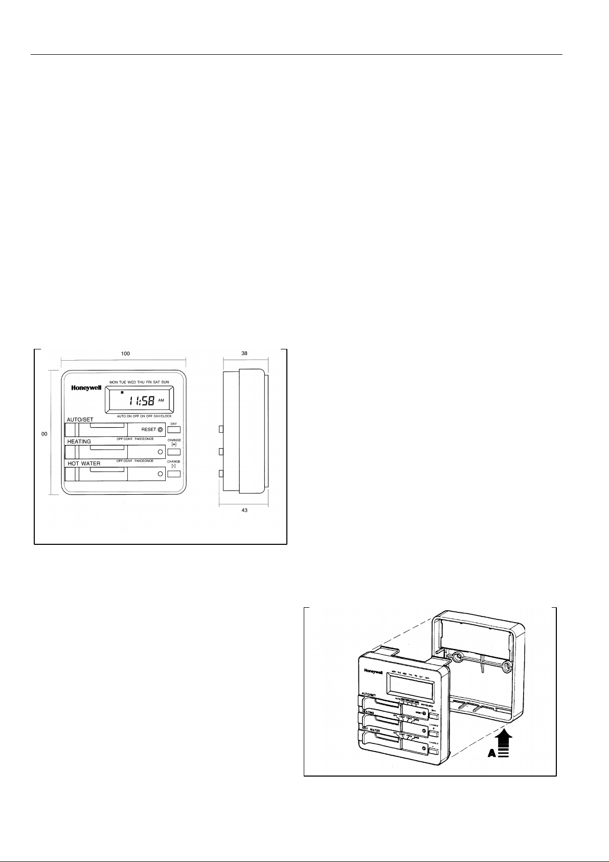
Dimensions : 100 x 100 x 38 mm (w x h x d)
: IP20 (IEC 529)
Environmental : Operating temperature range 0 to 45oC
Shipping and storage temperature
range -20 to 55oC
Humidity range 0 to 90% rh, non-
condensing
Approvals : Designed to meet European CEN
approval EN60730
Life : 7 years minimum
ST799A1003
100
Mounting
Remove the subbase from the timer by depressing the
securing clip A and pulling the two halves apart. See fig. 1
The ST799 can either be mounted onto the wall surface or a
flush mounted UA1 (with 60.3 mm pitch mounting holes)
using the screws supplied.
Weekday/Weekend Programme
To convert timer from 7-day programme to 5+2 day
(Weekday/Weekend) programme, cut and remove link LK1
on the main circuit board.
IMPORTANT
1. The installer must be a trained service
engineer
2. Disconnect the power supply before beginning
installation
EN0R 8440 R0 2
Fig. 1
Page 3
ST799 ELECTRONIC DUAL ZONE TIMER
WIRING
wired in accordance with the latest IEE wiring regulations.
CLOCK
CLOCK
CLOCK
CLOCK
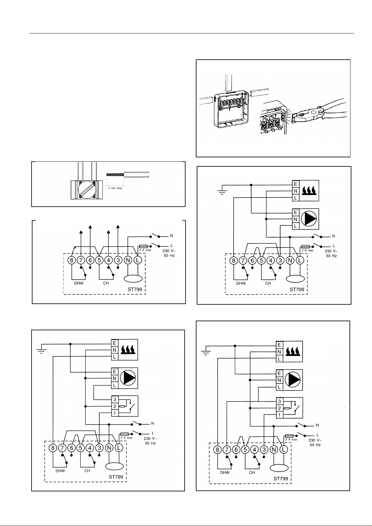
Cable entries can be made through the opening in the rear of
the subbase, or via the three surface entry break-outs in the
top and two sides of the wallplate. See fig. 2
The ST799 is designed for fixed wiring only and must be
Ensure the wiring connections to the mains supply is via a
fuse rated at not more than 3 A and a Class "A" switch
(having contact separation of at least 3 mm in all poles).
Remove the terminal cover to allow access to the wiring
terminals as shown in fig.2. Connect the systems wiring as
shown by the specific applications wiring diagram. A
maximum of two 2.5 mm2 (cross sectional area) wires can be
connected to each terminal as shown in fig.3. Each wire
should be stripped of insulation to a length no greater than
7mm to safeguard against the possibility of electrical shorts.
Fig. 3
Systems Wiring
Basic Wiring
DHW ON
DHW OFF
CH ON
CH OFF
Fig. 2
Basic System 1 - without thermostats
BOILER
PUMP
*A link must be provided between L-5-8 on the subbase of
ST799 for all Sundial Plans, or fully controlled pumped
primary systems
Basic System 2 - with room thermostat
BOILER
FUSE
PUMP
ROOM
THERMOSTAT
Basic System 3 - as System 2 except boiler cycling
controlled by room thermostat when DHW is switched
OFF
BOILER
PUMP
ROOM
THERMOSTAT
3 EN0R 8440 R0
Page 4
ST799 ELECTRONIC DUAL ZONE TIMER
NOTE:
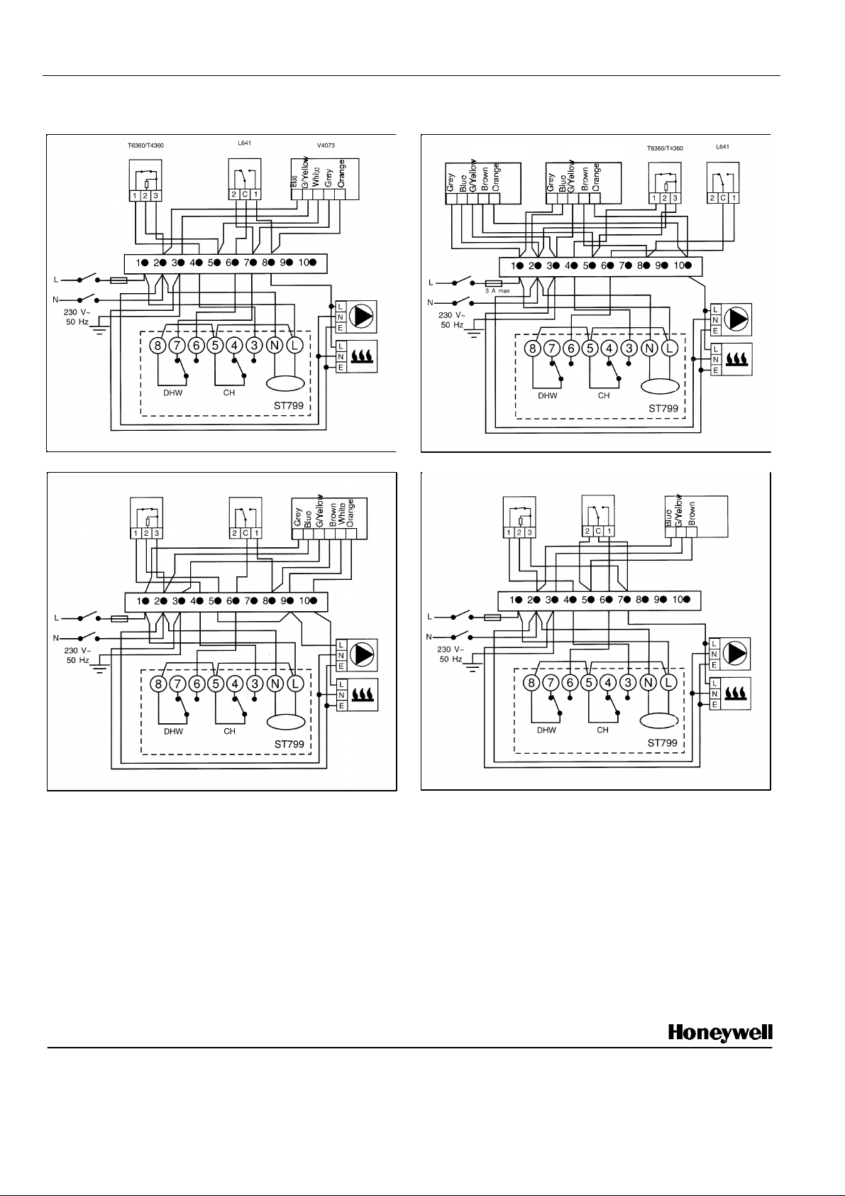
In the Sundial S, W, and Y Plan wiring diagrams,
S-Plan
Y-Plan
ROOM STAT.
CYLINDER
BOILER
PUMP
CLOCK
ROOM STAT.
CYLINDER
V4043H
HOT
BOILER
PUMP
CLOCK
V4043H
C-Plan
T6360/T4360
L641
V4043H
BOILER
PUMP
CLOCK
W-Plan
T6360/T4360
L641
V4044
BOILER
PUMP
CLOCK
SUNDIAL PLAN WIRING DIAGRAMS
3 A max
ROOM STAT.
STAT.
CYLINDER
STAT.
MID-POSITION VALVE
2 PORT ZONE VALVE
HEATING
2 PORT ZONE VALVE
ROOM STAT.
WATER
2 PORT ZONE VALVE
CYLINDER
STAT.
STAT.
DIVERTING VALVE
3 A max
connections are shown to basic boilers only. For
wiring connections to pump overrun boilers refer to
boiler manufacturers instructions or Honeywell for
assistance.
3 A max
Final Assembly
When the wiring is completed, replace the terminal cover
ensuring it is correctly installed with ends located under the
tabs and the locking pin through the locating hole.
Replace the timer onto the wallplate, ensuring it is firmly
secured by the three securing clips.
Switch on the power and refer to the user's guide for
programming details.
If the display remains blank, press the RESET button
with a blunt object. (e.g. a pencil)
Honeywell Control Systems Limited Helping You Control Your World
Newhouse Industrial Estate
Motherwell ML1 5SB
United Kingdom
EN0R 8440 R0
 Loading...