

Page 1
Installation Instructions for the
SS490 Series Miniature Ratiometric
Linear Hall-Effect Sensor ICs
SOLDERING INSTRUCTIONS
NOTICE
Do not wave solder surface mount sensor ICs (catalog listings
with suffixes -S or -SP). Wave soldering may negatively affect
sensor performance and reliability, and will void Honeywell’s
warranty.
Surface mount (catalog listings with suffixes -S or -SP): Use
infrared reflow process with active flux, lead-free solder. Do not
exceed peak temperature of 245 °C [473 °F] for a maximum of 10
seconds.
Through-hole leads: Wave solder at 250 °C to 260 °C [482 °F to
500 °F] for a maximum of 3 seconds. Burrs are allowed only if full
length of leads will pass through hole.
CLEANING INSTRUCTIONS
CAUTION
PRODUCT DAMAGE
Use agitated rinse, not pressure wash, in order to avoid forcing
contamninats into the sensor package.
Failure to comply with these instructions may result in
product damage.
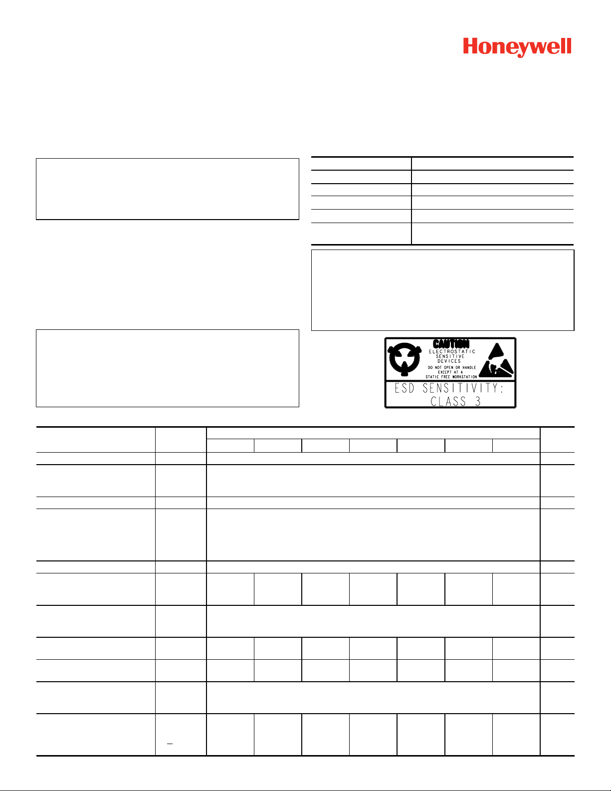
Table 1. Absolute Maximum Ratings
Characteristic
Supply voltage (Vs) -0.5 Vdc to 11 Vdc
Output current 10 mA
Operating temperature -40 °C to 150 °C [-40 °F to 302 °C]
Storage temperature -55 °C to 165 °C [-67 °F to 329 °C]
Magnetic flux
NOTICE
Absolute maximum ratings are the extreme limits that the device
will withstand without damage to the device. However, the
electrical and mechanical characteristics are not guaranteed as
the maximum limits (above recommended operating conditions)
are approached, nor will the device necessarily operate at
absolute maximum ratings.
PK 88840
Issue 6
Parameter
no limit - circuit cannot be damaged by
magnetic overdrive
Table 2. Specifications (Vs = 5.0 Vdc, Ta = -40 °C to 125 °C [-40 °F to 257 °F] unless otherwise noted.)
Characteristic Condition
Supply voltage — 4.5 to 10.5 Vdc
Supply current:
typical
maximum
Output type (sink or source) — ratiometric —
Output current:
typical (sink or source)
minimum (source)
minimum (sink)
minimum (sink)
Operating temperature — -40 to 150 [-40 to 302] °C [°F]
Magnetic range:
typical
minimum
Output voltage span:
typical
maximum
Null
Sensitivity —
Linearity:
typical
maximum
Temperature error:
Null drift
Sensitivity drift
at 25 °C 7.0
Vs > 4.5 V
Vs > 4.5 V
Vs > 4.5 V
Vs > 5.0 V
—
— 0.2 to (Vs-0.2)
output at 0
Gauss
— -1.0
—
>25 °C
<25 °C
SS494A SS495A1 SS495A2 SS495B SS496A SS496A1 SS496B
±670
±600
2.50
±0.075
3.125
±0.125
±0.06
-0.01, +0.05
-0.0, +0.06
±670
±600
2.50
±0.075
3.125
±0.094
±0.04
-0.02, +0.06
-0.0, +0.06
Catalog Listing Prefix
±670
±600
2.50
±0.100
3.125
±0.156
±0.07
-0.02, +0.06
-0.01, +0.07
±670
±600
0.4 to (Vs-0.4)
±0.150
3.125
±0.250
±0.08
-0.01, +0.05
-0.02, +0.06
8.7
1.5
1.0
0.6
1.0
2.50
-1.5
±840
±750
2.50
±0.075
2.50
±0.100
±0.048
-0.01, +0.05
-0.0, +0.06
±840
±750
2.50
±0.075
2.50
±0.075
±0.03
-0.01, +0.05
-0.0, +0.06
±840
±750
2.50
±0.150
2.50
±0.200
±0.06
-0.02, +0.06
-0.02, +0.06
Unit
mA
mA
Gauss
mV/G
% Span
%/°C
V
V
Page 2
SS490 Series Miniature Ratiometric
4.5
640
10.5
Ambient Temperature (°C)
Supply Voltage (V)
egion
Vs (+)
Output (0)
Vs (-)
4.5
800
ISSUE 6
Linear Hall-Effect Sensor ICs
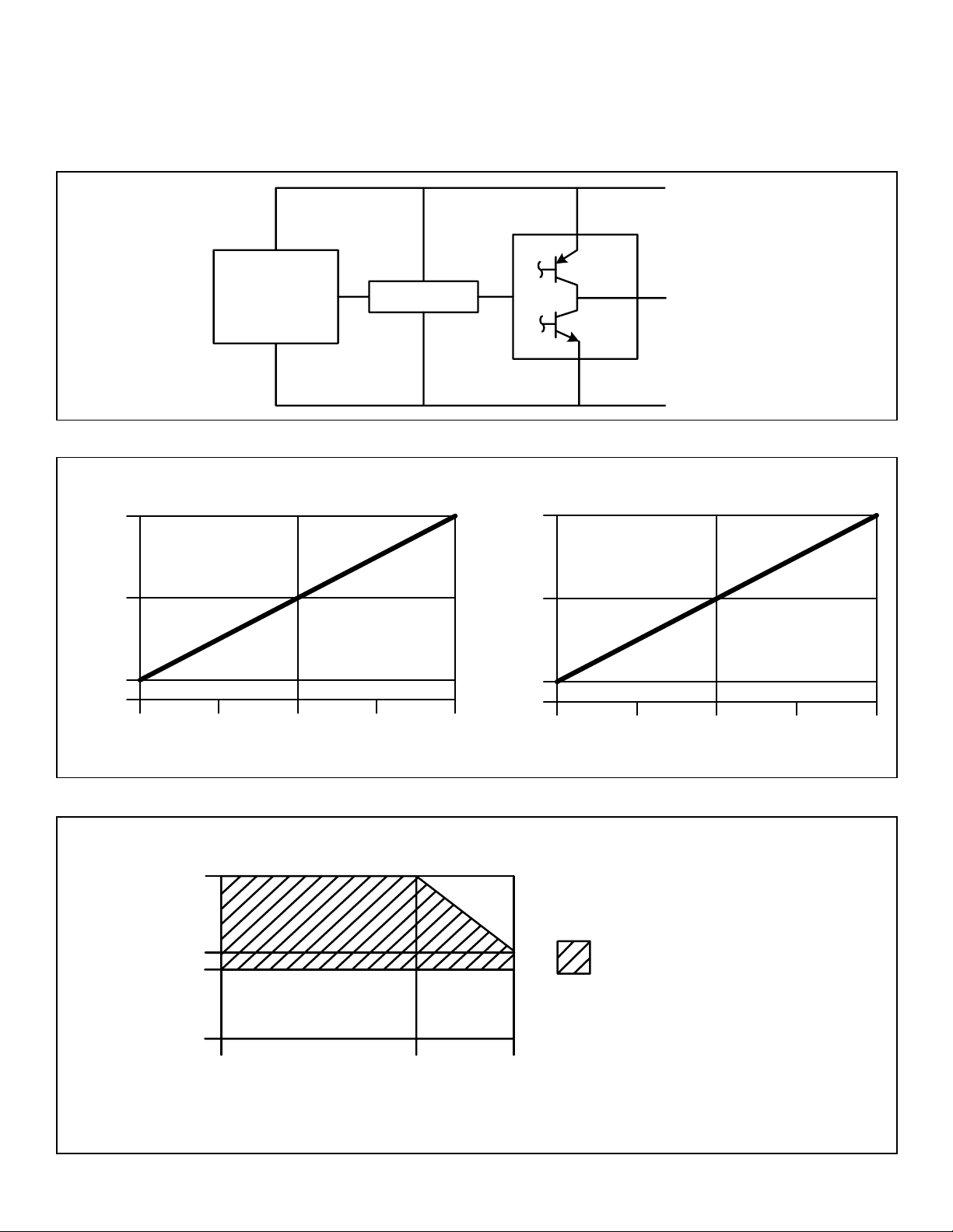
Figure 1. Block/Electrical Diagram
Hall Sensor
Figure 2. Typical Ouptut vs Gauss (Vs = 5.0 Vdc)
All Catalog Listings Beginning with SS495
Amplier
PK 88840
All Catalog Listings Beginning with SS496
2.5
Output Voltage (V)
0.5
0
0-640 -320 320
Gauss (G)
Figure 3. Maximum Allowable Ambient Temperature
5.5
4.5
0
2.5
Output Voltage (V)
0.5
0
0-800 -400 400
Gauss (G)
Acceptable operating r
2 Honeywell Sensing and Control
0
125
150
Page 3
SS490 Series Miniature Ratiometric
[0.880]
ADHESIVE TAPE
[0.880]
ADHESIVE TAPE
[0.050]
ISSUE 6
Linear Hall-Effect Sensor ICs
PK 88840
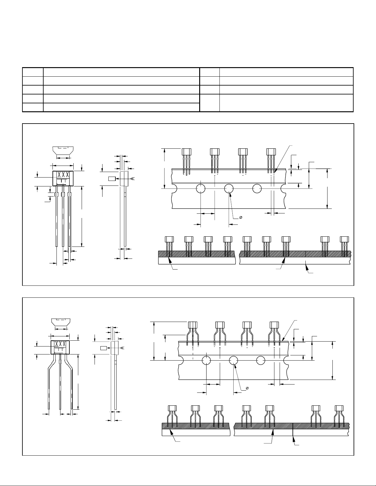
Table 3. Suffix Nomenclature for the SS4 Package:
Suffix Description Suffix Description
-Blank 14,99 mm [0.590 in] straight standard leads, bulk pack -S 3,30 [0.130 in] surface mount, bulk pack
-T3 14,99 mm [0.590 in] straight standard leads, ammo pack tape in box -SP 3,30 [0.130 in] surface mount, pocket tape and reel
-F 14,99 mm [0.590 in] formed leads, bulk pack -L 18,67 mm [0.735 in] straight long leads, bulk pack
-T2 14,99 mm [0.590 in] formed leads, ammo pack tape in box
Figure 4. Dimensional Drawings for Catalog Listings with Suffixes -Blank and -T3 (For Reference Only: mm/[in].)
-Blank (Straight Standard Leads)
2,54
4,06 ±0,051
[0.160 ±0.002]
1,75 ±0,051
[0.069 ±0.010]
3X 0,76
[0.030]
[0.100]
2,98 ±0,051
[0.118 ±0.002]
14,99
[0.590]
2,77
[0.109]
0,46
[0.018]
N S
0,89 MAX.
[0.035]
1,57 ±0,051
[0.062 ±0.002]
22,35
6,35 ±1,295
[0.250 ±0.051]
-T3 (Straight Standard Leads on Ammo Pack Tape)
0,51 MAX.
[0.157 ±0.012]
12,7 ±0,305
[0.500 ±0.012]
12,7 ±0,305
[0.020]
5,97
[0.235]
1,27 +0,381, -0,102
[0.050 +0.015, -0.004]
8,99 +0,762, -0,510
[0.354 +0.030, -0.020]
18,009 +0,991, -0,510
[0.709 +0.039, -0.020]
+-
2X 1,3
0
3X 0,64 MAX.
[0.025]
3X 0,38
[0.015]
3X 0,38
[0.015]
0,76 ±0,076
[0.030 ±0.003]
SENSOR 1
SENSOR 24
Figure 5. Dimensional Drawings for Catalog Listings with Suffixes -F and -T2 (For Reference Only: mm/[in].)
-T2 (Formed Leads on Ammo Pack Tape)
6,35 ±1,295
12,7 ±0,305
[0.500 ±0.012]
[0.157 ±0.012]
12,7 ±0,305
4,06 ±0,051
[0.160 ±0.002]
1,75 ±0,051
[0.069 ±0.010]
2X 2,54
[0.100]
-F (Formed Leads)
2,54
[0.100]
2,98 ±0,051
[0.118 ±0.002]
14,99
[0.590]
+-
0
[0.015]
3X 0,38
2,77
[0.109]
0,46
[0.018]
N S
0,89 MAX.
[0.035]
1,57 ±0,051
[0.062 ±0.002]
3X 0,38
[0.015]
0,76 ±0,076
[0.030 ±0.003]
22,35
16,00 ±1,295
[0.630 ±0.051]
[0.250 ±0.051]
FOLD
0,51 MAX.
[0.020]
5,97
[0.235]
2,54 +0,381, -0,102
[0.100 +0.015, -0.004]
8,99 +0,762, -0,510
[0.354 +0.030, -0.020]
18,009 +0,991, -0,510
[0.709 +0.039, -0.020]
SENSOR 1
SENSOR 24
FOLD
Honeywell Sensing and Control 3
Page 4
SS490 Series Miniature Ratiometric
3X 1,499 MIN.
2,54
[0.100]
4,06 ±0,051
[0.160 ±0.002]
3X 0,38
[0.015]
18,67
[0.735]
3X 0,38
[0.015]
2X 1,3
[0.050]
2X 1,3
[0.050]
1,57 ±0,051
[0.062 ±0.002]
2,98 ±0,051
[0.118 ±0.002]
+-
0
1,83 ±0,152
[0.072 ±0.006]
0,762 ±0,051
[0.030 ±0.002]
[0.050]
ISSUE 6
Linear Hall-Effect Sensor ICs
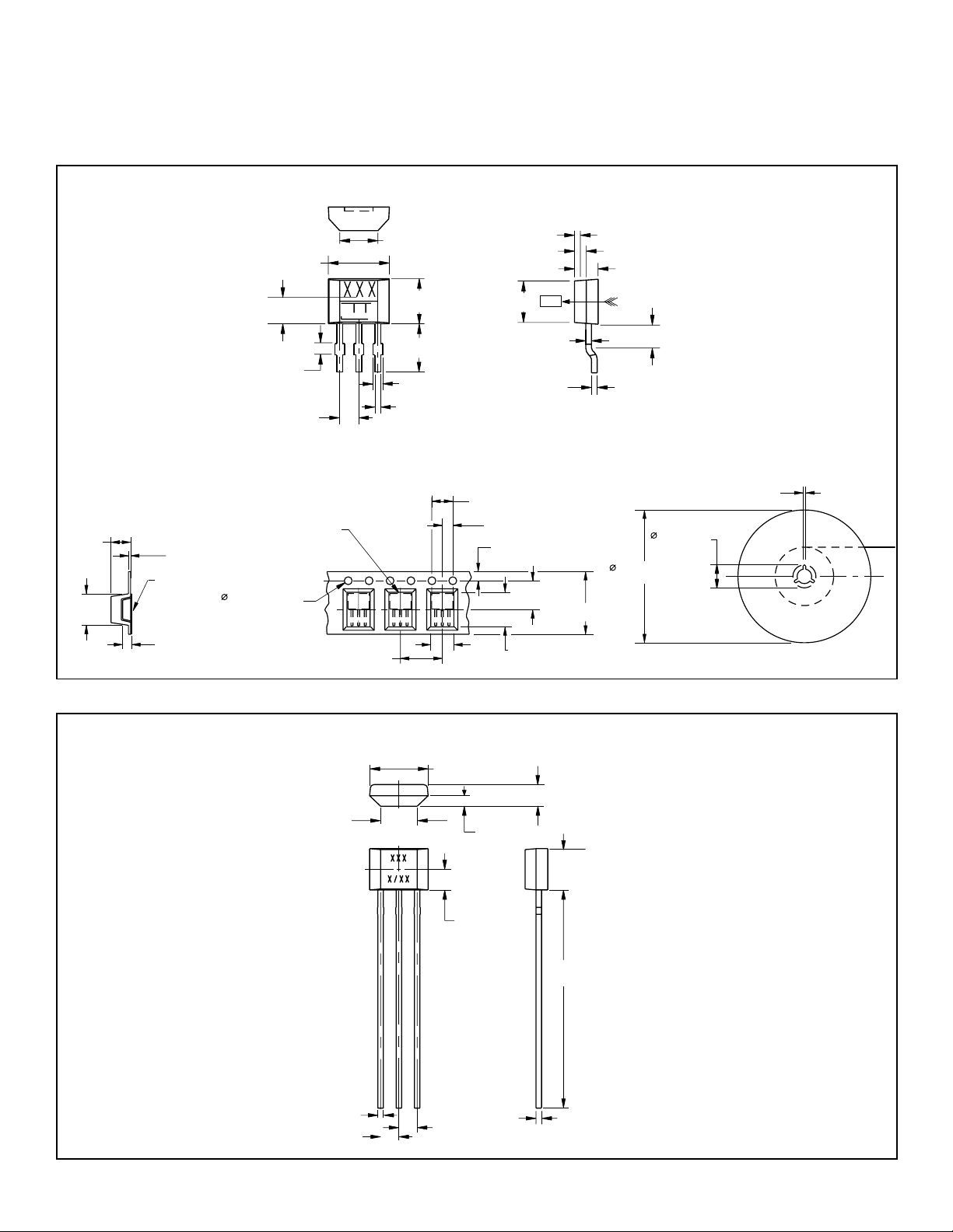
Figure 6. Dimensional Drawings for Catalog Listings with Suffixes -S and -SP (For Reference Only: mm/[in].)
-S (Surface Mount)
0,46
[0.018]
1,57 ±0,051
[0.062 ±0.002]
1,52 ±0,254
[0.060 ±0.010]
[1.300 ±0.031]
[7.01 ±0.08]
11,99 ±0,051
[0.472 ±0.002]
178.05 ±2,032
33,02 ± 0,787
DIRECTION OF FEED FROM REEL
2,41 MAX.
[0.095]
7, 11 MAX.
[0.280]
0,406 MAX.
[0.016]
TOP COVER TAPE
0,102 MAX.
[0.004]
[0.059 +0.004, -0.000]
1,70
[0.067]
14,99 ±0,102, -0.00
4,06 ±0,051
[0.160 ±0.002]
1,75 ±0,051
[0.069 ±0.010]
3X 0,76
[0.030]
2X 1,3
EMBOSSMENT
2,54
[0.100]
2,98 ±0,051
[0.118 ±0.002]
3,18 ±0.38
[0.015 +0.005, -0.002]
+-
[0.125 ±0.015]
0
3X 0,64 MAX.
[0.025]
3X 0,38
[0.015]
0,89 MAX.
[0.035]
2,77
N S
[0.109]
3X 0,38 ±0,127, -0.051
3X 0,38 ±0,051]
[0.015 ±0.002]
-SP (Surface Mount on Pocket Tape and Reel)
(not to scale)
3,99 ±0,102
[0.157 ±0.004]
2,01 ±0,051
[0.079 ±0.002]
1,75 ±0,102
[0.069 ±0.004]
5,51 ±0,051
[0.217 ±0.002]
4,42
6,60
8,00 ±0,102
[0.315 ±0.004]
[0.174]
[0.260]
PK 88840
[0.059]
Figure 7. Dimensional Drawings for Catalog Listings with Suffix -L (For Reference Only: mm/[in].)
-L (Straight Long Leads)
4 Honeywell Sensing and Control
Page 5

SS490 Series Miniature Ratiometric
ISSUE 6
Linear Hall-Effect Sensor ICs
WARNING
PERSONAL INJURY
DO NOT USE these products as safety or emergency stop
devices or in any other application where failure of the product
could result in personal injury.
Failure to comply with these instructions could result in
death or serious injury.
WARRANTY
Honeywell warrants goods of its manufacture as being free of
defective materials and faulty workmanship. Honeywell’s standard
product warranty applies unless agreed to otherwise by Honeywell
in writing; please refer to your order acknowledgement or consult
your local sales office for specific warranty details. If warranted
goods are returned to Honeywell during the period of coverage,
Honeywell will repair or replace, at its option, without charge those
items it finds defective. The foregoing is buyer’s sole remedy
and is in lieu of all warranties, expressed or implied, including
those of merchantability and fitness for a particular purpose.
In no event shall Honeywell be liable for consequential,
special, or indirect damages.
PK 88840
SALES AND SERVICE
Honeywell serves its customers through a worldwide network
of sales offices, representatives and distributors. For application
assistance, current specifications, pricing or name of the nearest
Authorized Distributor, contact your local sales office or:
E-mail: [email protected]
Internet: honeywell.com
Phone and Fax:
Asia Pacific +65 6355-2828
+65 6445-3033 Fax
Europe +44 (0) 1698 481481
+44 (0) 1698 481676 Fax
Latin America +1-305-805-8188
+1-305-883-8257 Fax
USA/Canada +1-800-537-6945
+1-815-235-6847
+1-815-235-6545 Fax
While we provide application assistance personally, through our
literature and the Honeywell web site, it is up to the customer to
determine the suitability of the product in the application.
Specifications may change without notice. The information we
supply is believed to be accurate and reliable as of this printing.
However, we assume no responsibility for its use.
Sensing and Control
Honeywell
1985 Douglas Drive North
Golden Valley, MN 55422
honeywell.com
PK 88840-6-EN
February 2014
© 2014 Honeywell International Inc. All rights reserved.
 Loading...