

Page 1

Honeywell Process Solutions
SmartLine Wireless Transmitter
User’s manual
34-SW-25-01
Revision 2
October 2018
Page 2

Page 3

iii SmartLine Wireless User's Manual Revision 2
Notices and Trademarks
Copyright 2018 by Honeywell International Inc.
Revisions 2, October 2018
While this information is presented in good faith and believed to be accurate, Honeywell disclaims the implied
warranties of merchantability and fitness for a particular purpose and makes no express warranties except as may
be stated in its written agreement with and for its customers.
In no event is Honeywell liable to anyone for any indirect, special or consequential damages. The information and
specifications in this document are subject to change without notice.
Honeywell, PlantScape, Experion PKS, and TotalPlant are registered trademarks of Honeywell International Inc.
Other brand or product names are trademarks of their respective owners.
Honeywell Process Solutions
1250 W Sam Houston Pkwy S
Houston, TX 77042
Page 4

iv SmartLine Wireless User's Manual Revision 2
About This Document
This document describes preparation, operation and maintenance of the SmartLineTM Wireless Pressure
Transmitters. Mounting, installation and wiring are covered in other documents.
Honeywell does not recommend using devices for critical control where there is a single point of failure
or where single points of failure result in unsafe conditions. OneWireless is targeted at open loop
control, supervisory control, and controls that do not have environmental or safety consequences. As
with any process control solution, the end-user must weigh the risks and benefits to determine if the
products used are the right match for the application based on security, safety, and performance.
Additionally, it is up to the end-user to ensure that the control strategy sheds to a safe operating condition
if any crucial segment of the control solution fails.
Revision Information
Document Name
SmartLine Wireless User's Manual
Document ID
(This document)
Revision
Number
Publication Date
1st Release
34-SW-25-01
1
September 2018
RoHS added
34-SW-25-01
2
October 2018
References
The following list identifies all documents that may be sources of reference for material discussed in this
publication.
Document Title
Doc #
STDW800 Wireless Specification, Differential Transmitter
34-SW-03-01
STAW800 Wireless Specification, Absolute Transmitter
34-SW-03-02
STGW800 Wireless Specification, Gauge Transmitter
34-SW-03-03
STFW700_800 Wireless Specification, Flanged Transmitter
34-SW-03-04
STRW700_800 Wireless Specification, Remote Seal Transmitter
34-SW-03-05
STDW700 Wireless Specification, Differential Transmitter
34-SW-03-06
STAW700 Wireless Specification, Absolute Transmitter
34-SW-03-07
STGW700 Wireless Specification, Gauge Transmitter
34-SW-03-08
OneWireless R310 Release Notes
OWDOC-X252-en-310A
OneWireless R310 Migration Users Guide
OWDOC-X258-en-310
OneWireless R310 Field Device Access Point Users Guide
OWDOC-X256-en-310
OneWireless R310 Wireless Device Manager Users Guide
OWDOC-X254-en-310
OneWireless R300 Experion PKS Integration Guide
OWDOC-X259-en-300
OneWireless R300 Wireless LAN Controller Configuration Guide
OWDOC-X255-en-300
OneWireless R300 Network Planning an Installation Guide
OWDOC-X253-en-300
Page 5

Revision 2 SmartLine Wireles User's Manual v
Support and Contact Information
For Europe, Asia Pacific, North and South America contact details, refer to the back page of this
manual or the appropriate Honeywell Support web site:
Honeywell Corporate www.honeywell.com
Honeywell Process Solutions https://www.honeywellprocess.com/*
Training Classes https://www.honeywellprocess.com/en-US/training
Telephone and Email Contacts
Area
Organization
Phone Number
United States and
Canada
Honeywell Inc.
1-800-343-0228 Customer Service
1-800-423-9883 Global Technical Support
Global Email
Support
Honeywell Process Solutions
Page 6
vi SmartLine Wireless User's Manual Revision 2
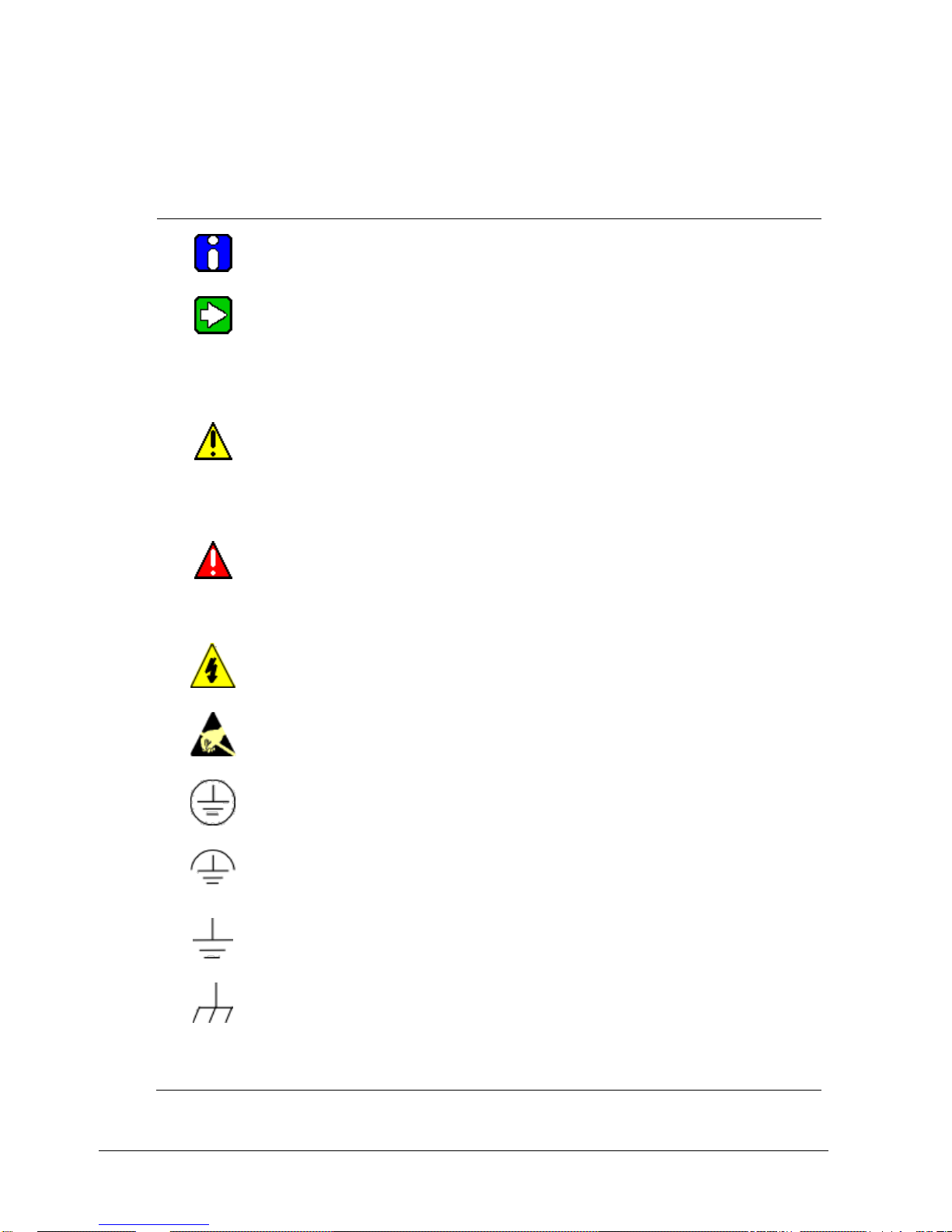
Symbol Definitions
The following table lists those symbols used in this document to denote certain conditions.
Symbol
Definition
ATTENTION: Identifies information that requires special consideration.
TIP: Identifies advice or hints for the user, often in terms of performing a task.
CAUTION
Indicates a situation which, if not avoided, may result in equipment or work (data) on
the system being damaged or lost, or may result in the inability to properly operate
the process.
CAUTION: Indicates a potentially hazardous situation which, if not avoided, may
result in minor or moderate injury. It may also be used to alert against unsafe
practices.
CAUTION symbol on the equipment refers the user to the product manual for
additional information. The symbol appears next to required information in the
manual.
WARNING: Indicates a potentially hazardous situation, which, if not avoided, could
result in serious injury or death.
WARNING symbol on the equipment refers the user to the product manual for
additional information. The symbol appears next to required information in the
manual.
WARNING, Risk of electrical shock: Potential shock hazard where HAZARDOUS
LIVE voltages greater than 30 Vrms, 42.4 Vpeak, or 60 VDC may be accessible.
ESD HAZARD: Danger of an electro-static discharge to which equipment may be
sensitive. Observe precautions for handling electrostatic sensitive devices.
Protective Earth (PE) terminal: Provided for connection of the protective earth
(green or green/yellow) supply system conductor.
Functional earth terminal: Used for non-safety purposes such as noise immunity
improvement. NOTE: This connection shall be bonded to Protective Earth at the
source of supply in accordance with national local electrical code requirements.
Earth Ground: Functional earth connection. NOTE: This connection shall be
bonded to Protective Earth at the source of supply in accordance with national and
local electrical code requirements.
Chassis Ground: Identifies a connection to the chassis or frame of the equipment
shall be bonded to Protective Earth at the source of supply in accordance with
national and local electrical code requirements.
continued
Page 7

Revision 2 SmartLine Wireles User's Manual vii
Symbol
Description
The Factory Mutual® Approval mark means the equipment has
been rigorously tested and certified to FM standards for safety
and/or performance.
The Canadian Standards mark means the equipment has been
tested and meets applicable standards for safety and/or
performance.
The Ex mark means the equipment complies with the requirements
of the European standards that are harmonized with the 94/9/EC
Directive (ATEX Directive, named after the French "ATmosphere
EXplosible").
For radio equipment used in the European Union in accordance
with the Radio Equipment Directive (RED) and the CE Mark. The
alert sign must be used when a restriction on use (output power
limit by a country at certain frequencies) applies to the equipment
and must follow the CE marking.
The C-Tick mark is a certification trade mark registered to ACMA
(Australian Communications and Media Authority) in Australia under
the Trade Marks Act 1995 and to RSM in New Zealand under
section 47 of the NZ Trade Marks Act. The mark is only to be used
in accordance with conditions laid down by ACMA and RSM. This
mark is equal to the CE Mark used in the European Union.
N314 directly under the logo is Honeywell’s unique supplier
identification number.
The ISA100 Wireless Compliant logo indicates the device has
received ISA100.11a conformance certification and is registered
with the Wireless Compliance Institute, assuring device
interoperability.
CRN
Canadian Registration Number
Page 8

Page 9

ix SmartLine Wireless User's Manual Revision 2
Contents
Honeywell Process Solutions ................................................................................................................ iii
Symbol Definitions ..................................................................................................................................vi
1. INTRODUCTION .................................................................................................... 1
1.1 Purpose .......................................................................................................................................... 1
1.2 Scope .............................................................................................................................................. 1
1.3 OneWireless network overview ................................................................................................... 1
1.4 Security Considerations ............................................................................................................... 1
1.5 Licensing and License Keys for Anti-Aliasing Filter ................................................................. 1
1.6 About the transmitter .................................................................................................................... 2
1.7 Physical Characteristics ............................................................................................................... 4
2. PREPARATION AND QUICK START ................................................................... 6
2.1 Introduction ................................................................................................................................... 6
2.2 Set up the Network ........................................................................................................................ 6
2.3 Transmitter Quick Start ................................................................................................................ 6
3. INSTALLATION ..................................................................................................... 8
3.1 Installation Site Evaluation .......................................................................................................... 8
3.2 Maximum Working Pressure: ....................................................................................................... 8
3.3 Environmental Conditions: .......................................................................................................... 8
3.4 Transmitter Weights and Dimensions ......................................................................................... 9
Weights ..................................................................................................................................................................9
Dimensions ........................................................................................................................................................... 10
3.5 Installation drawing number tables ...........................................................................................14
3.6 Conduit / Cable Entries ...............................................................................................................15
Summary .............................................................................................................................................................. 15
3.7 Mounting Summary .....................................................................................................................16
3.8 Piping the SmartLine Wireless Transmitter .............................................................................23
3.9 Rotate transmitter housing ........................................................................................................27
3.10 Rotate display ..........................................................................................................................27
Tools required ...................................................................................................................................................... 27
Procedure ............................................................................................................................................................. 27
Display adjustment ............................................................................................................................................... 28
3.11 Antenna adjustment and mounting .......................................................................................29
Requirements ....................................................................................................................................................... 29
Integral antenna ................................................................................................................................................... 29
Page 10

Contents
Telephone and Email Contacts
x SmartLine Wireless User's Manual Revision 2
3.12 Remote antenna .......................................................................................................................31
Outdoor installation warnings ............................................................................................................................... 31
Choosing a Mounting Location ............................................................................................................................. 32
Site Selection ....................................................................................................................................................... 32
Mounting the Antenna .......................................................................................................................................... 33
Directional mounting procedure ........................................................................................................................... 34
Omnidirectional mounting procedure ................................................................................................................... 35
Grounding the antenna ........................................................................................................................................ 36
4. START UP ........................................................................................................... 38
4.1 Battery Power Option..................................................................................................................38
Install/Replace batteries ....................................................................................................................................... 38
Battery Pack installation and replacement procedure .......................................................................................... 40
Battery Pack Test Terminals ................................................................................................................................ 40
4.2 24V Power Supply Option ..........................................................................................................41
24V Power Supply ............................................................................................................................................... 42
24V Power Supply Connection/Replacement Procedure ..................................................................................... 43
4.3 Grounding ....................................................................................................................................44
24V dc Power Supply Option (DC) System Diagram ........................................................................................... 44
4.4 Display sequence ........................................................................................................................45
4.5 Provisioning .................................................................................................................................45
4.6 Calibrating the transmitter .........................................................................................................46
Overview .............................................................................................................................................................. 46
Calibrate zero ....................................................................................................................................................... 46
Procedure for field calibration of Honeywell compound characterized SmartLine Wireless Transmitters ............ 47
5. FUNCTION BLOCKS ........................................................................................... 50
5.1 Introduction .................................................................................................................................50
5.2 Block description ........................................................................................................................50
Block types ........................................................................................................................................................... 50
Block diagram ...................................................................................................................................................... 50
6. OPERATION ........................................................................................................ 51
6.1 Overview ......................................................................................................................................51
Display modes ..................................................................................................................................................... 51
6.2 Transmitter connection status ...................................................................................................52
6.3 Transmitter PV display ...............................................................................................................54
PV status ................................................................ ................................ .............................................................. 57
6.4 Provisioning Device menus .......................................................................................................60
Overview .............................................................................................................................................................. 60
Main menu ........................................................................................................................................................... 60
Security and Node Deployment ........................................................................................................................... 60
De-provisioning .................................................................................................................................................... 62
Read Device Information ................................................................................................................................ ...... 62
Advanced Options ................................................................................................................................................ 64
Page 11

Contents
Telephone and Email Contacts
Revision 2 SmartLine Wireles User's Manual xi
7. MAINTENANCE/REPAIR..................................................................................... 66
7.1 Introduction .................................................................................................................................66
7.2 Preventive maintenance .............................................................................................................66
7.3 Inspecting and cleaning barrier diaphragms ...........................................................................66
Tools required ...................................................................................................................................................... 66
Procedure ............................................................................................................................................................. 67
Torque ratings ...................................................................................................................................................... 69
7.4 Replacing Electronics Module ...................................................................................................70
Tools required ...................................................................................................................................................... 70
Procedure ............................................................................................................................................................. 70
7.5 Replacing batteries .....................................................................................................................71
When to replace ................................................................................................................................................... 71
7.6 Replacing 24V external power module .....................................................................................71
When to replace ................................................................................................................................................... 71
7.7 Replacing antenna ......................................................................................................................72
Tools required ...................................................................................................................................................... 72
Procedure ............................................................................................................................................................. 72
Antenna replacement procedure .......................................................................................................................... 73
8. PARTS ................................................................................................................. 75
7.8 Transmitter body .........................................................................................................................75
Mounting Brackets ................................................................................................................................................ 76
APPENDIX A - MODBUS ............................................................................................. 87
APPENDIX B - CERTIFICATIONS AND APPROVALS ............................................... 94
Hazardous location certifications .......................................................................................................................... 98
Battery ................................................................................................................................................................ 101
24V DC Supply ................................................................................................................................................... 101
B3. Conditions of Certification ..........................................................................................................102
FM Approval Specific Conditions of Use ............................................................................................................ 102
CSA, IECEx and ATEX Conditions of Certification ............................................................................................. 102
Apparatus Marked with Multiple Types of Protection .......................................................................................... 102
B4. Radio Compliance Information ...................................................................................................103
Radio Frequency (RF) statement ....................................................................................................................... 103
European Union restriction ................................................................................................................................. 103
Restriction .......................................................................................................................................................... 103
Japanese Restrictions ........................................................................................................................................ 104
FCC compliance statements .............................................................................................................................. 104
IC compliance statements .................................................................................................................................. 104
Page 12

Contents
Tables
xii SmartLine Wireless User's Manual Revision 2
Tables
Table 3-1: Weights ..................................................................................................................... 9
Table 3-2: Drawing numbers for pressure transmitters ............................................................. 14
Table 3-3: Conduit entry plugs and cable glands for your transmitter. ...................................... 15
Table 3-4: Flange Mounting Guidelines .................................................................................... 22
Table 3-5: Remote Diaphragm Mounting Details ...................................................................... 23
Table 3-6: Suggested Connection Locations ............................................................................ 25
Table 4-1: Calibrate zero .......................................................................................................... 46
Table 4-2: Field calibration ....................................................................................................... 47
Table 5-1: Blocks...................................................................................................................... 50
Table 6-1: Transmitter connection status .................................................................................. 52
Table 6-2: Transmitter PV display ............................................................................................ 54
Table 6-3: SmartLine Wireless DP units ................................................................................... 54
Table 6-4: SmartLine Wireless Flow units ................................................................................ 56
Table 6-5: PV Status ................................................................................................................ 57
Table 6-6: Device status ........................................................................................................... 58
Table 6-7: Read Device Information ......................................................................................... 63
Table 6-8: Advanced Options ................................................................................................... 65
Table 7-1: Inspecting and Cleaning Barrier Diaphragms .......................................................... 67
Table 7-2: Head Bolt Torque Values ........................................................................................ 69
Table 7-3: Electronics module replacement .............................................................................. 70
Table 8-1: Transmitter Body Parts ............................................................................................ 75
Table 8-2: Angle and Flat Bracket Parts (Refer to Figure 8-1) .................................................. 77
Table 8-3: Transmitter Enclosure O-Ring Kit ............................................................................ 77
Table 8-4: Meter Body Parts ..................................................................................................... 77
Table 8-5: Models STDW810, 820, 825, 830 & 870 .................................................................. 78
Table 8-6: Parts for STGW830, 840, 870 and STAW822, 840 Transmitter Body ...................... 81
Table 8-7: Inline Gauge and Inline Atmospheric Meter Body Parts ........................................... 84
Table 8-8: Flange-Mounted Meter Body Parts .......................................................................... 84
Table 8-9: SmartLine Wireless Pressure – Modbus table ......................................................... 87
Table 8-10 SmartLine Wireless – Modbus table ....................................................................... 90
Page 13

Contents
Figures
Revision 2 SmartLine Wireles User's Manual xiii
Figures
Figure 1-1 - SmartLine Wireless Transmitter Functional Diagram ............................................... 3
Figure 1-2 – SmartLine Wireless Transmitter Major Assemblies ................................................. 4
Figure 1-3– SmartLine Wireless Transmitter Electronics Housing Components .......................... 5
Figure 3-1: DP/DHGP Pressure transmitter dimensions unit mm/inch ................................ ....... 10
Figure 3-2: DP/DHGP Pressure antenna dimensions unit mm/inch ........................................... 11
Figure 3-3: GP/AP Pressure transmitter dimensions unit mm/inch ............................................ 12
Figure 3-4: GP/AP Pressure antenna dimensions unit mm/inch ................................................ 13
Figure 3-5: Typical Bracket Mounted and Flange Mounted Installations .................................... 16
Figure 3-6: Angle Mounting Bracket Secured to a Horizontal or Vertical Pipe ........................... 17
Figure 3-7: – Inline Model Mounted to an Optional Bracket ....................................................... 18
Figure 3-8: Rotating the Electronic Housing .............................................................................. 18
Figure 3-9: Using a Spirit Balance to Level a Transmitter .......................................................... 20
Figure 3-10: Tank-Flange Mounted Transmitter ........................................................................ 21
Figure 3-11: Representative Remote Diaphragm Seal Transmitter Installation.......................... 22
Figure 3-12: Typical 3-Valve Manifold with Blow-Down Piping .................................................. 24
Figure 3-13: Flange Adapter Removal and Replacement .......................................................... 26
Figure 3-14: Rotating transmitter housing ................................................................................. 27
Figure 3-15: Display rotation ..................................................................................................... 28
Figure 3-16: Elbow antenna adjustment .................................................................................... 30
Figure 3-17: Directional antenna mounting ................................................................................ 35
Figure 3-18: Omnidirectional antenna mounting ........................................................................ 36
Figure 4-1: IS Battery Pack Installation ..................................................................................... 39
Figure 4-2: IS Battery Pack ................................................................................................ ....... 39
Figure 4-3: 24V Power Supply Installation ................................................................................. 41
Figure 4-4: 24V Power Supply Module ...................................................................................... 42
Figure 4-5: Power Supply 24V dc Option (DC) System Diagram ............................................... 44
Figure 5-1: Block Diagram......................................................................................................... 50
Figure 6-1: Main menu .............................................................................................................. 60
Figure 6-2: Security and Node Deployment ............................................................................... 61
Figure 6-3: Read Device Information ......................................................................................... 62
Figure 6-4: Advanced Options ................................................................................................... 64
Figure 7-1: Assembly of DP Transmitter Process Heads ........................................................... 68
Figure 7-2: STW Standard Transmitter - Head Bolt Tightening Sequence ................................. 68
Figure 7-3: Sensor module removal and replacement ............................................................... 71
Figure 7-4: Antenna replacement .............................................................................................. 74
Figure 8-1: Angle and Flat Bracket Parts ................................................................................... 76
Figure 8-2: Models STDW810, 820, 825, 830, & 870 ................................................................ 80
Figure 8-3: STGW830, 840, 870, and STAW822, 840 Transmitter Body .................................. 83
Figure 8-4: Inline Gauge and Inline Atmospheric Display Bodies .............................................. 84
Figure 8-5: Extended Flange Design ......................................................................................... 85
Figure 8-6: Pseudo Flange design ............................................................................................ 85
Figure 8-7: Flush Flange Design ............................................................................................... 86
Figure 8-8: Remote Seal Diaphragm ......................................................................................... 86
Page 14

xiv SmartLine Wireless User's Manual Revision 2
Page 15

1. Introduction
1.1. Purpose
Revision 2 SmartLine Wireles User's Manual 1
1. Introduction
1.1 Purpose
This manual describes the Honeywell SmartLine Wireless Transmitter function, operation and
maintenance.
1.2 Scope
The manual includes:
Details of topics that relate uniquely to the Honeywell SmartLine Wireless Transmitter
1.3 OneWireless network overview
OneWireless is an all digital, two-way communication mesh network that interconnects industrial
field sensors to a central system.
OneWireless has defined standards to which field devices and operator stations communicate
with one another. The communications protocol is built as an "open system" to allow all field
devices and equipment that are built to OneWireless standard to be integrated into a system,
regardless of the device manufacturer. This interoperability of devices using OneWireless
technology is to become an industry standard for automation systems.
1.4 Security Considerations
Honeywell OneWireless Transmitters conform to the security features provided by compliance to
the ISA100.11a standard for both stack and device interoperability and security. The security
aspects of the ISA100.11a standard include multi-level authentication for endpoint validation,
data privacy consisting of network and end to end encryption, network diversity using spread
spectrum technology and time slot allocation, and data integrity using quality and latency
attributes.
For assure availability, the placement of Wireless transmitters and other wireless network
components should consider signal quality under various environmental conditions. Signal
quality can be monitored by inspection of the Receive Signal Strength Indicator (RSSI) and
Receive Signal Quality Indications (RSQI). The RSSI and RQSI for mesh links can be viewed on
the OneWireless Wireless Device Manager (WDM) network display.
Physical security of the transmitter relies on restricting access to the transmitter and related
network components to only authorized personal.
1.5 Licensing and License Keys for Anti-Aliasing Filter
This option enables the Anti-Alias filter which attenuates the higher frequencies and helps to
prevent aliasing components from being sampled.
License Keys can be purchased from Honeywell to Activate the Anti-Aliasing Filter Feature.
To Order Contact Honeywell and Provide the Device ID value for the transmitter you want to
buy the feature for. The Device ID can be found under “Device Vendor Parameters” in the WDM
interface.
Page 16

1. Introduction
1.6. About the transmitter
2 SmartLine Wireless User's Manual Revision 2
1.6 About the transmitter
The SmartLine Wireless Transmitter is furnished with an ISA100.11a-compliant wireless
interface to operate in a compatible distributed ISA100.11a wireless system. The transmitter will
interoperate with any ISA100.11a wireless network.
The transmitter includes ISA100.11a-compliant electronics for operating in a 2.4 GHz wireless
network. It features function block architecture and instantiable input channels.
The SmartLine Wireless Transmitter comes in a variety of models for measurement applications
involving one of these basic types of pressure:
Differential pressure
Gauge pressure
Absolute pressure
The transmitter measures the process pressure and transmits the measured value as a digital
output signal in user-configured engineering units. Its major components are an electronics
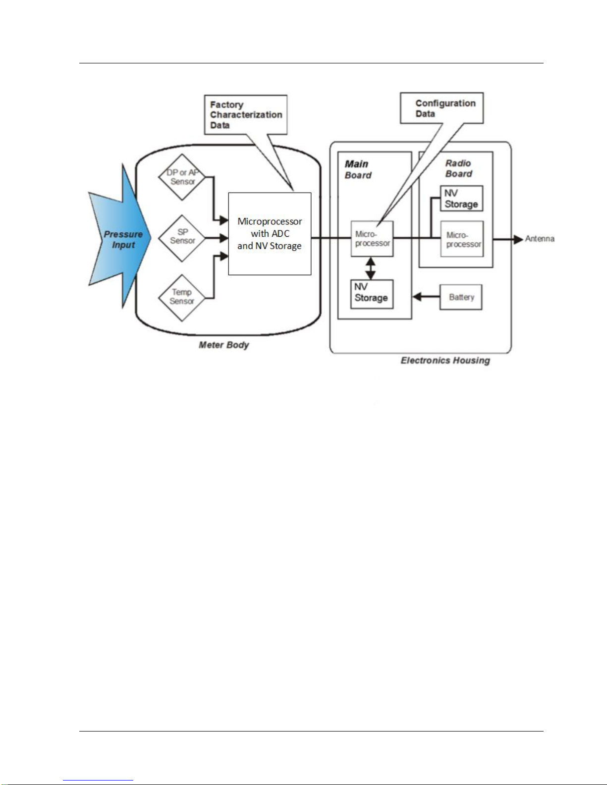
housing and a meter body as shown in Figure 1-1 (a typical differential pressure model
transmitter).
The SmartLine Wireless transmits its output in a digital OneWireless protocol format for direct
digital communications with systems.
The Process Variable (PV) is available for monitoring and alarm purposes. Available PV update
rates: 0.5, 1, 5, 10, 30 seconds, 1, 5, 15, 30 minutes and 1 hour are set on the OneWireless User
Interface. Slower update rates extend battery life. The meter body temperature is also available as
a secondary variable for monitoring. Figure 1-1 shows a block diagram of the SmartLine
Wireless Transmitter’s operating functions.
The SmartLine Wireless DP model type is capable of measuring mass flow and volumetric flow.
When minimum and maximum flow rate values are configured as PV scale 0% and 100% values
at given PV units of measure, and the respective DP values at those limits are configured as the
calibration scale 0% and 100% values, the PV value becomes a flow rate in the selected units of
measure. Minimum and maximum flow rate data at given DP values is either provided on or
with orifice plates, or is commonly available according to orifice plate size.
Page 17
1. Introduction
1.6. About the transmitter
Revision 2 SmartLine Wireles User's Manual 3
Figure 1-1 - SmartLine Wireless Transmitter Functional Diagram
Page 18
1. Introduction
1.7. Physical Characteristics
4 SmartLine Wireless User's Manual Revision 2
1.7 Physical Characteristics
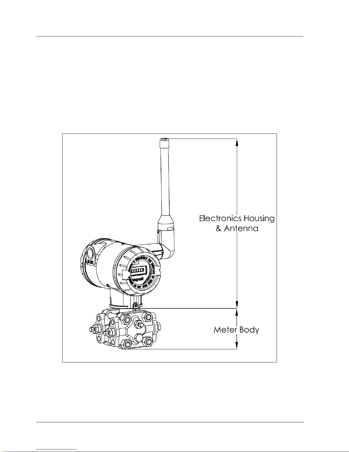
As shown in Figure 1-2, the SmartLine Wireless transmitter is packaged in two major assemblies: the
Electronics Housing and the meter body. The elements in the Electronic Housing respond to IR
commands and execute the software and protocol for the different pressure measurement types.
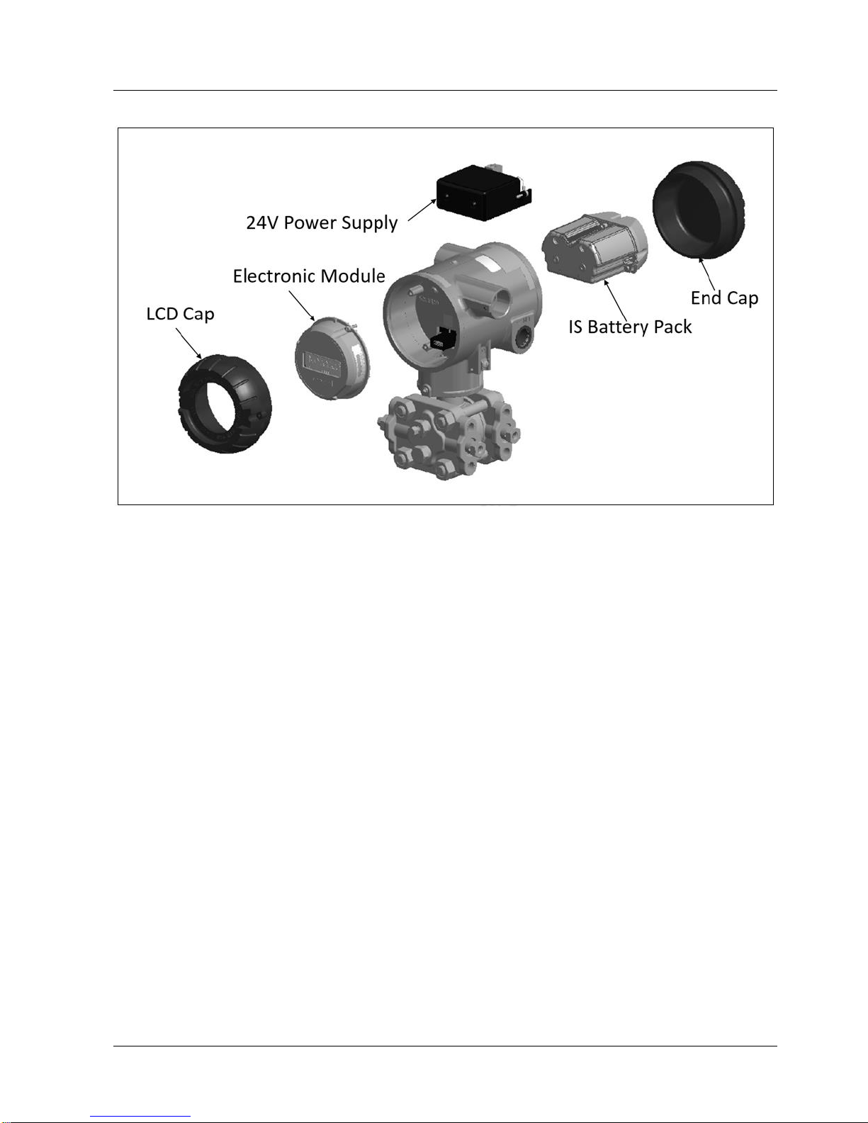
Figure 1-3 shows the assemblies in the Electronics Housing.
The meter body provides connection to a process system. Several physical interface configurations are
available, as determined by the mounting and mechanical connections, all of which are described in the
Installation section of this manual.
Figure 1-2 – SmartLine Wireless Transmitter Major Assemblies
Page 19
1. Introduction
1.7. Physical Characteristics
Revision 2 SmartLine Wireles User's Manual 5
Figure 1-3– SmartLine Wireless Transmitter Electronics Housing Components
Page 20

2. Preparation and Quick Start
2.1. Introduction
6 SmartLine Wireless User's Manual Revision 2
2. Preparation and Quick Start
2.1 Introduction
This section is useful if you are unfamiliar with the SmartLine Wireless transmitter, want a quick
start list, or if you want to configure and test your transmitter in an office environment before
installing it in its final location.
2.2 Set up the Network
Refer to the One Wireless Device Manager User Guide and Field Device Access Point User
Guide to setup the gateway, wireless device manager (WDM) and the access points (FDAP).
See References.
Ensure you have access to the WDM through the browser interface.
2.3 Transmitter Quick Start
1. INSTALL. If desired, mount or install the transmitter. If setting up in an office environment
for test, place the transmitter securely on a work surface.
2. ANTENNA. The transmitter can be supplied with an integral 4dBi antenna. If the transmitter
is equipped with a remote mount antenna connection, connect the antenna with a RF cable.
The transmitter remote mount and antennas utilize N-type connectors.
3. POWER up the transmitter.
Remove the end cap, opposite the LCD display, to connect power. Ensure the internal power
cable is connected to the battery pack or 24V supply module as applicable.
a. Battery Operated transmitters require two 3.6 V D-Size lithium thionyl chloride
batteries. See section 4.1 for specific battery requirements.
b. Line powered transmitters with the power supply option require 24V DC connected
to the input connector P3. See section 4.2 for details.
Once powered, verify that the transmitter LCD is functioning. If the LCD is blank, check the
power connections, and batteries as applicable.
4. PROVISION the transmitter to the network
a. Over The Air (OTA) provisioning can be done using the WDM interface.
i. Enable OTA provisioning on the access point closest to the transmitter.
On the WDM interface, select the access point, then on the property panel
expand and “Device Management” and under Over the Air Provisioning
press “Enable for 60 Minutes”
ii. Select the transmitter in the selection panel
iii. Press the provisioning green “Accept” check mark button
b. Handheld provisioning can be done through the IR port with a Handheld Provisioning
Device such as MCT404
Page 21

2. Preparation and Quick Start
2.3. Transmitter Quick Start
Revision 2 SmartLine Wireles User's Manual 7
See section 4.5 for further provisioning details. This step may take several minutes,
depending on your network.
5. VERIFY that the transmitter appears in the wireless network, and is transmitting PVs. This
step may take several minutes, depending on your network.
a. Drag the transmitter icon from the selection panel to the map (optional)
b. Load the DD file (if not done previously)
i. Select the transmitter.
ii. Press the maintenance “Templates” button.
iii. Press “Load DD File”, and select the DD .zip file.
iv. Refresh the browser to re-load the WDM web interface. This will require to
log in again.
c. Activate the channel
i. Select the transmitter channel to activate
ii. Press the Channel green “Activate” button
d. Configure the transmitter as desired using the property panel
i. Tag Name, Description, Display Tag, Routing assignment, Publication
frequency, Publication attributes, etc.
ii. Ensure the press “Apply” after the changes, and wait for the changes to take
effect.
e. Configure the channel as desired using the property panel.
i. Name, Description, Process limits, Process Scale, etc.
ii. Ensure to press “Apply” after the changes, and wait for the changes to take
effect.
6. INSTALL. If not done already, once the transmitter is verified to be functioning as expected,
it can be powered off and installed in the field. The provisioning key will remain.
7. CALIBRATE. If required, calibration should only be done after the transmitter is installed in
its final location. See section 4.6.
Page 22

3. Installation
3.1. Installation Site Evaluation
8 SmartLine Wireless User's Manual Revision 2
3. Installation
3.1 Installation Site Evaluation
Evaluate the site selected for the SmartLine Wireless Transmitter installation with respect to the
process system design specifications and Honeywell’s published performance characteristics for
your particular model. Some parameters that you may want to include in your site evaluation are:
Environmental Conditions:
o Ambient Temperature
o Relative Humidity
Potential Noise Sources:
o Radio Frequency Interference (RFI)
o Electromagnetic Interference (EMI)
Vibration Sources
o Pumps
o Motorized System Devices (e.g., pumps)
o Valve Cavitation
Process Parameters
o Temperature
o Maximum Pressure Rating
3.2 Maximum Working Pressure:
Refer to the applicable specification sheets in References
3.3 Environmental Conditions:
Refer to the specification sheet for performance considerations, see References
The transmitter operates with an ambient temperature of -40 oC to +85 oC. If installed in a
hazardous environment, the maximum ambient temperature may be limited. Refer to the control
drawing and the markings on the transmitter nameplate.
The process fluid temperature at the meter body operates from -40 oC to +125 oC.
Ambient humidity limits are 0 to 100% relative humidity.
The transmitter may be installed indoors or outdoors, with pollution degree 4. The enclosure is
rated Type 4X, IP66 / IP67.
The transmitter operates up to an altitude of 2,000 m.
Entry plugs/glands rated for the installation environment are required to be installed on the
transmitter.
Page 23

3. Installation
3.4. Transmitter Weights and Dimensions
Revision 2 SmartLine Wireles User's Manual 9
3.4 Transmitter Weights and Dimensions
Weights
Table 3-1: Weights
Transmitter
Model
Weight
STDW7xx
STDW8xx
STGW7x0
STGW8x0
STRW7xD
STRW8xD
11 lbs (5 kg)
STAW7xL
STAW8xL
STRW7xA
STRW8xA
STRW7xG
STRW8xG
STGW7xL
STGW8xL
7 lbs (3.2 kg)
STFW7xF
STFW8xF
17 lbs (7.7 kg) for 2” 150# flanged head
21 lbs (9.5 kg) for 3” 150# flanged head
STFW7xx
STFW8xx
23 to 36 lbs (10.5 kg to 16.4 kg) depending on flange size
Note: Add 8.0 pounds (3.6 kg) to any model equipped with the stainless-steel housing option
(Model Selection Guide Table IV selections M or N)
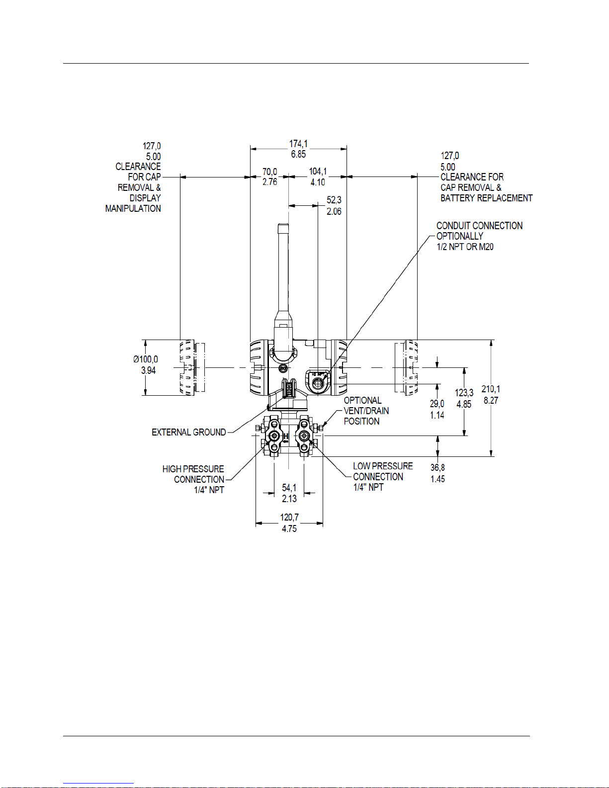
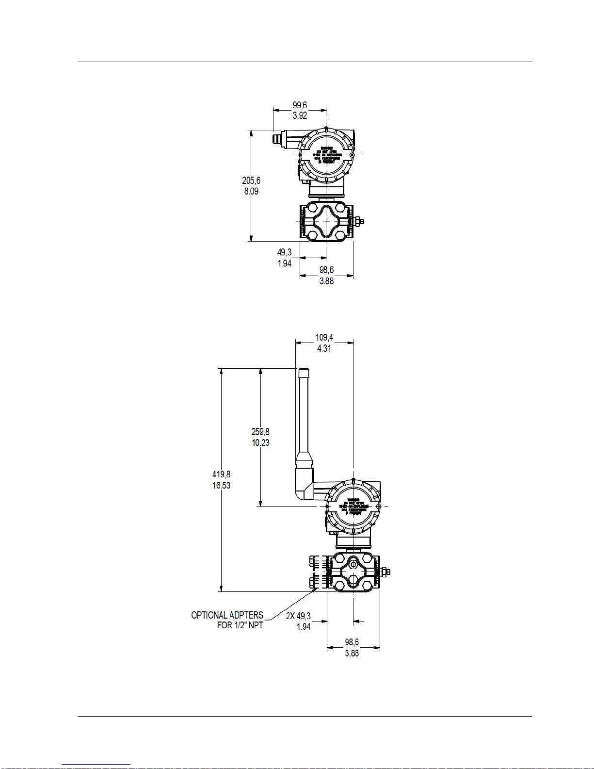
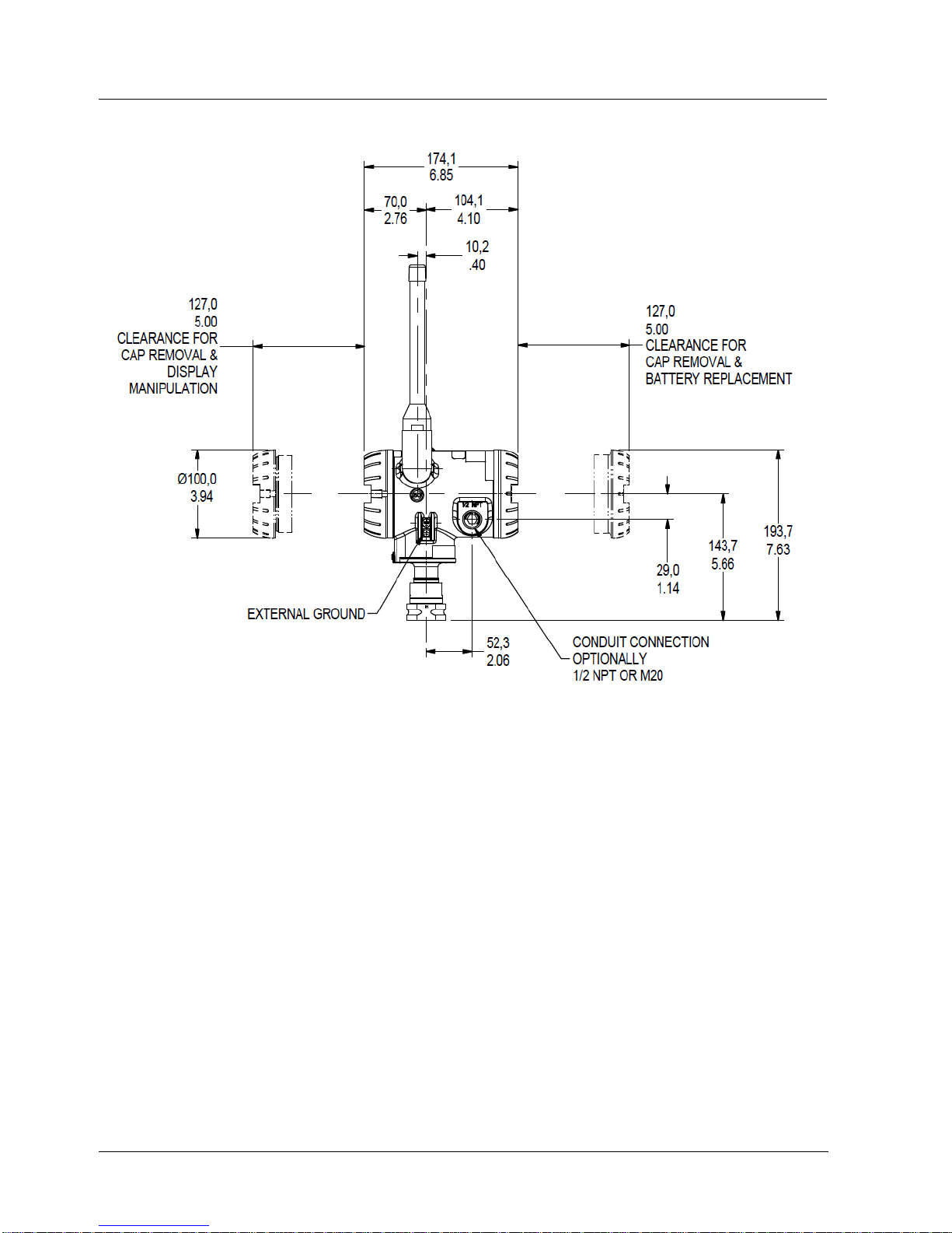
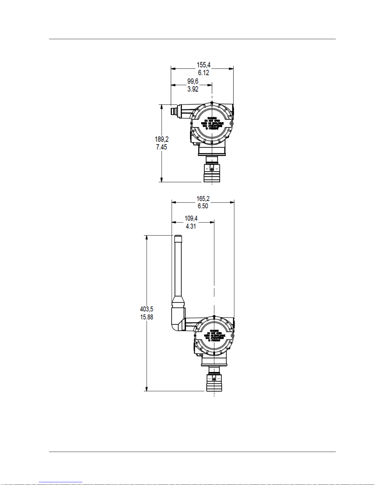
For Flange and Remote Seal transmitter dimensions, obtain appropriate installation drawing
using Installation drawing number tables in section 3, as a guide.
Page 24
3. Installation
3.4. Transmitter Weights and Dimensions
10 SmartLine Wireless User's Manual Revision 2
Dimensions
Figure 3-1: DP/DHGP Pressure transmitter dimensions unit mm/inch
Page 25
3. Installation
3.4. Transmitter Weights and Dimensions
Revision 2 SmartLine Wireles User's Manual 11
Figure 3-2: DP/DHGP Pressure antenna dimensions unit mm/inch
Page 26
3. Installation
3.4. Transmitter Weights and Dimensions
12 SmartLine Wireless User's Manual Revision 2
Figure 3-3: GP/AP Pressure transmitter dimensions unit mm/inch
Page 27
3. Installation
3.4. Transmitter Weights and Dimensions
Revision 2 SmartLine Wireles User's Manual 13
Figure 3-4: GP/AP Pressure antenna dimensions unit mm/inch
Page 28

3. Installation
3.5. Installation drawing number tables
14 SmartLine Wireless User's Manual Revision 2
3.5 Installation drawing number tables
If an installation drawing from the table below is required, please contact your local Honeywell
representative. Refer to Honeywell drawing numbers in Table 3-2 for detailed dimensions.
Abbreviated overall dimensions are also shown on the Specification Sheets for the transmitter
models, see References
This section assumes that the mounting dimensions have already been taken into account and the
mounting area can accommodate the Transmitter.
Table 3-2: Drawing numbers for pressure transmitters
DRAWING
DRAWING
NUMBER
INSTALLATION DRAWING STW700/800 PRESSURE, DP, SMV, DHGP, AND
DHAP
50136136
INSTALLATION DRAWING STW700/800 PRESSURE, INLINE (LAP AND LGP)
50136137
INSTALLATION DRAWING STW700/800 PRESSURE PSEUDO FLANGE
50136138
INSTALLATION DRAWING STW700/800 PRESSURE EXTENDED AND
FLUSH FLANGE
50136139
INSTALLATION DRAWING STW700/800 PRESSURE DP, DHGP AND DHAP
REMOTE SEAL
50136140
INSTALLATION DRAWING STW700/800 PRESSURE INLINE (LGP AND LAP)
REMOTE SEAL
50136141
INSTALLATION DRAWING STW700/800 PRESSURE PULP AND PAPER
50136142
INSTALLATION INSTRUCTIONS STW700/800 PRESSURE ANGLE
MOUNTING BRACKET
50136143
INSTALLATION INSTRUCTIONS STW700/800 PRESSURE FLAT MOUNTING
BRACKET
50136144
Page 29

3. Installation
3.6. Conduit / Cable Entries
Revision 2 SmartLine Wireles User's Manual 15
3.6 Conduit / Cable Entries
NOTICE
THIS PRODUCT IS SUPPLIED WITH PLASTIC DUST PLUGS IN THE
CONDUIT/CABLE GLAND ENTRIES. IT IS THE USERS
RESPONSIBILITY TO PROVIDE CABLE GLANDS, ADAPTORS AND/OR
BLANKING PLUGS SUITABLE FOR THE ENVIRONMENT IN WHICH THIS
PRODUCT IS INSTALLED. WHEN INSTALLED IN A HAZARDOUS
LOCATION THE CABLE GLANDS, ADAPTORS AND/OR BLANKING
PLUGS SHALL ADDITIONALLY BE SUITABLE FOR THE HAZARDOUS
LOCATION, THE PRODUCT CERTIFICATION AND ACCEPTABLE TO
THE AUTHORITY HAVING JURISDICTION FOR THE INSTALLATION
Summary
Table 3-3: Conduit entry plugs and cable glands for your transmitter.
Factory Part
No.
Description
Environmental
rating
Ambient
Hazardous Location
Certification
50000547-001
M20 Conduit
Plug
IP66-68, 4X,
6P
–40 – 85ºC
–40 – 185ºF
ATEX EEx de IIC
50021832-002
½ NPT Conduit
Plug
IP66-68, 4/4X,
6/6P
–40 – 85ºC
–40 – 185ºF
ATEX EEx d IIC;
CSAcus CL I, Zone 1, Ex/AEx d
IIC; CL I, Div 1 & 2, GP ABCD;
CL II, Div 1 & 2, GP EFG; CL III,
Div 1 & 2
50023232-001
M20 Cable
Gland
IP68
–40 – 100ºC
–40 – 212ºF
-----------------------------------
50023212-001
½ NPT Cable
Gland
IP68
–40 – 100ºC
–40 – 212ºF
-----------------------------------
Note: Torque conduit entry plugs, cable glands, or adapters to 32 Nm (24 lb-ft).
Page 30
3. Installation
3.7. Mounting Summary
16 SmartLine Wireless User's Manual Revision 2
3.7 Mounting Summary
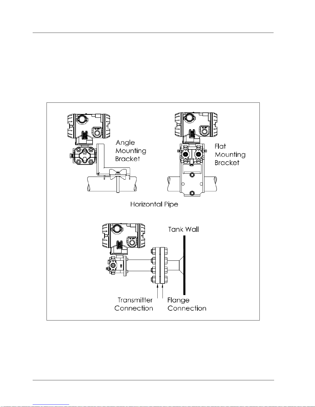
Transmitter models, except those with integral flanges, can be attached to a two-inch (50 millimeter)
vertical or horizontal pipe using Honeywell’s optional angle or flat mounting bracket; alternately you can
use your own bracket. Models with integral flanges are supported by the flange connection.
Figure 3-5 shows typical bracket-mounted and flange-mounted transmitter installations.
Figure 3-5: Typical Bracket Mounted and Flange Mounted Installations
Page 31
3. Installation
3.7. Mounting Summary
Revision 2 SmartLine Wireles User's Manual 17
Bracket Mounting Procedure
If you are using an optional bracket, start with Step 1. For an existing bracket, start with Step 2.
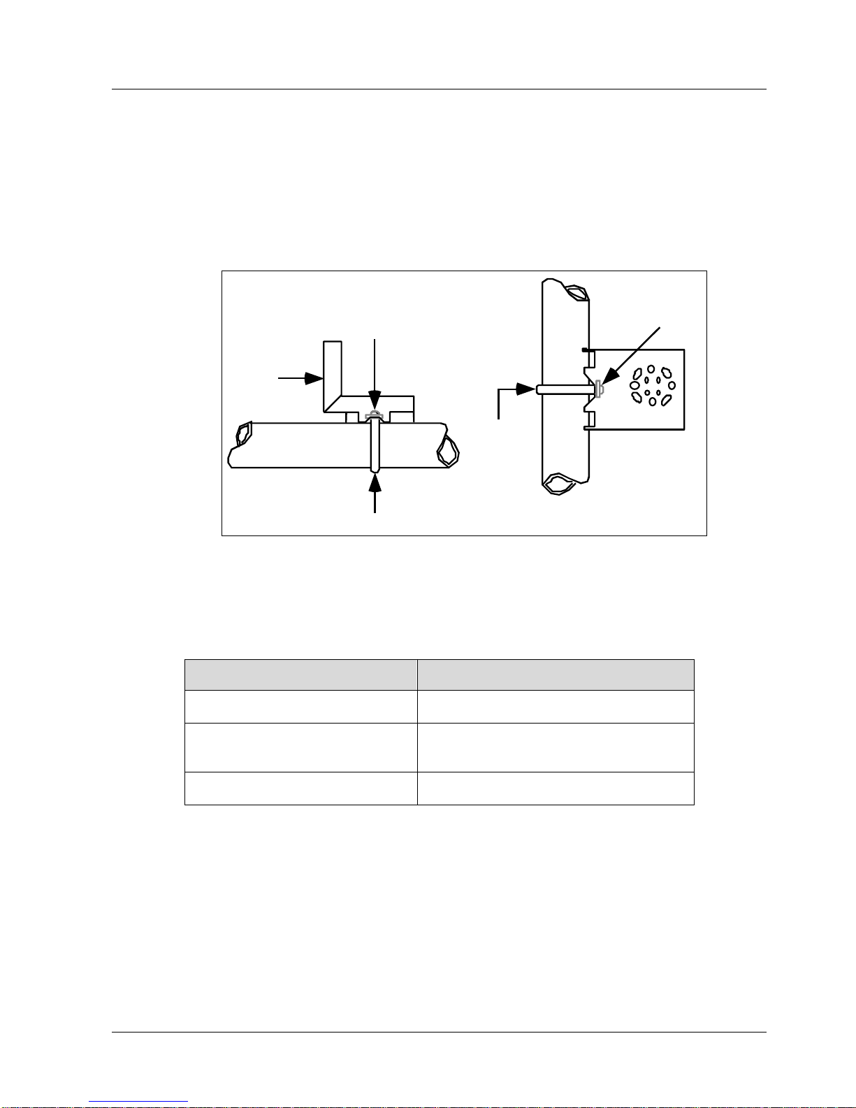
1. Refer to Figure 3-6. Position the bracket on a 2-inch (50.8 mm) horizontal or vertical pipe, and
install a “U” bolt around the pipe and through the holes in the bracket. Secure the bracket with
the nuts and lock washers provided.
Horizontal Pipe
Mounting
Bracket
Nuts and
Lockwashers
Nuts and
Lockwashers
U-Bolt
U-Bolt
Mounting
Bracket
Vertical Pipe
Figure 3-6: Angle Mounting Bracket Secured to a Horizontal or Vertical Pipe
2. Align the appropriate mounting holes in the Transmitter with the holes in the bracket. Use the
bolts and washers provided to secure the Transmitter to the bracket; see the following variations.
Transmitter Type
Use Hardware
DP with double-ended process
heads and/or remote seals
Alternate mounting holes in the ends of
the heads
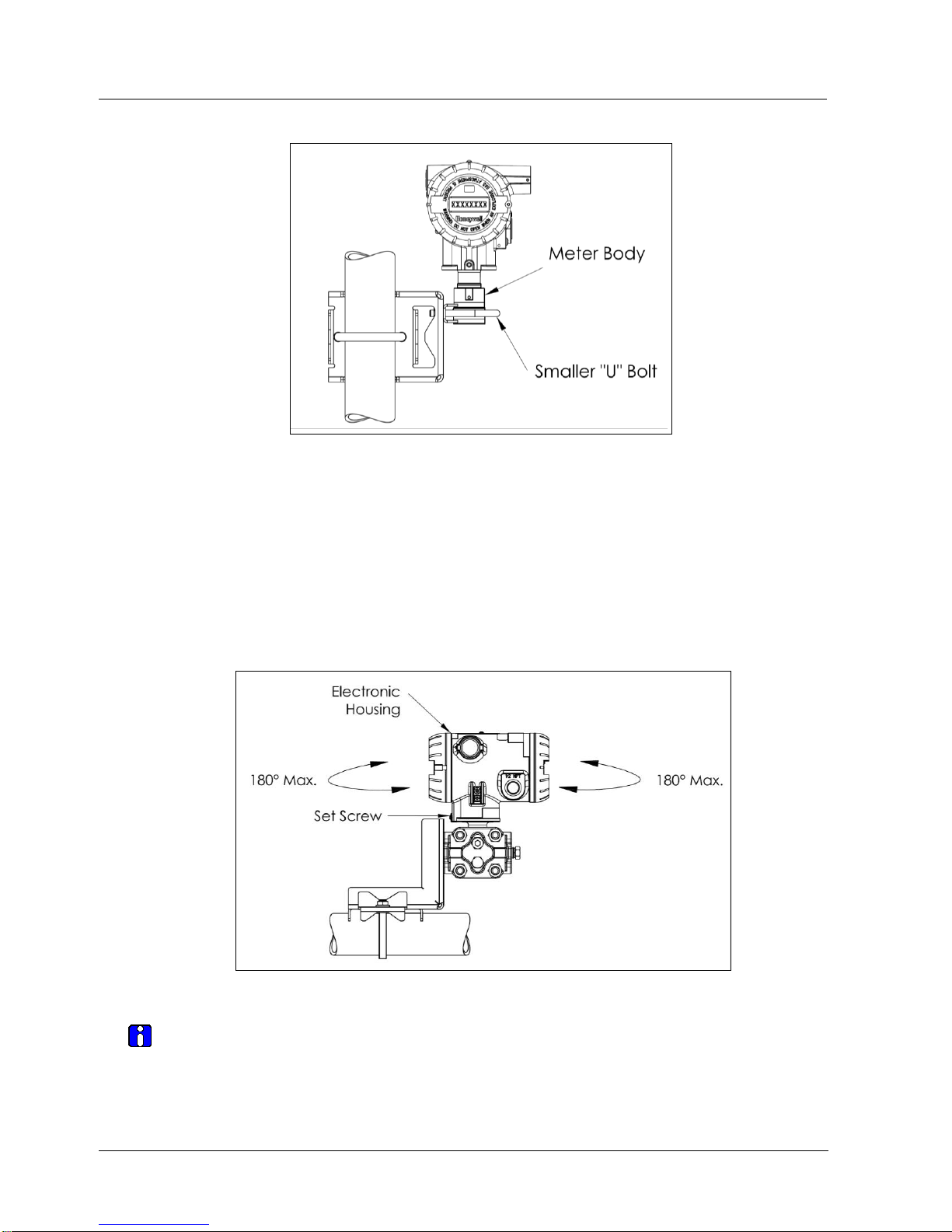
In-line GP and AP (STGWxxL and
STAWxxL)
The smaller “U” bolt provided to attach the
meter body to the bracket. See the
following example.
Dual-head GP and AP
Mounting holes in the end of the process
head.
EXAMPLE: Inline model mounted to an optional angle bracket. See
Figure 3-7.
Page 32
3. Installation
3.7. Mounting Summary
18 SmartLine Wireless User's Manual Revision 2
Figure 3-7: – Inline Model Mounted to an Optional Bracket
3. Loosen the set screw on the outside neck of the Transmitter one (1) full turn.
4. Rotate the Electronics housing a maximum of 180o left or right from the center to the position
you require, and tighten the set screw 8.9 to 9.7 lb-in (1.40 to 1.68 Nm), using a 4mm metric
socket head wrench. See Figure 3-8.
EXAMPLE: Rotating the Electronics Housing.
Figure 3-8: Rotating the Electronic Housing
The mounting position of absolute pressure models STAW822, STAW82L, or a draft range
model STDW810 is critical as the transmitter spans become smaller.
A maximum zero shift of 2.5 mmHg for an Absolute transmitter or 1.5 inches of water (inH2O)
for a Draft Range transmitter can result from a mounting position that is rotated 90o from the
Page 33

3. Installation
3.7. Mounting Summary
Revision 2 SmartLine Wireles User's Manual 19
vertical. A typical zero-shift of 0.12 mmHg or 0.20 inH2O can occur for a five (5)-degree
rotation from the vertical.
Page 34
3. Installation
3.7. Mounting Summary
20 SmartLine Wireless User's Manual Revision 2
Mounting Transmitters with Small Absolute or Differential Pressure Spans
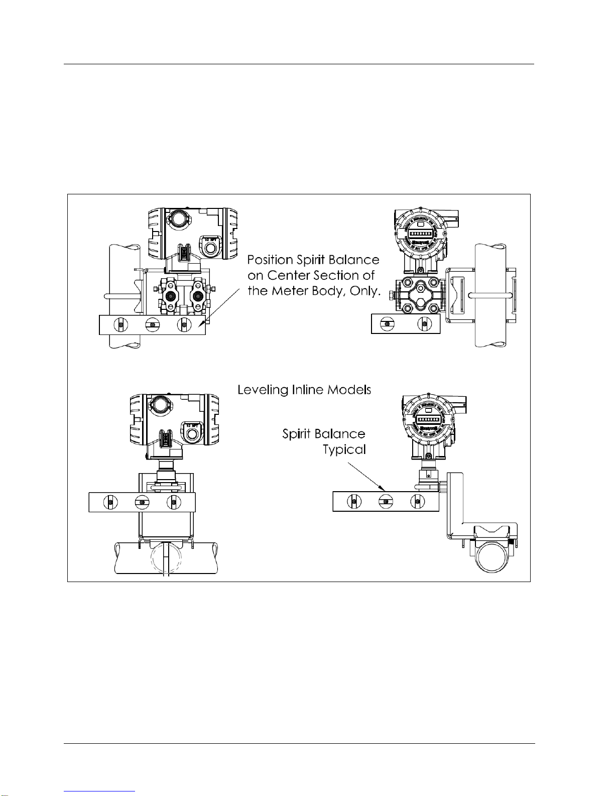
To minimize positional effects on calibration (zero shift), take the appropriate mounting
precautions for the respective transmitter model. For a model STAW822 or STAW82L, ensure
that the Transmitter is vertical when mounting it. You do this by leveling the Transmitter sideto-side and front-to-back. Figure 3-9 shows how to level a transmitter using a spirit level.
Figure 3-9: Using a Spirit Balance to Level a Transmitter
Page 35
3. Installation
3.7. Mounting Summary
Revision 2 SmartLine Wireles User's Manual 21
Flange Mounting
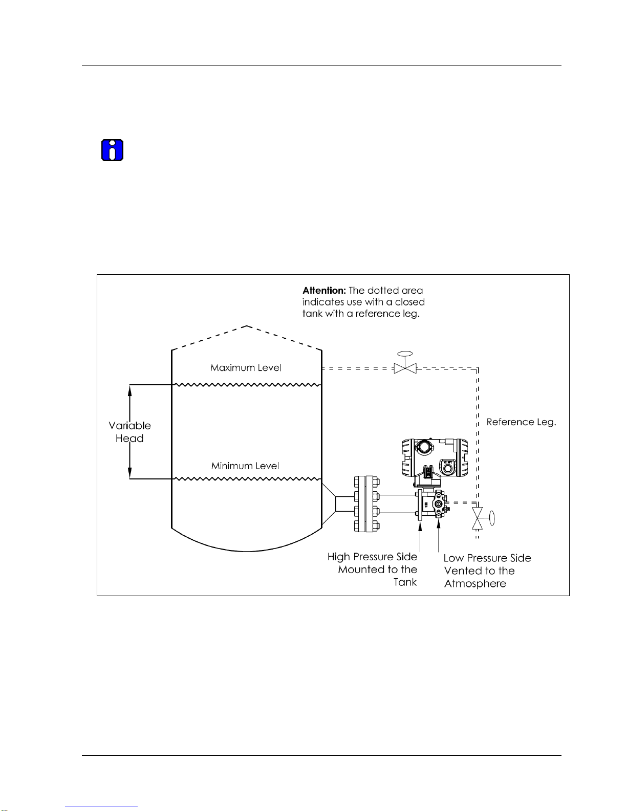
Figure 3-10 shows a typical tank-flange mount installation, with the transmitter flange mounted to the
pipe on the wall of the tank.
On insulated tanks, remove enough insulaiton to accommodate the flange extension.
When flange-mounting to a tank, note the following:
The End User is responsible for providing a flange gasket and mounting hardware suitable for the
Transmitter service conditions.
To prevent performance degradation in extended-mount flanged transmitters, ensure that
sufficient clearance exists in front of the sensing diaphragm body.
Figure 3-10: Tank-Flange Mounted Transmitter
Page 36
3. Installation
3.7. Mounting Summary
22 SmartLine Wireless User's Manual Revision 2
Remote Diaphragm Seal Mounting Information
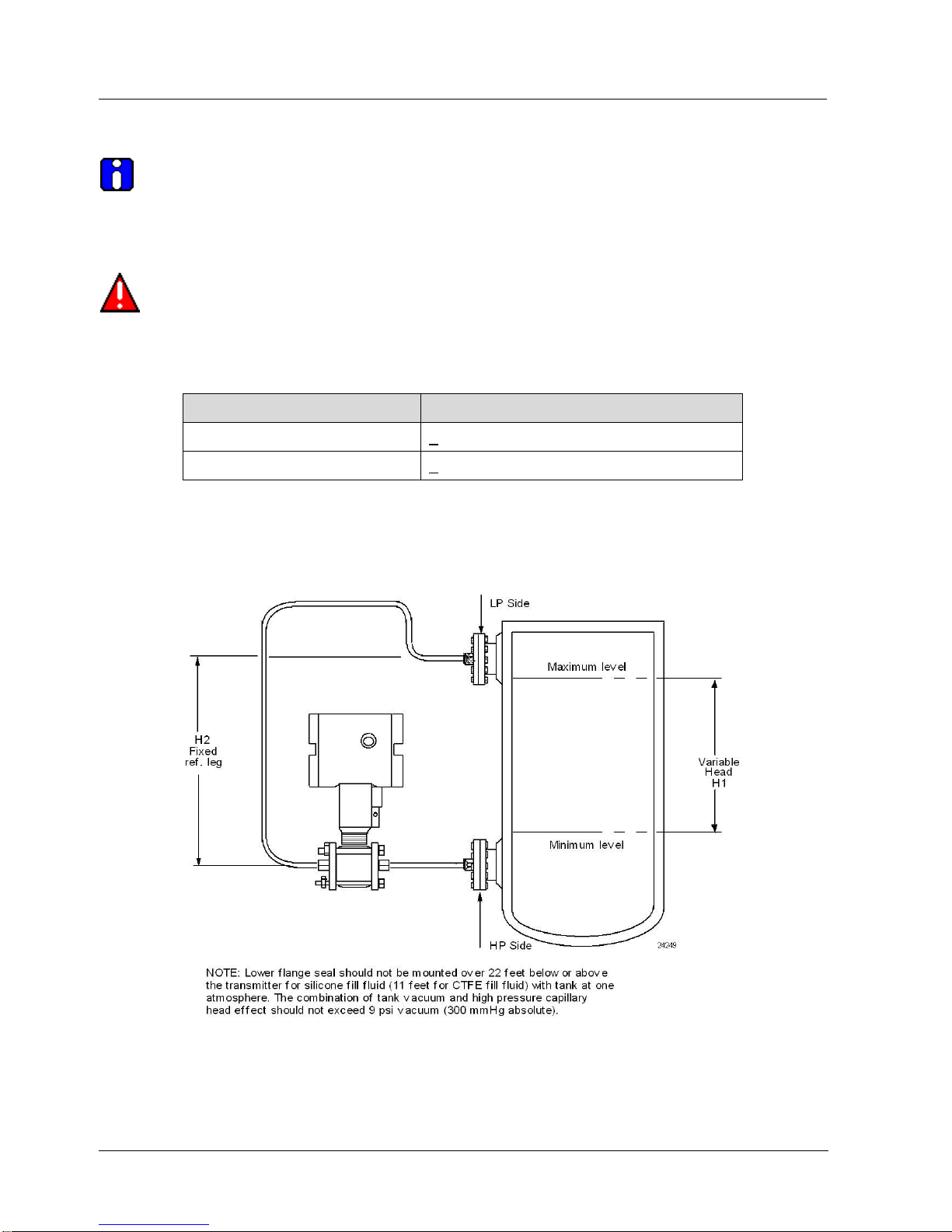
The combination of tank vacuum and high pressure capillary head effect should not
exceed nine (9) psi (300 mmHg) absolute. For insulated tanks, be sure to remove enough
insulation to accommodate the flange extension. The end user is responsible for supplying a
flange gasket and mounting hardware suitable for the service condition of the Transmitter.
Mount the transmitter flanges within the limits in for the fill fluid in the capillary tubes, with
a tank at one (1) atmosphere.
Table 3-4: Flange Mounting Guidelines
Fill Fluid
Mount the Flange…
Silicone 200 Oil
<22 feet (6.7 meters) below the Transmitter
Chlorotrifluoroethylene (CTFE)
<11 feet (3.4 meters) below the Transmitter
Refer to
Figure 3-11 for a representative remote diaphragm seal installation. Mount the transmitter at a remote
distance determined by the length of the capillary tubing.
Figure 3-11: Representative Remote Diaphragm Seal Transmitter Installation
Page 37

3. Installation
3.8. Piping the SmartLine Wireless Transmitter
Revision 2 SmartLine Wireles User's Manual 23
Depending on transmitter model, connect the remote seal to the tank shown below.
Table 3-5: Remote Diaphragm Mounting Details
Transmitter
Model
Connect the Remote Seal on ….
Variable Head
Fixed or Constant Head
STRW82D
Transmitter High Pressure (HP)
Side to tank wall lower flange
mounting.
Transmitter Low Pressure (LP) side to tank
wall upper flange.
STRW83D
Transmitter Low Pressure (LP)
Side to tank wall lower flange
mounting.
Transmitter Low Pressure (LP) side to tank
wall upper flange. OR High Pressure (HP) side
to tank wall upper flange.
3.8 Piping the SmartLine Wireless Transmitter
Piping Arrangements
Piping arrangements vary depending upon process measurement requirements and the transmitter model.
For example, a differential pressure transmitter comes with double-ended process heads with ¼-inch
NPT connections, which can be modified to accept ½-inch NPT through optional flange adapters. Gauge
pressure transmitters are available with various connections for direct mounting to a process pipe.
A ½-inch, schedule 80, steel pipe is commonly used for transmitter integration into a process
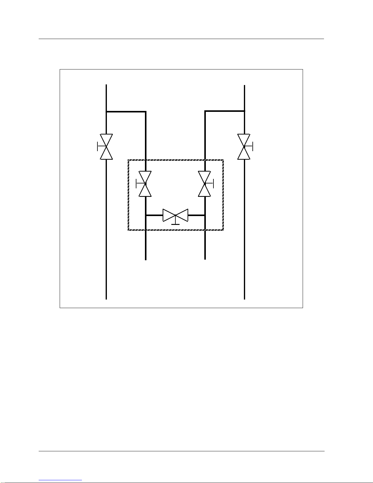
system. Many piping arrangements use a three-valve manifold to connect the process piping to
the transmitter. A manifold makes it easy to install and remove or re-zero a transmitter without
interrupting the process. A manifold also accommodates the installation of blow-down valves to
clear debris from pressure lines.
Figure 3-12 represents a typical piping arrangement using a three-valve manifold and blow-down
lines for a differential pressure transmitter being used to measure flow.
Page 38
3. Installation
3.8. Piping the SmartLine Wireless Transmitter
24 SmartLine Wireless User's Manual Revision 2
Blow-Down
Valve
3-Valve
Manifold
To Upstream TapTo Downstream Tap
To Low Pressure
Side of Transmitter
To High Pressure
Side of Transmitter
Blow-Down
Valve
Blow-Down
Piping
To WasteTo Waste
Blow-Down
Piping
Figure 3-12: Typical 3-Valve Manifold with Blow-Down Piping
Page 39
3. Installation
3.8. Piping the SmartLine Wireless Transmitter
Revision 2 SmartLine Wireles User's Manual 25
Suggestions for Transmitter Location
Suggests connections based on what is being processed by the system.
Table 3-6: Suggested Connection Locations
Process
Suggested Location
Description
Gases
Above the gas line.
The condensate drains away from the Transmitter.
Liquids
Below but near the elevation of
the process connection.
This minimizes that static head effect of the
condensate.
Level with or above the process
connection.
This requires a siphon to protect. the Transmitter from
process steam. The siphon retains water as a fill fluid.
1. For liquid or steam, the piping should slope a minimum of 25.4 mm (1 inch) per 305 mm (1 foot).
2. Slope the piping down toward the transmitter if it is below the process connection to allow the
bubbles to rise back into the piping through the liquid.
3. If the transmitter is located above the process connection, the piping should rise vertically above
the Transmitter. In this case, slope down toward the flow line with a vent valve at the high point.
4. For gas measurement, use a condensate leg and drain at the low point (freeze protection may be
required here).
ATTENTION Care must be taken when installing transmitters on hot processes.
The operating temperature limits for the device (see section 3.3) must not be exceeded.
Impulse piping may be used to reduce the temperature of the process that comes into contact
with the transmitter meter body. As a general rule there is a 56C drop (100 F) in the
temperature of the process for every foot of ½ inch uninsulated piping.
General Piping Guidelines
When measuring fluids that contain suspended solids, install permanent valves at regular
intervals to blow-down piping.
Blow-down all lines on new installations with compressed air or steam, and flush them with process
fluids (where possible) before connecting these lines to the transmitter meter body.
Verify that the valves in the blow-down lines are closed tightly after the initial blow-down
procedure and each maintenance procedure thereafter.
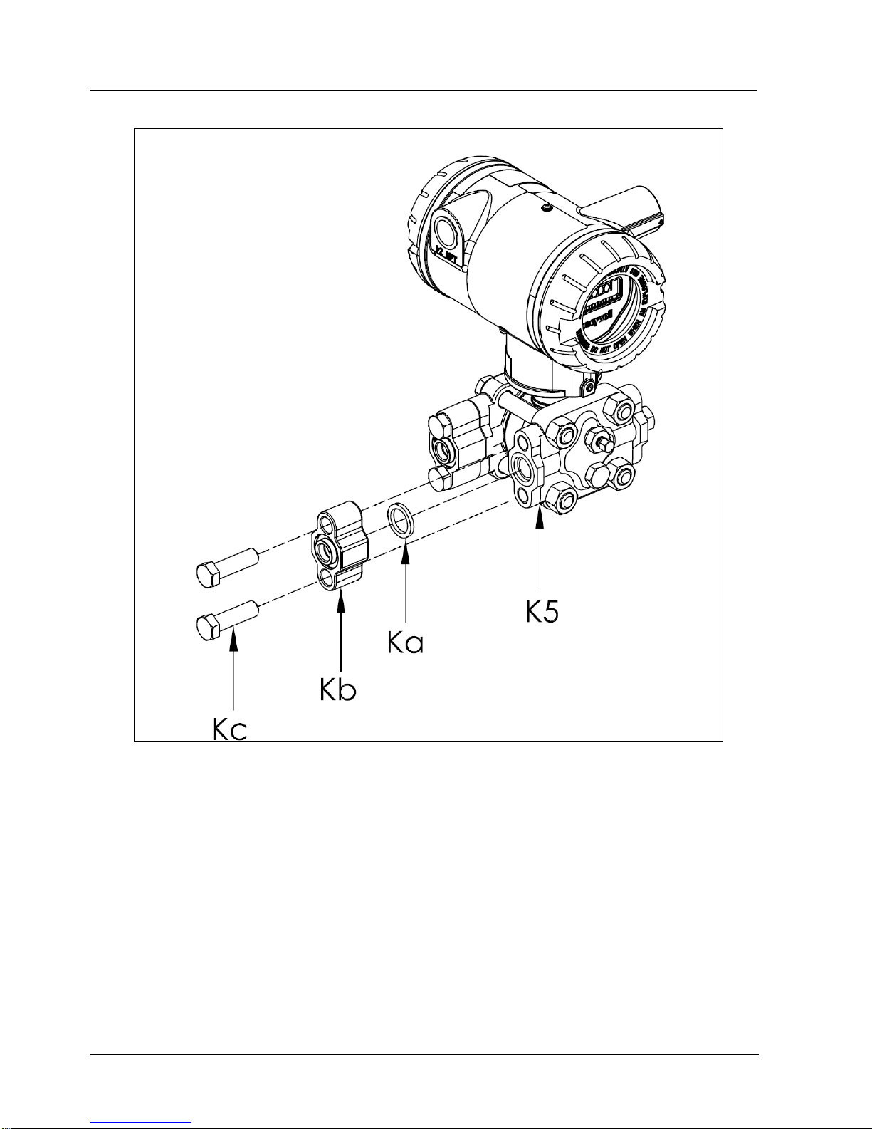
Procedure to Install Flange Adapters
The following procedure provides the steps for removing and replacing an optional flange adapter on the
process head. See Figure 3-13.
This procedure does not require that the meter body be removed from the Electronics
Housing. If flange adapters are being replaced with parts from other kits (for example, process
heads), follow the procedures for the kits and incorporate the following procedure.
NOTE: The threaded hole in each Flange Adapter is offset from center. To ensure proper
orientation for re-assembly, note the orientation of the offset relative to each Process Head
before removing any adapter.
Page 40
3. Installation
3.8. Piping the SmartLine Wireless Transmitter
26 SmartLine Wireless User's Manual Revision 2
Figure 3-13: Flange Adapter Removal and Replacement
Refer to the instructions included with the kit for removal and replacement procedures.
Page 41
3. Installation
3.9. Rotate transmitter housing
Revision 2 SmartLine Wireles User's Manual 27
3.9 Rotate transmitter housing
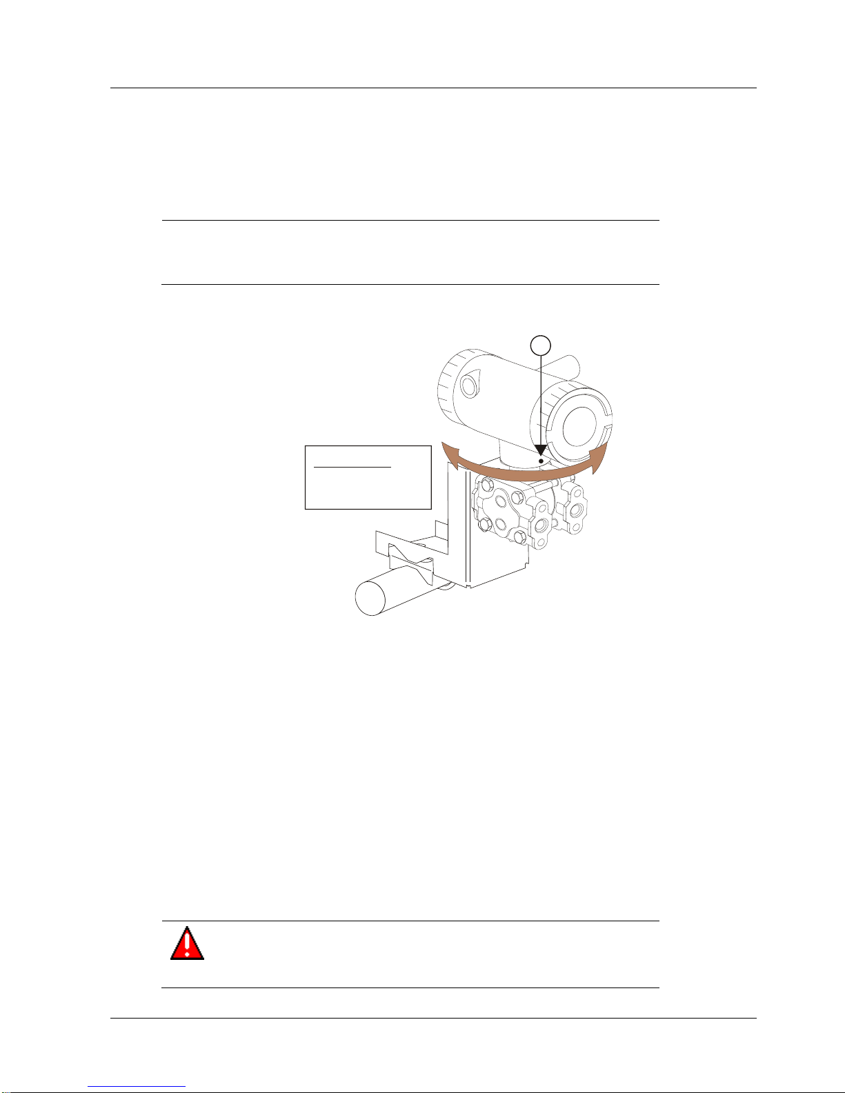
You can rotate the transmitter for better viewing, access, or antenna position. Loosen set screw
(see A in Figure 3-14) on outside neck of transmitter one full turn. Rotate transmitter housing up
to 180 degrees in either direction to desired position.
CAUTION
Do not rotate the housing past 180 degrees in any direction or you
could damage the internal wiring.
Tighten set screw.
CAUTION:
Do not rotate
more than 180
0
A
Figure 3-14: Rotating transmitter housing
3.10 Rotate display
If the transmitter’s mounting is such that the display is not horizontal, you can rotate the display
90 degree clockwise or counterclockwise to provide horizontal viewing.
Tools required
#1 Phillips Screwdriver or 1/8” Slotted Screwdriver
Torque Screwdriver
1.5 mm hex key
Procedure
WARNING
Risk of death or serious injury by explosion. Do not open transmitter
enclosure when an explosive gas atmosphere is present.
Page 42
3. Installation
3.10. Rotate display
28 SmartLine Wireless User's Manual Revision 2
CAUTION
Take precautions against electrostatic discharge to prevent damaging the
display/sensor module.
Display adjustment
Step
Action
1
Honeywell recommends that the transmitter be removed from service and moved to a
clean area before servicing.
2
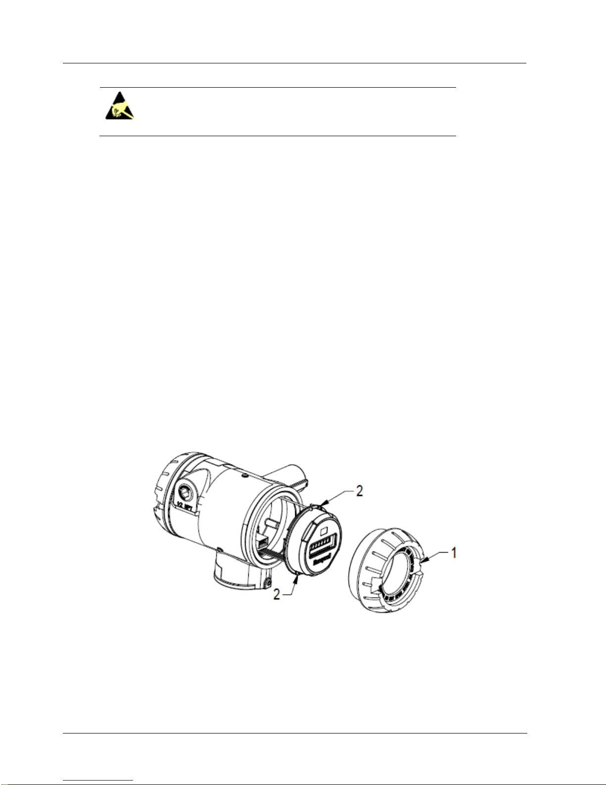
Loosen the M3 locking set screw on the display end-cap. See item 1 in Figure 3-15.
Unscrew and remove the end cap.
3
Loosen the two captive screws on the display/sensor module. See items 2 in Figure
3-15.
4
Rotate the display 90 degrees in either direction so the screws line up with the
threaded holes. Do not rotate more than 90 degrees or you could damage the wires
behind the display.
5
There are two connectors on the back of the display/sensor module, J4 and J5, either
of which can be used to connect to the meter body cable. If required, move the meter
body cable to the other position.
6
Re-attach the display’s two captive screws. Tighten to 0,4 – 0,6 Nm (3.5 – 5.3 lb-in.).
7
Replace end cap and tighten M3 locking screw.
Figure 3-15: Display rotation
Page 43
3. Installation
3.11. Antenna adjustment and mounting
Revision 2 SmartLine Wireles User's Manual 29
3.11 Antenna adjustment and mounting
Requirements
Radio installation requirements
ATTENTION
Professional Installation is required to insure conformity with Federal Communications
Commission (FCC) in the USA, Industry Canada (IC) in Canada and the Radio and
Telecommunications Terminal Equipment Directive, 1999/5/EC (R&TTE), in the European
Union (EU).
Professional installation is required for the selection and installation of approved antennas and
setup of the maximum allowable radiated power from the SmartLine Wireless Transmitter as
configured for the particular installation site.
The antenna used for this transmitter must be installed to provide a separation distance of at
least 20 cm (8 inches) from all persons and must not be co-located or operating in conjunction
with any other antenna or transmitter.
For remote antenna, see antenna installation requirements to satisfy FCC RF exposure
requirements.
ATTENTION
Federal Communications Commission (FCC):
The SmartLine Wireless Transmitters comply with part 15 of the FCC rules. Operation is
subject to the following two conditions: (1) this device may not cause harmful interference, and
(2) this device must accept any interference received, including interference that may cause
undesired operation.
Industry Canada (IC):
The installer of this radio equipment must ensure that the antenna is located or pointed such
that it does not emit RF fields in excess of Health Canada limits for the general population;
consult Safety Code 6, obtainable from Health Canada’s web site www.hc-sc.gc.ca/rpb.
Integral antenna
WARNING
POTENTIAL ELECTROSTATIC CHARGING HAZARD
The integrally mounted antenna shroud may have a surface resistance
greater than 1Gohm per square. When the SmartLine transmitter is installed
in potentially hazardous locations care should be taken not to electrostatically
charge the surface of the antenna shroud by rubbing the surface with a cloth,
or cleaning the surface with a solvent. If electrostatically charged, discharge
of the antenna shroud to a person or a tool could possibly ignite a
surrounding hazardous atmosphere.
Page 44
3. Installation
3.11. Antenna adjustment and mounting
30 SmartLine Wireless User's Manual Revision 2
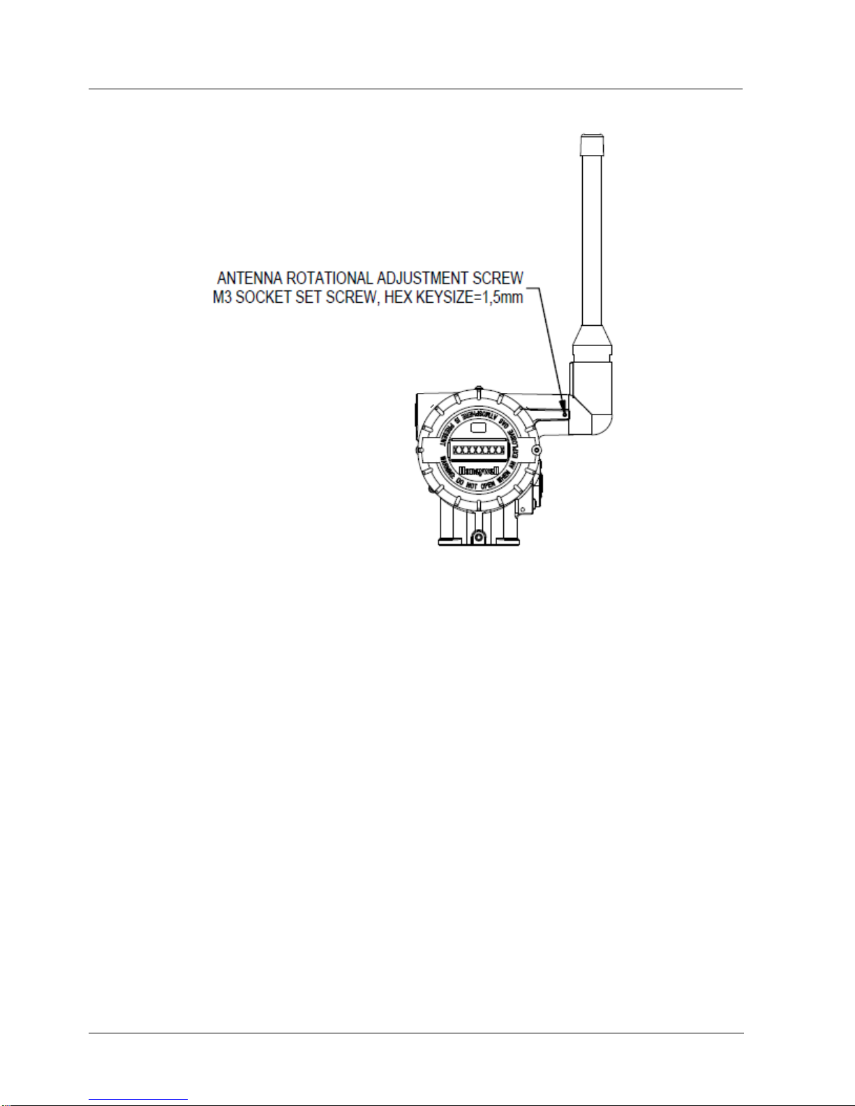
Figure 3-16: Elbow antenna adjustment
If your model has the integral elbow antenna you can adjust it to improve reception. Typically,
pointed straight up gives best performance but your installation may vary. Loosen the 1.5mm set
screw located near the antenna base. Rotate antenna for best reception. Do not rotate antenna
more than 180 degrees either direction or you could damage internal wiring. Tighten set screw
shown in Figure 3-16.
Page 45
3. Installation
3.12. Remote antenna
Revision 2 SmartLine Wireles User's Manual 31
3.12 Remote antenna
Outdoor installation warnings
WARNING
LIVES MAY BE AT RISK! Carefully observe these instructions and any special instructions
that are included with the equipment you are installing.
WARNING
Contacting power lines can be lethal.
Look over the site before beginning any installation, and anticipate possible hazards,
especially these:
Make sure no power lines are anywhere where possible contact can be made. Antennas,
masts, towers, guy wires or cables may lean or fall and contact these lines. People may be
injured or killed if they are touching or holding any part of equipment when it contacts electric
lines. Make sure there is NO possibility that equipment or personnel can come in contact
directly or indirectly with power lines.
Assume all overhead lines are power lines.
The horizontal distance from a tower, mast or antenna to the nearest power line should be at
least twice the total length of the mast/antenna combination. This will ensure that the mast will
not contact power if it falls either during installation or later.
WARNING
To avoid falling, use safe procedures when working at heights above ground.
Select equipment locations that will allow safe, simple equipment installation.
Don’t work alone. A friend or co-worker can save your life if an accident happens.
Use approved non-conducting ladders and other safety equipment. Make sure all equipment is
in good repair.
If a tower or mast begins falling, don’t attempt to catch it. Stand back and let it fall.
If anything such as a wire or mast does come in contact with a power line, DON’T TOUCH IT
OR ATTEMPT TO MOVE IT. Instead, save your life by calling the power company.
Don’t attempt to erect antennas or towers on windy days.
WARNING
MAKE SURE ALL TOWERS AND MASTS ARE SECURELY GROUNDED, AND
ELECTRICAL CABLES CONNECTED TO ANTENNAS HAVE LIGHTNING ARRESTORS.
This will help prevent fire damage or human injury in case of lightning, static build-up, or short
circuit within equipment connected to the antenna.
The base of the antenna mast or tower must be connected directly to the building protective
ground or to one or more approved grounding rods, using 1 OAWG ground wire and
corrosion-resistant connectors.
Refer to the National Electrical Code for grounding details.
Lightning arrestors for antenna feed coaxial cables are available from HyperLink
Technologies, Inc.
Page 46
3. Installation
3.12. Remote antenna
32 SmartLine Wireless User's Manual Revision 2
WARNING
If a person comes in contact with electrical power, and cannot move:
DON’T TOUCH THAT PERSON, OR YOU MAY BE ELECTROCUTED.
Use a non-conductive dry board, stick or rope to push or drag them so they no longer are in
contact with electrical power.
Once they are no longer contacting electrical power, administer CPR if you are certified, and
make sure that emergency medical aid has been requested.
Choosing a Mounting Location
The location of the antenna is important. Objects such as metal columns, walls, etc. will reduce
efficiency. Best performance is achieved when antennas for both Multinodes and SmartLine
Transmitters (Leaf Nodes) are mounted at the same height and in a direct line of sight with no
obstructions. If this is not possible and reception is poor, you should try different mounting
positions to optimize reception.
Antennas should be mounted clear of any obstructions to the sides of the radiating element. If the
mounting location for an omnidirectional antenna is on the side of a building or tower, then the
antenna pattern will be degraded on the building or tower side.
Site Selection
Before attempting to install your antenna, think where you can best place the antenna for safety
and performance.
Follow these steps to determine a safe distance from wires, power lines, and trees.
Step
Action
1
Measure the height of your antenna.
2
Add this length to the length of your tower or mast and then double this total for the minimum
recommended safe distance.
CAUTION
If you are unable to maintain this safe distance, stop and get professional help.
Page 47

3. Installation
3.12. Remote antenna
Revision 2 SmartLine Wireles User's Manual 33
Generally, the higher your antenna is above the ground, the better it performs. Good practice is to
install your antenna about 5 to 10 feet (1.5 to 3 meters) above the roof line and away from all
power lines and obstructions. If possible, find a mounting place directly above your wireless
device so that the lead-in cable can be as direct as possible.
Mounting the Antenna
Antennas are provided with a mast mounting kit consisting of a mounting bracket and two U-bolt
clamps. This kit allows you to mount the antenna to masts with outside diameters (O.D.) from
1.25 inches (3.2 centimeters) to 2 inches (5.1 centimeters). Honeywell recommends that a 1.5
inch (3.8 centimeter) or larger tubing mast be used.
Omnidirectional antennas are vertically polarized. It is very important to mount the antenna in a
vertical (not leaning) position for optimal performance.
Follow these steps to mount the antenna on a mast.
Step
Action
1
Assemble your new antenna on the ground at the installation site. See the instructions on the
following pages for your type of antenna.
2
Attach the antenna to the mast and connect its coaxial cable while you are on the ground, using
the mounting kit provided with the antenna. Tighten cables by hand only; do not use tools or
you could overtighten. After the cable is attached to the antenna, make sure that the
connections are sealed (if outdoors) the prevent moisture and other weathering elements from
effecting performance. Honeywell recommends using a weathering tape (such as Coax-Seal)
for outdoor connections. Silicon sealant or electrical tape is not recommended for sealing out
door connections.
3
Using tie-wraps (cable ties), secure the coax cable to the mast, using a tie-wrap every ten to
twelve inches (25 to 30 cm).
4
Follow standard strain relief practice when installing the antenna cable. Avoid excessive strain,
bending, kinks, or crushing (stepping on or placing any weight on cable) before, during or after
the coax cable is secured in its final position.
5
Make sure the mast does not fall the "wrong way" should you lose control as you raise or take
down the mast. Use a durable non-conductive rope. Have an assistant tend to the rope; ready
to pull the mast clear of any hazards (such as power lines) should it begin to fall.
6
If the installation will use guy wires:
Install guy anchor bolts.
Estimate the length of guy wire and cut it before raising the mast.
Attach guy wires to a mast using guy rings.
7
Carefully connect the antenna and mast assembly to its mounting bracket and tighten the clamp
bolts.
In the case of a guyed installation, you must have at least one assistant to hold the mast upright
while the guy wires are attached and tightened to the anchor bolts.
8
Attach the provided self-adhering "DANGER" label at eye level on the mast.
9
Install ground rods to remove any static electricity buildup and connect a ground wire to the
mast and ground rod. Use ground rods designed for that purpose; do not use a spare piece of
pipe.
Page 48
3. Installation
3.12. Remote antenna
34 SmartLine Wireless User's Manual Revision 2
Step
Action
10
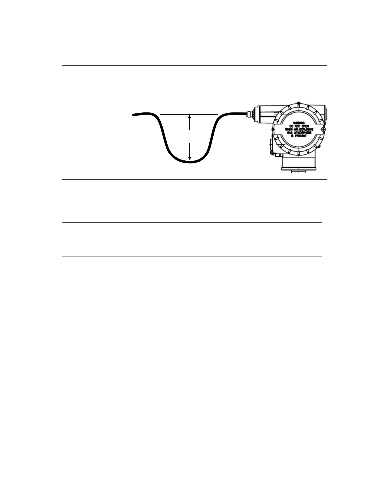
When attaching the coax cable to the SmartLine Wireless transmitter, it is recommended that a
drip loop with a radius of at least 12 inches (30 cm) be formed close to the SmartLine
transmitter. This will minimize ice and water buildup on the transmitter itself. Tighten cables by
hand only; do not use tools or you could overtighten.
To lightning
arrestor & antenna
12”/30cm
Drip loop
Directional mounting procedure
Step
Action
1
Secure mast mounting bracket to mast as shown using 2 U-bolts and supplied hardware.
2
Attach antenna to mast mounting bracket as shown using supplied hardware.
3
Adjust antenna to desired tilt and lock into place using the antenna tilt adjustment nut.
Page 49
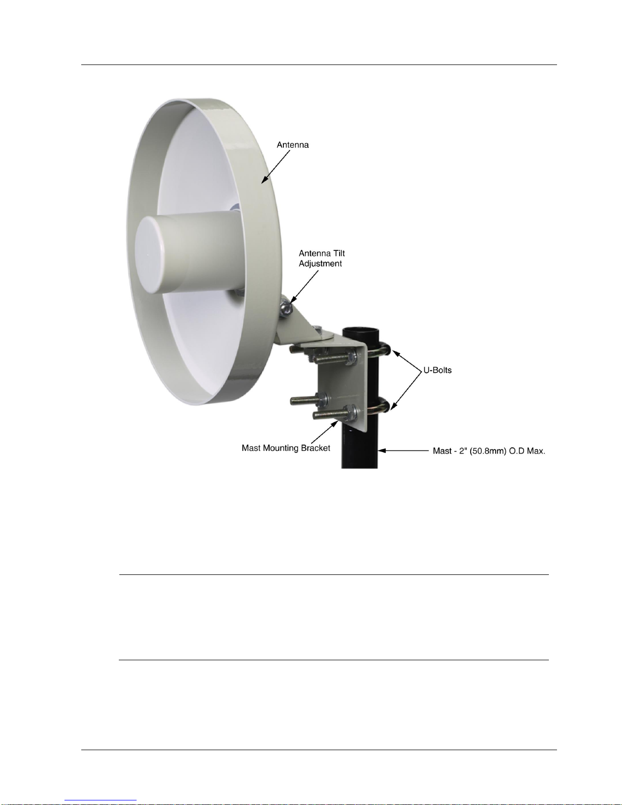
3. Installation
3.12. Remote antenna
Revision 2 SmartLine Wireles User's Manual 35
Figure 3-17: Directional antenna mounting
Omnidirectional mounting procedure
Step
Action
1
Secure mast mounting bracket to mast as shown using 2 U-bolts and supplied hardware.
2
Remove antenna mounting bolt and washer from antenna base.
3
Insert antenna into mounting bracket and secure with washer and antenna mounting bolt. Do
not overtighten.
4
Any drain holes in the antenna base must be kept clear for proper operation.
Page 50
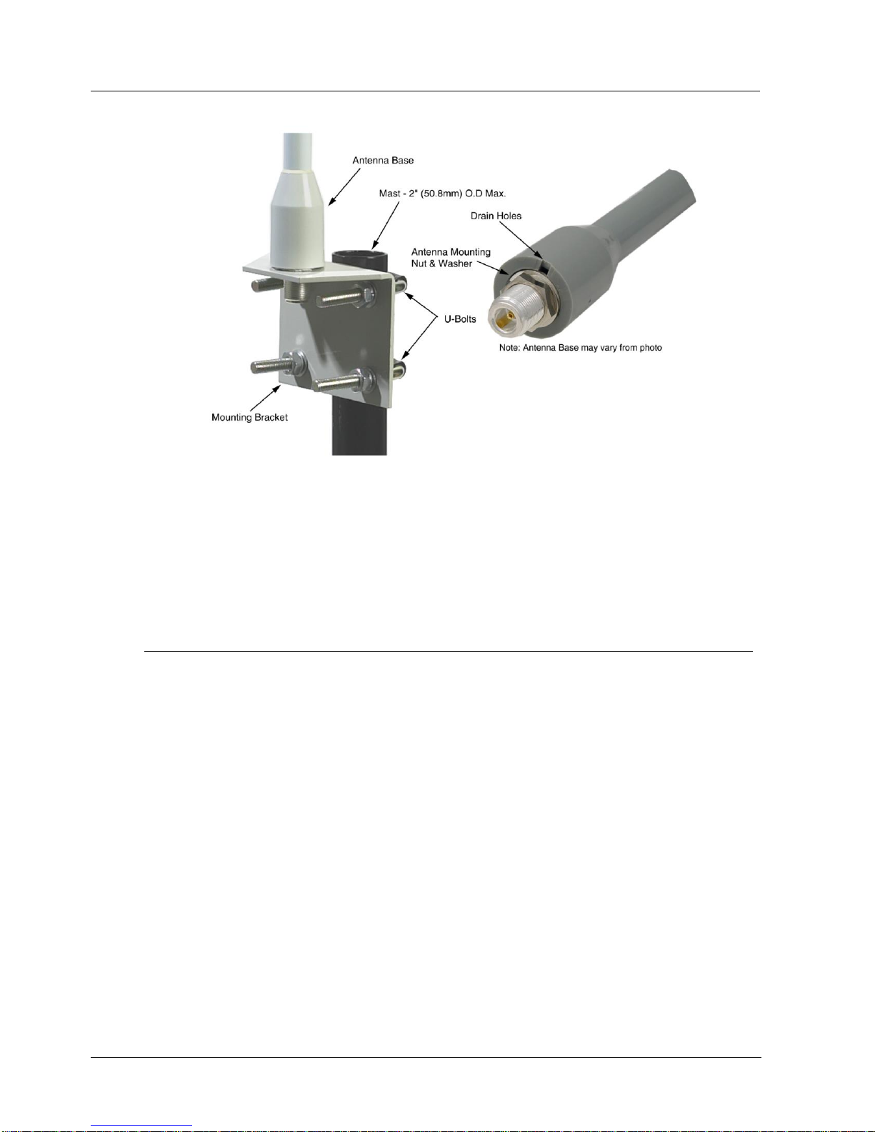
3. Installation
3.12. Remote antenna
36 SmartLine Wireless User's Manual Revision 2
Figure 3-18: Omnidirectional antenna mounting
Grounding the antenna
Follow these guidelines to ground the antenna in accordance with national electrical code
instructions.
Step
Action
1
Use No. 10 AWG copper or No. 8 or larger copper-clad steel or bronze wire as ground wires
for both mast and lead-in. Securely clamp the wire to the bottom of the mast.
2
Secure the lead-in wire to a lightning arrestor and mast ground wire to the building with standoff insulators spaced from 4 feet (1.2 meters) to 8 feet (1.8 meters) apart.
3
Using coaxial cable, connect the antenna base to the transmitter’s remote antenna connector
(located at top right as you face the transmitter display). Antenna cable shield is bonded to
earth ground via either the transmitter earth ground connection and/or by the lightning arrestor
earth ground connection. The lightning arrestor must be bonded to earth ground in order to
function properly. Tighten cables by hand only; do not use tools or you could overtighten.
See section 3 for cable types and connection information.
4
If the coax cable is to enter a building, then the lightning arrestor should be mounted as close
as possible to where the lead-in wire enters the building. The lightning arrestor sold by
Honeywell features a bulkhead N-Female connector with a rubber “O”-ring seal which can be
used for mounting through an enclosure wall. The lightning arrestor can also be mounted
using the included stainless steel mounting bracket. Both connector ports of the lightning
arrestor provide equal protection no matter which way it is installed. Either port can face the
antenna and either port can face the Transmitter.
5
Drill a hole in the building's wall as close as possible to the equipment to which you will
connect the lead-in cable.
Page 51
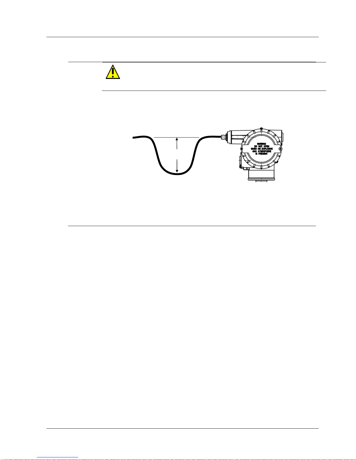
3. Installation
3.12. Remote antenna
Revision 2 SmartLine Wireles User's Manual 37
Step
Action
CAUTION
There may be wires in the wall. Before drilling check that the area is clear of any
obstructions or other hazards.
6
Pull the cable through the hole and form a drip loop on the outside close to where the cable
enters the building. The drip loop should have a radius of at least 12 inches (30 cm).
To lightning
arrestor & antenna
12”/30cm
Drip loop
7
Thoroughly waterproof the lead-in area.
8
Connect the lead-in cable to the SmartLine Transmitter. Tighten cables by hand only; do not
use tools or you could overtighten.
Page 52
4. Start up
4.1. Battery Power Option
38 SmartLine Wireless User's Manual Revision 2
4. Start up
4.1 Battery Power Option
Install/Replace batteries
WARNING
Risk of death or serious injury from explosion or fire.
When not in use the Battery Pack must be stored in a non Hazardous
Area
Do not change batteries in an explosive gas atmosphere.
The batteries used in this device may present a risk of fire or chemical
burn if mistreated. Do not recharge, disassemble, heat above 100°C
(212°F), or incinerate.
When installing batteries, do not snag the battery terminal on the clip or
the battery may be damaged. Do not apply excessive force.
Do not drop. Dropping the battery may cause damage. If a battery is
dropped, do not install the dropped battery into the transmitter. Dispose
of dropped battery promptly per local regulations or per the battery
manufacturer’s recommendations.
ATTENTION
Both batteries must be the same model from the same manufacturer. Mixing old
and new batteries or different manufacturers is not permitted.
Use only the following 3.6V lithium thionyl chloride (Li-SOCl2) batteries (nonrechargeable), size D. No other batteries are approved for use in SmartLine
Wireless Transmitters.
Xeno Energy XL-205F
Eagle Picher PT-2300H
Tadiran TL-5930/s
Tadiran GmbH, SL-2780 (Not approved by FM or CSA)
Honeywell p/n 50026010-501 (Two 3.6V lithium thionyl chloride batteries)
Honeywell p/n 50026010-502 (Four 3.6V lithium thionyl chloride batteries)
Honeywell p/n 50026010-503 (Ten 3.6V lithium thionyl chloride batteries)
Page 53
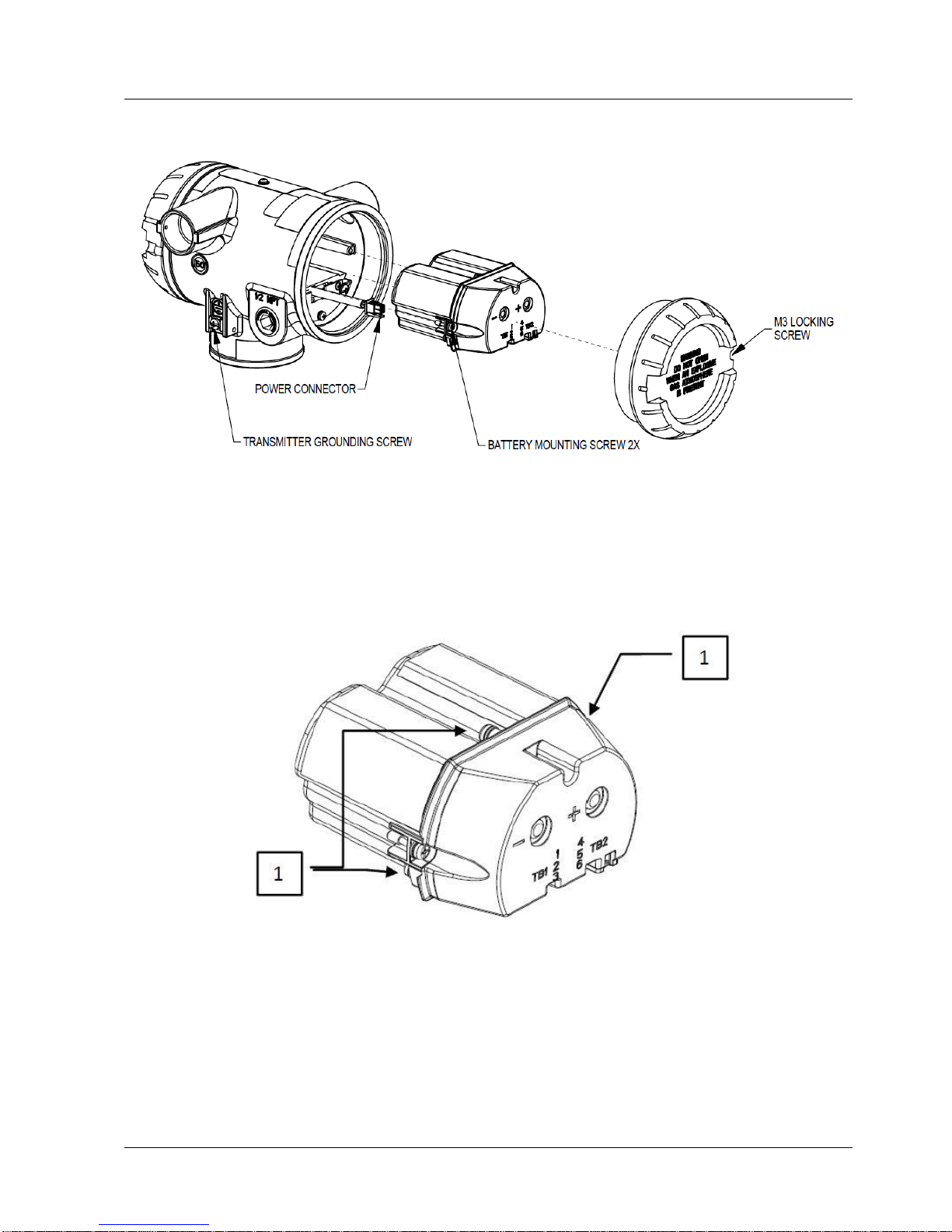
4. Start up
4.1. Battery Power Option
Revision 2 SmartLine Wireles User's Manual 39
Figure 4-1: IS Battery Pack Installation
Battery Pack
Repalcement Battery Pack (without batteries) Honeywell part number: 50047517-501
Figure 4-2: IS Battery Pack
Page 54

4. Start up
4.1. Battery Power Option
40 SmartLine Wireless User's Manual Revision 2
Battery Pack installation and replacement procedure
Tools
required
#1 Phillips Screwdriver or 1/8” Slotted Screwdriver
Torque Screwdriver
1.5 mm hex key
It is the User/Installer’s responsibility to install the SmartLine Wireless Transmitters in
accordance with national and local code requirements.
Step
Action
WARNING
DO NOT ASSEMBLE/DISASSEMBLE WHEN AN EXPLOSIVE ATMOSPHERE IS PRESENT
1. Loosen the M3 locking set screw on the battery end-cap (opposite end from
display). Unscrew and remove the end cap.
2. Using thumb and forefinger, squeeze the battery connector at top and bottom to
disengage the locking mechanism, then pull to disconnect.
3. Loosen the two-battery pack retaining screws (closest to the batteries). The screws
are captive.
4. Pull the battery pack out of the transmitter.
5. Remove top of battery pack by using a #1 Philips or 1/8” slotted screwdriver for the
screws identified as #1 in Figure 4-2
6. Remove the spent batteries and dispose of them promptly according to local
regulations of the battery manufacturer’s recommendations.
7. Install the batteries following the polarity as noted on the lid
8. Re-install top of the battery pack and tighten screws
9. Insert the Battery pack into the transmitter. Re-attach the three screws to 0.4 to 0.6
Nm (3.5 – 5.3 lb-in).
10. Reconnect the Battery Pack power connector to the transmitter
11. Ensure all wires are free of the threads to allow the cap to be re-installed
12. Honeywell recommends lubricating the end cap threads with a silicone grease such as
Dow Corning #55 or equivalent before replacing the end cap
13. Screw the cap back on and tighten the M3 locking screw
Battery Pack Test Terminals
The cap of the battery pack includes two, exposed, metal terminals marked “+” and “-“. These
terminals are for test purposes only and shall not be connected to power the transmitter. Using
an appropriate volt meter, these terminals can be used to measure the battery pack voltage (2 in
series D size lithium thionyl chloride (Li-SOCl2) batteries).
Page 55
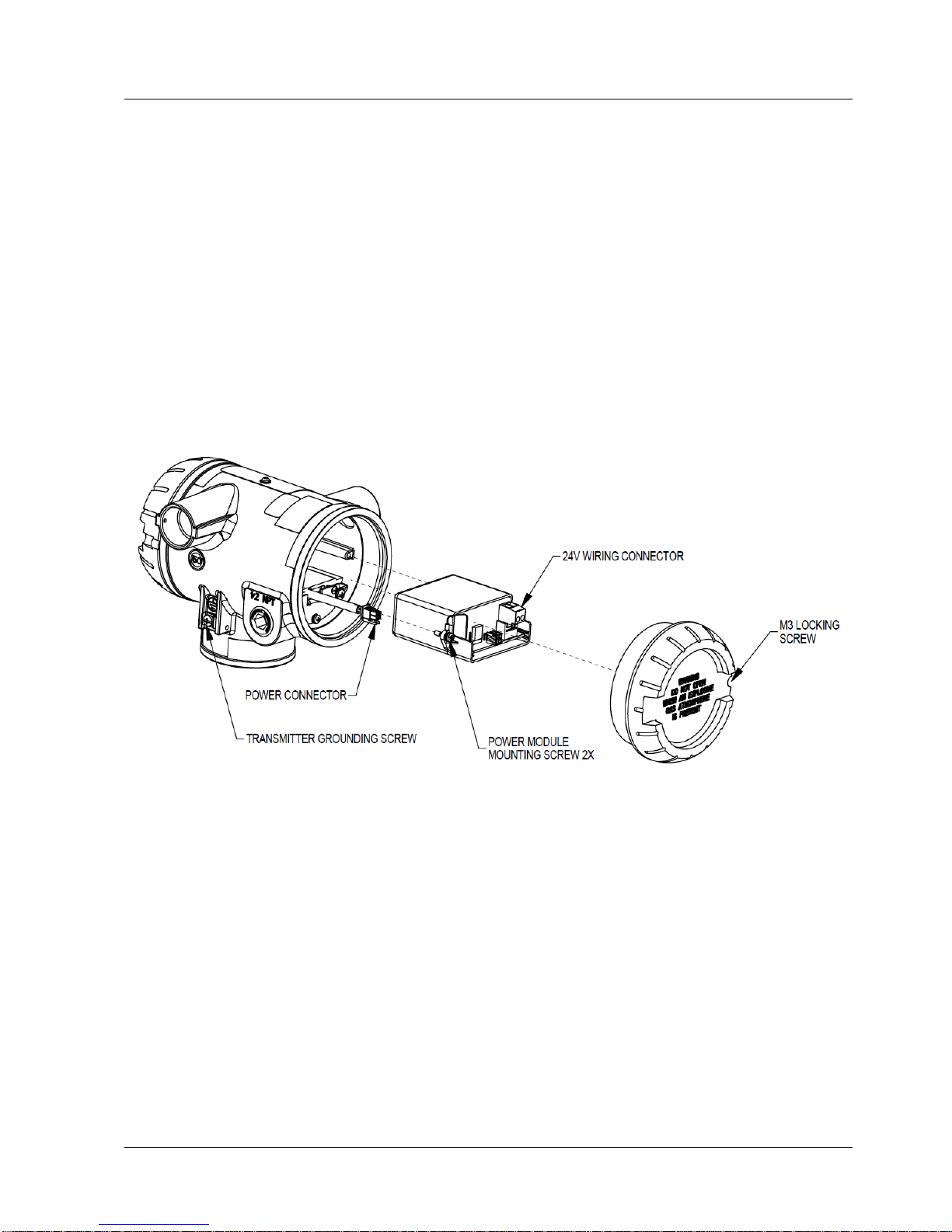
4. Start up
4.2. 24V Power Supply Option
Revision 2 SmartLine Wireles User's Manual 41
4.2 24V Power Supply Option
ELECTRICAL CONNECTION SPECIFICATIONS
The 24V power supply requires 16 Vdc to 28 Vdc, 100 mA max supply connection to the 24V wiring
connector terminals. For hazardous location installation, and intrinsic safety entity parameters, refer to
the control drawing.
1. The 24V wiring terminals accepts 26 to 12 gauge wiring. The terminals shall be torqued from 0.4
Nm to 0.5 Nm (3.5 to 4.4 lb-in).
Figure 4-3: 24V Power Supply Installation
Page 56
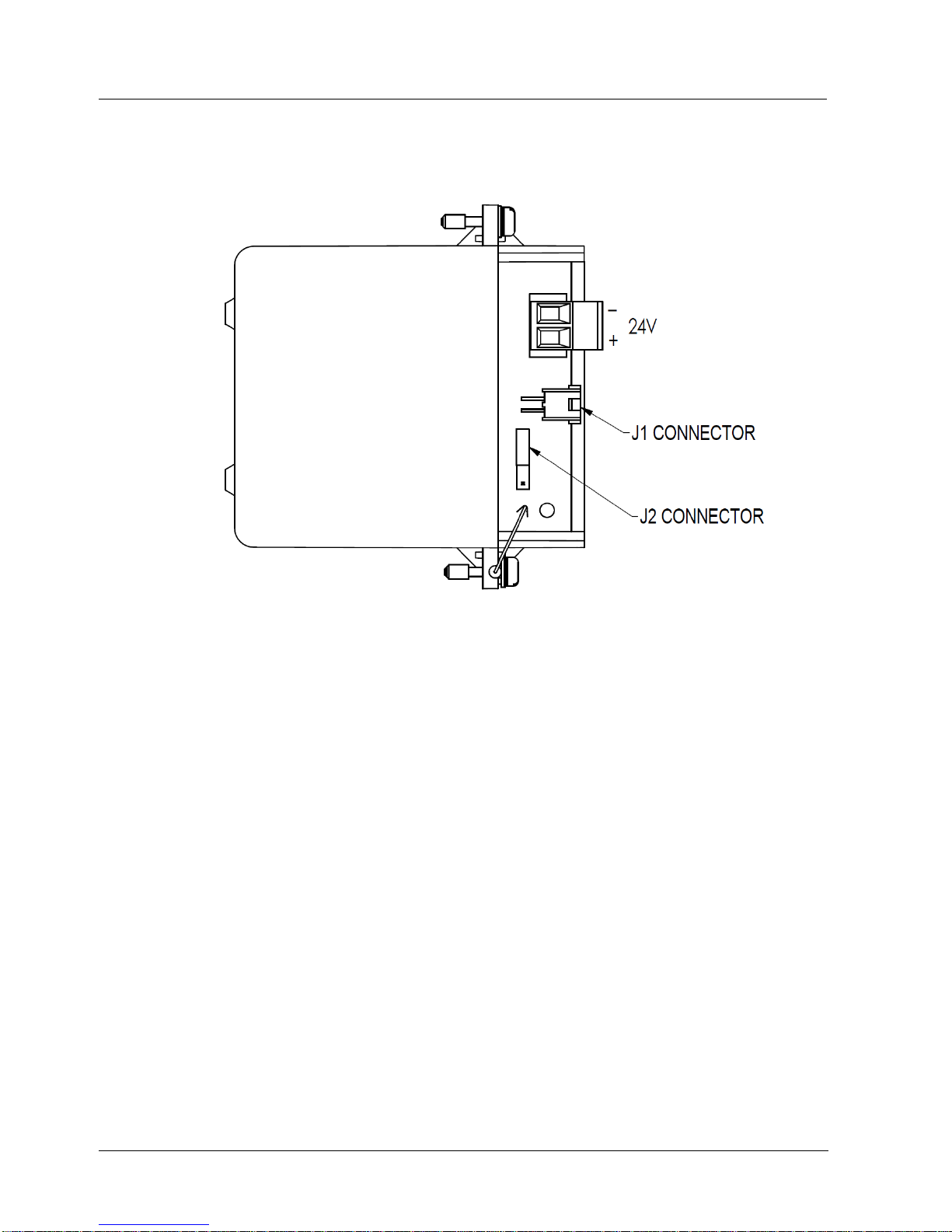
4. Start up
4.2. 24V Power Supply Option
42 SmartLine Wireless User's Manual Revision 2
24V Power Supply
Replacement 24V Power Supply Honeywell part number: 50136118-501
Figure 4-4: 24V Power Supply Module
Page 57

4. Start up
4.2. 24V Power Supply Option
Revision 2 SmartLine Wireles User's Manual 43
24V Power Supply Connection/Replacement Procedure
Tools
required
#1 Phillips Screwdriver or 1/8” Slotted Screwdriver
Torque Screwdriver
1.5 mm hex key
It is the User/Installer’s responsibility to install the SmartLine Wireless Transmitters in
accordance with national and local code requirements.
Refer to Error! Reference source not found. and Error! Reference source not found.
Step
Action
WARNING
ENSURE POWER IS OFF BEFORE OPENING COVER IN AN EXPLOSIVE ATMOSHPERE
1. Loosen the M3 locking set screw on the supply end-cap (opposite end from display).
Unscrew and remove the end cap.
2. Install a cable gland appropriate for the environment on one of the conduit entries on
the side of the enclosure. Plug the unused conduit entrance with a conduit plug
appropriate for the environment
3. Feed the power supply wires (26 to 12 gauge) through the cable gland, and insert into
the 24V terminals. The terminals tightening torque is 0.4 Nm to 0.5 Nm (3.5 to 4.4 lbin)
4. If shielded wire is used, do not terminate the shield at the transmitter. The shield
should be terminated at the power supply end.
5. If replacing the 24V power supply module, loosen the two retaining screws, ensure the
power supply connector is disconnected, and pull out the out module. Install the new
module. Reattach the screws and tighten to 0.4 – 0.6 Nm (3.5 – 5.3 lb-in).
6. Ensure the “J2” Jumper in the NON-RTD position for pressure transmitters.
7. If disconnected, reconnect the 24V Power Supply connector J1 to the transmitter
power connector.
8. Ensure all wires are free of the threads to allow the cap to be re-installed.
9. Honeywell recommends lubricating the end cap threads with a silicone grease such as
Dow Corning #55 or equivalent before replacing the end cap
10. Screw the cap back on and tighten the M3 locking screw
11. Turn on the 24V source supply
.
Page 58
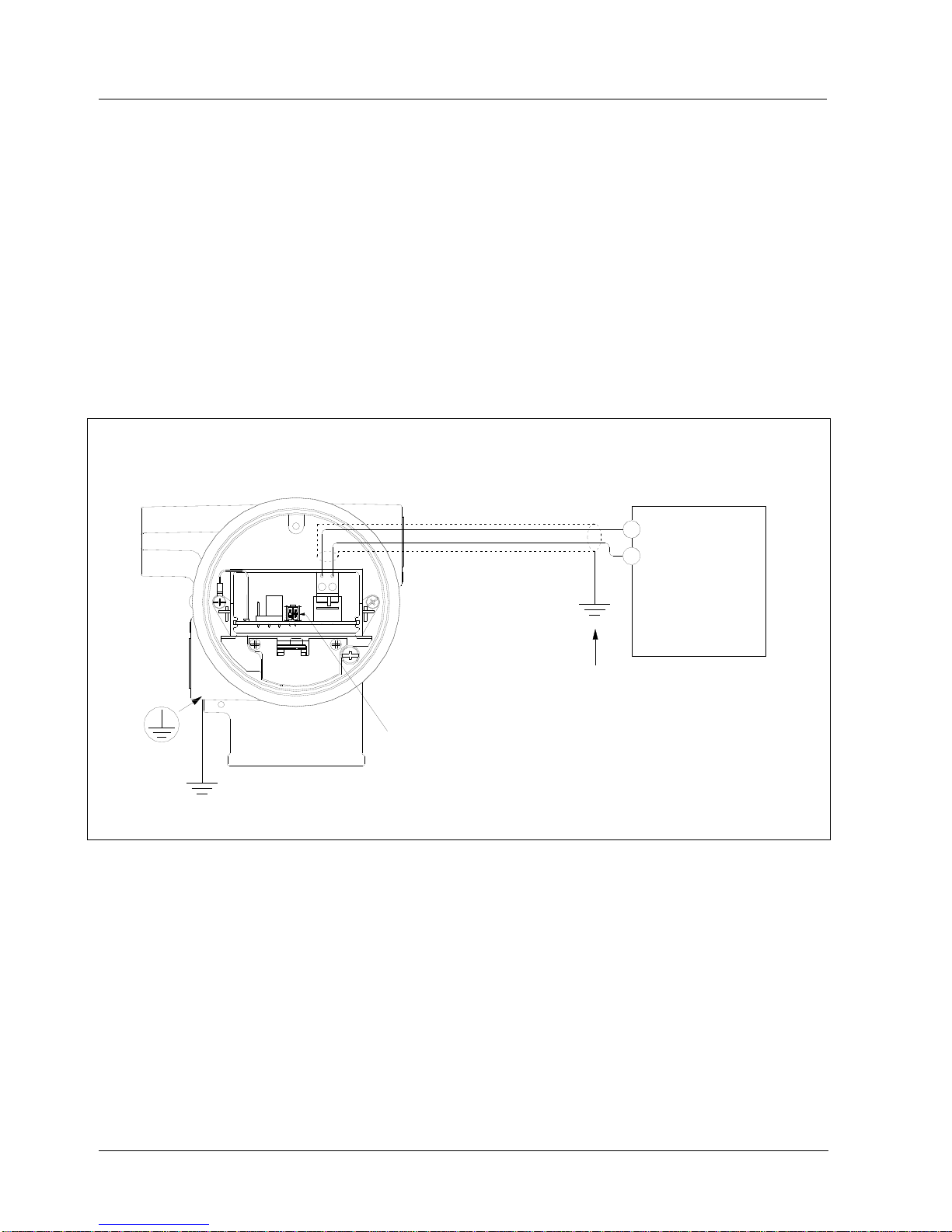
4. Start up
4.3. Grounding
44 SmartLine Wireless User's Manual Revision 2
4.3 Grounding
If the transmitter is not grounded solidly through the meterbody mounting, ground the transmitter
by connecting a wire from the Earth Ground Clamp on the side of the transmitter to Earth
Ground as short as possible. Use a size 8AWG or (8.37 mm2) bare or green covered wire for this
connection. The tightening torque for the grounding screw (shown in Figure 4-3 is 0.8 Nm to 1.0
Nm (7.1 to 8.9 lb-in).
24V dc Power Supply Option (DC) System Diagram
(Ordinary Non-Hazardous Locations)
+
-
STW TRANSMITTER WITH 24VDC POWER SUPPLY OPTION
(Antenna and Meterbody Omitted for Clarity)
GROUND SHIELD AT THIS END ONLY
+
-
THE POWER SUPPLY OUTPUT SHALL
ONLY BE CONNECTED TO THE
INTERNAL TRANSMITTER CABLE
24Vdc Supply
16.0 Vmin
28.0 Vmax
100 mA max
Figure 4-5: Power Supply 24V dc Option (DC) System Diagram
Page 59

4. Start up
4.4. Display sequence
Revision 2 SmartLine Wireles User's Manual 45
4.4 Display sequence
After power up, the transmitter will display its boot sequence which includes the firmware
revision. It will then perform a sensor (meter body) check and proceed to connecting to the
wireless network. A series of messages will be displayed depending on the network connection
status. The process variable will also be displayed. Once connected to the wireless network, an
antenna symbol (triangle) will be shown on the left hand side of the LCD along with the process
variable on the right.
4.5 Provisioning
Before the transmitter can be configured it must be provisioned with a security key so it can join
the wireless network. Use the Provisioning Device Pocket PC software to receive security keys
from the Key Server manager, then aim the Pocket PC at the transmitter and transmit a key.
Transmitters in the OneWireless Network with R240 or later release software, can be provisioned
using over-the-air provisioning.
The Wireless Device Manager (WDM) provisions the access points, and the access points that
are enabled to function as provisioning devices can then provision the transmitters. To enable
the over-the-air provisioning capability, you must first enable this feature in the OneWireless
User Interface.
For more information, please reference the One Wireless R310 Wireless Device Manager User’s
Guide (OWDOC-X254-en-310).
Page 60

4. Start up
4.6. Calibrating the transmitter
46 SmartLine Wireless User's Manual Revision 2
4.6 Calibrating the transmitter
Overview
The OneWireless User Interface must be used to calibrate the transmitter.
Calibrate zero
Calibrates the sensor to correct the input measurement due to fill fluid and transmitter position
effects once the transmitter is installed and operating under process conditions.
ATTENTION
Setting user trim points will effectively override the calibration zero. Normally
the calibration zero is only required if you do not intend to provide processspecific trim points.
Table 4-1: Calibrate zero
Step
Action
1
Apply zero input pressure for your transmitter’s pressure type as follows.
Differential: With process pressure applied, connect HP and LP inputs together using the
crossover valve on the 3-valve manifold or other equivalent method.
Gauge: Isolate the input pressure from the process and vent to the atmosphere.
Absolute: Due to the difficulty of applying absolute 0 psi, zero calibration of the AP transmitter is
not recommended.
2
In OneWireless User Interface, set the transmitter’s Software Write Protect option to Disable.
3
In OneWireless User Interface, set the transmitter’s channel to Out of Service.
4
Verify the channel is out of service (OOS) message.
If the transmitter is write protected a Read Only error will be displayed. Go to step 2.
If the channel is not out of service a WRONG MODE error will be displayed. Go to step 3.
5
Select CAL ZERO. With CAL ZERO displayed, press Enter to set the current applied pressure
to zero. If successful, the display will briefly show “ZERO SET”. If unsuccessful the display will
briefly show “ERROR”.
6
When ready, in OneWireless User Interface return the transmitter’s channel to service
Automatic and set Software Write Protect to Enable.
Page 61

4. Start up
4.6. Calibrating the transmitter
Revision 2 SmartLine Wireles User's Manual 47
Procedure for field calibration of Honeywell compound characterized SmartLine Wireless
Transmitters
This procedure applies to the following Honeywell SmartLine Wireless Transmitters
0-25 to 0-400 inH20/0-62.2 to 0-1000 mbar Compound Characterized
0-5 to 0-100 psi/0-0.34 to 0-7 bar Compound Characterized
Honeywell SmartLine Wireless Transmitters are fully characterized at the factory and have an
applied factory calibration over the range of the transmitter (URL). Field calibration is provided
to allow up to 5% adjustment over a reduced operating range providing accuracy within .075% of
the reduce range or ±0.025 + 0.05 20 psi span psi or ±0.025 + 0.05 (1.4 bar) span bar in % span.
Compound characterized pressure transmitters allow calibration at both positive and negative
relative pressure calibration points within the characterized range of the transmitters meter body.
Table 4-2: Field calibration
SmartLine
Wireless
Model
Description
Range Limits
Span Limits
Min Lower
Range
STFW128
Flange Mounted Liquid Level
Transmitter
0 to 4.0 inH2O
0 to 400 inH2O
-400 inH2O
STFW132
Flange Mounted Liquid Level
Transmitter
0 to 1.0 psi
0 to 100 psig
-100 psi
STFW924
Flange Mounted Liquid Level
Transmitter
0 to 10 inH2O
0 to 400 inH2O
-400 inH2O
STFW932
Flange Mounted Liquid Level
Transmitter
0 to 5 psi
0 to 100 psig
-100 psi
STRW12D
Remote Diaphragm Seal Pressure
Transmitter
0 to 4.0 inH2O
0 to 400 inH2O
-400 inH2O
STRW13D
Remote Diaphragm Seal Pressure
Transmitter
0 to 1.0 psi
0 to 100 psi
-100 psi
STRW93D
Remote Diaphragm Seal Pressure
Transmitter
0 to 5.0 psi
0 to 100 psig
-100 psi
Upper and Lower Calibration:
The SmartLine Wireless Transmitters provide calibration for upper and lower calibration points
as well as the option for calibration of zero. The zero calibration is independent of the upper and
lower calibration and is applied as a bias whereas upper and lower calibration adjusts the gain
and offset of the characterization. Zero calibration is available from the local interface at the
transmitter and is done with the device mounted in its operating orientation and applied “zero”
offset head pressure.
Upper and lower calibration are only available when connected to the network where access to
the upper and lower calibration points as well as access to the calibration command is available.
Upper and lower calibration requires the values for the upper and lower calibration points to be
entered and the status of the calibration operation to be verified.
Page 62

4. Start up
4.6. Calibrating the transmitter
48 SmartLine Wireless User's Manual Revision 2
Definitions:
For compound characterized meter bodies the following definition is used:
Positive applied pressure value: A positive applied pressure is an applied pressure where the
pressure at the high side of the meter body is greater than the applied pressure at the low side of
the meter body thus asserting a “positive” relative pressure between the high and low side of the
meter body.
Negative applied pressure value: A negative applied pressure is an applied pressure where the
pressure at the high side of the meter body is lower than the applied pressure at the low side of
the meter body thus asserting a “negative” relative pressure between the high and low sides of
the meter body.
One side calibration: Often only a positive calibration pressure source is available and compound
calibration is done by applying regulated pressure relative to ambient air to only one side of the
meter body with the other side of the meter body vented to ambient air. In this way a positive
calibration pressure applied to the low side of the meter body can be used to apply “negative”
relative pressure value during calibration of the lower calibration point. Both the upper and lower
calibration points can be either positive or negative values as long as the upper calibration point
is greater than the lower calibration point.
Compound Calibration Procedure:
Select the upper and lower calibration points where the transmitter is to be calibrated:
1. Select the Cal Clear command to remove any zero bias from the transmitter and return
the calibration to a gain of 1 and calibration offset zero in respect to the factory
characterization. The calibration status should return SUCCESS and the Calibration
Source will be set to NONE. This operation will set the device to a known good state.
If the calibration status does not return SUCCESS stop and call Honeywell customer
support for further assistance. Cal Clear will clear any previous user calibration including
and zero bias established using a CAL ZERO command. Factory calibration is preserved
but it is not applied.
Note: Make sure the transmitter is in the OOS (Out of Service) state prior to beginning
calibration.
2. Select the upper and lower calibration points where the transmitter is to be calibrated.
The upper and lower calibration points can be either positive or negative values as long
as the upper calibration point is greater than the lower calibration point.
3. Set the lower calibration point to the pressure value to be applied for lower calibration.
This calibration point can be either a positive or negative value as long as it is less than
the upper calibration point.
4. Set the upper calibration point to the pressure value to be applied for upper calibration.
This calibration point can be either a positive or negative value as long as it is greater
than the lower calibration point.
5. Apply the lower pressure to the meter body. When applying a negative pressure the high
side of the meter body will be at a lower pressure than the low side.
Page 63

4. Start up
4.6. Calibrating the transmitter
Revision 2 SmartLine Wireles User's Manual 49
6. Select the Cal Lower command and wait for the calibration status value to change from
NONE to SUCCESS, SUCCESS with EXCESS, or FAILURE. If the status returns
FAILURE stop and check that the value of the lower calibration point is within the range
of the meter body.
7. Apply the upper pressure to the meter body. As with the lower pressure value, when
applying a negative pressure the high side of the meter body will be at a lower pressure
than the low side.
8. Select the Cal Upper command and wait for the calibration status value to change from
NONE to SUCCESS, SUCCESS with EXCESS, or FAILURE. If the status returns
FAILURE stop and check that the value of the upper calibration point is within the range
of the meter body. If the status returns SUCCESS with EXCESS, the calibration was
applied but the adjusted characterization value is outside it’s allowed adjustment range
and the accuracy of the process value over the calibrated range is not guaranteed to be
within the specified tolerance.
Note: When applying pressure, ensure the pressure is stable to get a valid setting. Some pressure
sources can vary in pressure (bounce especially dead weight testers) and this will give false
reading.
Notes on Calibration Status:
SUCCESS: If the calibration status return SUCCESS it is indicating that the transmitter
successfully applied a gain and offset that provides a process value that is within the specified
accuracy over the calibrated range of .075% of the reduce range or ±0.025 + 0.05 20 psi span psi
or ±0.025 + 0.05 (1.4 bar) span bar in % span.
FAILURE: If the calibration status returns FAILURE it is indicating that the transmitter could
not be calibrated either due to the calibration points being beyond the range of the meter body or
the calibration span (difference between the upper and lower calibration points) is too small.
SUCCESSS with EXCESS: If the calibration status returns SUCCESS with EXCESS it is
indicating that the calibration was successful but the applied gain or offset resulting from the
calibration is deviates by more than 5% of the characterized range. This could happen if the
applied calibration pressure for either the upper or lower calibration point deviates from the
selected calibration point in a manner that will cause the adjusted gain or zero correction be
greater than 5% of the URL.
Page 64
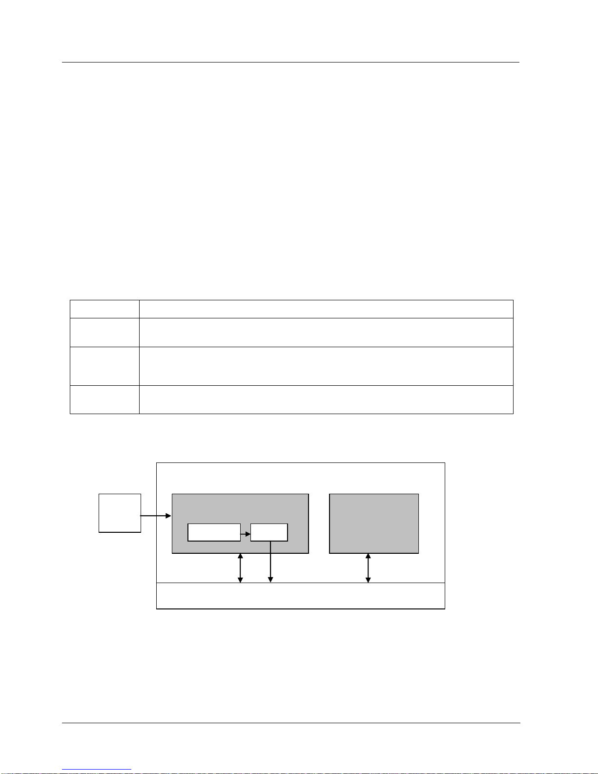
5. Function blocks
5.1. Introduction
50 SmartLine Wireless User's Manual Revision 2
5. Function blocks
5.1 Introduction
This section explains the construction and contents of the SmartLine Wireless Transmitter
Function Blocks.
5.2 Block description
Block types
Blocks are the key elements that make up the transmitter’s configuration. The blocks contain data
(block objects and parameters) which define the application, such as the inputs and outputs,
signal processing and connections to other applications. The SmartLine Wireless Transmitter
contains the following block types.
Table 5-1: Blocks
Block Type
Function
Device
Contains parameters related to the overall field device rather than a specific input or output
channel within it. A field device has exactly one device block.
AITB
Contains parameters related to a specific process input or output channel in a measurement
or actuation device. An AITB defines a measurement sensor channel for an analog process
variable represented by a floating-point value. There is one AITB per sensor.
Radio
Contains parameters related to radio communication between the transmitter and the
multimode(s).
Block diagram
Figure 5-1 shows the blocks of the SmartLine Wireless Transmitter.
Sensor Analog Input Transducer Block
(AITB)
Transmitter
Device Block
Communication Stack
Algorithm OUT
Read/
Write
Publish
Read/
Write
Sensor Analog Input Transducer Block
(AITB)
Transmitter
Device Block
Communication Stack
Algorithm OUT
Read/
Write
Publish
Read/
Write
Figure 5-1: Block Diagram
Each of these blocks contains parameters that are standard WNSIA-transmitter defined
parameters. The AITB and device blocks contain standard parameters common to all
ISA100.11a-compliant transmitters as well as model-specific parameters. The radio block
contains parameters for communication with the wireless network.
Page 65

6. Operation
6.1. Overview
Revision 2 SmartLine Wireles User's Manual 51
6. Operation
6.1 Overview
Display modes
The transmitter has the following display modes.
Test pattern. All segments appear On for 1 sec and then Off.
Connection status. Shows Status periodically and also shows an Antenna to indicate Joined
Network Status or ‘N’ to indicate Not Joined Network Status. See section 6.2.
PV display. Default mode of the transmitter displays the PV and any status messages. See
section 6.3 on page 54.
Page 66

6. Operation
6.2. Transmitter connection status
52 SmartLine Wireless User's Manual Revision 2
6.2 Transmitter connection status
Table 6-1: Transmitter connection status
Displayed
status
Definition
What to do
NO-KEY
Transmitter needs a key from the
Provisioning Device and is not transmitting.
Transmit a key to the transmitter.
See page 60.
UNJOINED
Transmitter has backed off and is in between
discovery attempts.
If Transmitter does not join the network
within five minutes, do the following:
Check that Key is correct for the network
you are trying to join.
Check that FDAP(s) in the local area are
turned on and are already a secure part
of the network.
Check if KeyServer is active.
Check the KeyServer Event Log to see if
the Transmitter is actively trying to join.
Errors in the Event Log show that the
Transmitter is trying to join but that there
are problems. Consult the OneWireless
User Interface documentation for
troubleshooting errors.
DISCOVER
Transmitter has not made a connection to a
FDAP and is in discovery (searching for a
connection to a FDAP). Transmitter will
automatically enter a power saving mode if it
cannot make a connection and will retry later.
Wait for connection. If Transmitter does not
make a connection within five minutes, see
UNJOINED in this table.
RXADVERT
The transmitter has received an
advertisement message for the ISA network
Wait for connection. If the transmitter does
not make a connection within five minutes,
see UNJOINED in this table.
FIND MAC
The transmitter is attempting to find the MAC
of the nearest FDAP
Wait for connection. If the transmitter does
not make a connection within five minutes,
see UNJOINED in this table.
WAIT MAC
The transmitter is waiting for the FDAP to
respond with its MAC address
Wait for connection. If the transmitter does
not make a connection within five minutes,
see UNJOINED in this table.
SENDSMJR
The transmitter is sending a Join Request to
the Security Manange Network Object
Wait for connection. If the transmitter does
not make a connection within five minutes,
see UNJOINED in this table.
SMJRSENT
The transmitter has sent a Join Request to
the Security Manange Network Object and is
awaiting a response
Wait for connection. If the transmitter does
not make a connection within five minutes,
see UNJOINED in this table.
SENDSMCR
The transmitter is sending a Control Request
to the Security Manager Network Object
Wait for connection. If the transmitter does
not make a connection within five minutes,
see UNJOINED in this table.
SMCRSENT
The transmitter has sent a ControlRequest to
the Security Manager Network Object and is
awaiting a response
Wait for connection. If the transmitter does
not make a connection within five minutes,
see UNJOINED in this table.
Page 67

6. Operation
6.2. Transmitter connection status
Revision 2 SmartLine Wireles User's Manual 53
SEND SCR
The transmitter is sending a Security
Confirmation Request to the Network
Wait for connection. If the transmitter does
not make a connection within five minutes,
see UNJOINED in this table.
SCR SENT
The transmitter has sent a Security
Confirmation Request to the Network and is
awaiting a response
Wait for connection. If the transmitter does
not make a connection within five minutes,
see UNJOINED in this table.
SJR SENT
The transmitter has sent a Secure Join
Request to the Network and is awaiting a
response
Wait for connection. If the transmitter does
not make a connection within five minutes,
see UNJOINED in this table.
-No MAC-
The Radio Has not been assigned a MAC
address at the factory.
Contact Honeywell Support. A new radio is
required.
JOINED
Transmitter has validated the key and has
made a secure connection with at least two
Multinodes. Transmitter should appear in
OneWireless User Interface as an
uncommissioned device.
No action required.
Page 68

6. Operation
6.3. Transmitter PV display
54 SmartLine Wireless User's Manual Revision 2
6.3 Transmitter PV display
In PV display, the following information is displayed in sequence.
Table 6-2: Transmitter PV display
Item displayed
Example
Details
PV value
4.7
Latest PV value.
PV engineering units
PSI
See Table 6-3
PV status
BAD
See Table 6-3. If PV status is not displayed,
then the PV value is good.
Device status
LOW BAT
See Table 6-3. If multiple device status
messages are in effect, they are displayed one
message per channel until all messages have
been displayed.
If no device status is displayed, then the device
status is normal.
Table 6-3: SmartLine Wireless DP units
Pressure
Description
PA
Pascal
GPA
gigapascal
MPA
megapascal
KPA
kilopascal
mPA
millipascal
uPA
micropascal
hPA
hectopascal
BAR
Bar
mBAR
millibar
TORR
Torr
ATM
Atmosphere
PSI
Pounds per square inch
PSIA
Pounds per square inch absolute
PSIG
Pounds per square inch gage
GCM2
grams per centimeter square
Page 69

6. Operation
6.3. Transmitter PV display
Revision 2 SmartLine Wireles User's Manual 55
Pressure
Description
KGCM2
Kilograms per centimeter square
INH20
Inches H2O
INH20_4C
Inches H2O referenced to 4˚C
INH20_68f
Inches H2O referenced to 68˚F
MMH20
millimeters H2O
MMH20_4C
millimeters H2O referenced to 4˚C
MMH20_68F
millimeters H2O referenced to 68˚F
FTH20
Feet H2O
FTH20_4C
Feet H2O referenced to 4˚C
FTH20_68F
Feet H2O referenced to 68˚F
INHG
Inches mercury
INHG_0C
Inches mercury referenced to 0˚C
MMGH
millimeters mercury
MMGH_0C
millimeters mercury referenced to 0˚C
For Pressure
The upper and lower calibration points indicate the upper and lower pressure value that will
correspond the upper and lower scale value respectively.
Flow = (scale EU100 – scale EU0) * sqroot(( DP – Cal Lower) / (Cal Upper – Cal Lower)) –
scale EU0 for DP > cal Lower
Flow = (scale EU100 – scale EU0) * sqroot((Cal Lower - DP) / (Cal Upper – Cal Lower)) – scale
EU0 for DP < -cal Lower
Flow = 0 for DP < abs ( cal lower)
Where scale EU100 and scale EU0 are in flow units and Cal Upper and Cal Lower are in
pressure units.
The square root function is automatically employed for conversion from pressure to flow scale
units. Calibration units are always in pressure units.
Page 70

6. Operation
6.3. Transmitter PV display
56 SmartLine Wireless User's Manual Revision 2
Table 6-4: SmartLine Wireless Flow units
FLOW
Description
CMPS
cubic meters per second
CMPM
cubic meters per minute
CMPH
cubic meters per hour
CMPD
cubic meters per day
LPS
liters per second
LPM
liters per minute
LPH
liters per hour
LPD
liters per day
MLPD
million liters per day
CFPS
cubic feet per second
CFPM
cubic feet per minute
CFPH
cubic feet per hour
CFPD
cubic feet per day
SCFPM
standard cubic meters per second
SCFPH
standard cubic meters per minute
USGPS
US gallons per second
USGPM
US gallons per minute
USGPH
US gallons per hour
USGPD
US gallons per day
MUSGPD
million US gallons per day
IGPS
Imperial gallons per second
IGPM
Imperial gallons per minute
IGPH
Imperial gallons per hour
IGPD
Imperial gallons per day
Page 71

6. Operation
6.3. Transmitter PV display
Revision 2 SmartLine Wireles User's Manual 57
For Flow:
1. Select the upper and lower scale values in flow units.
2. Set the Pressure Scale 100% EU value to the pressure that will be asserted when the flow
is to be the upper scale value.
3. Set the Pressure Scale 0% EU value to the pressure that will be asserted when the flow is
to be the lower scale value.
PV status
PV Status is indicated by the Second Left-most Character on the display when showing the PV
Value. Blank indicates good/normal status. ‘B’ Indicated Bad Status. ‘U’ indicates uncertain
status and ‘F’ indicates Failure Status.
Table 6-5: PV Status
PV status
Cause - Action
(blank)
PV is normal – no action required
‘B’
Possible calibration error – Clear calibration
AITB cannot execute due to internal firmware state – Attempt cold restart of
device.
AITB cannot execute due to hardware fault – Replace sensor board
Sensor failure – Check Connection between Sensor board and meter body.
Meter body Characterization Data is Bad – Replace meter body
Meter body A/D Failure – Replace meter body
Meter body Sensor Fail – Replace meter body
Configuration is bad – Check possible units and range settings for input type
and correct AITB configuration.
Hardware fault detected - Replace sensor board
‘U’
Warning: Calibration (zero or trim) is causing excessive adjustment to
characterization value.
Warning: Input inaccurate due to uncertain input data integrity.
Warning: Input inaccurate due to input conversion limitations or resolution.
Warning: Input outside of characterized range. Value is estimated.
‘F’
Sensor Failure has occurred or the transmitter was unable to communicate
with the sensor.
Check the connection between the Sensor and the Main Board of the
transmitter.
Contact Honeywell Support if the problem persists.
Page 72

6. Operation
6.3. Transmitter PV display
58 SmartLine Wireless User's Manual Revision 2
Table 6-6: Device status
Transmitter display
OneWireless User
Interface display
Definition
What to do
OoS
OOS
All channels are out of
service.
Restore mode to Auto in
OneWireless User Interface.
SNSR ERR
Sensor Error
Sensor can not access
meter body A/D
converter.
Check connection between
sensor module and meter
body. If still doesn't work,
replace sensor. See page 70.
OVR TEMP
Over Temperature
The meter body has
exceeded the
maximum temperature
as defined by the meter
body characterization
data.
Determine cause excessive
temperature.
OVR LOAD
Over Load
The applied pressure
has exceeded the limit
defined by the meter
body characterization
data.
Determine cause of over
pressure.
‘U’ Status
Calibration Error
Calibration Data Invalid
or could not be read.
Use Cal Clear, or User
Calibrate.
LOW BAT
Low Battery
Battery Voltage
Critically Low
Replace batteries as soon as
possible. See page 71.
NO RADIO
Radio Interprocessor
Comm Error
Radio Board is not
accessible.
Restart both the radio and
sensor. If condition persists,
replace sensor module. See
page 70.
The following status messages have multiple meanings. Refer to OneWireless UI Device Status for exact cause.
‘F’ Status
Input Failure
Input Error
Possible meter body sensor
failure.
‘F’ Status
NVM Fault*
Startup diagnostics
detected defect in
Sensor Non-Volatile
Memory
Replace sensor module. See
page 70.
‘F’ Status
Program Memory
Fault*
Startup diagnostics
detected defect in
Sensor Read Only
Memory
Replace sensor module. See
page 70.
‘F’ Status
RAM Fault*
Startup diagnostics
detected defect in
Processor Random
Access Memory
Replace sensor module. See
page 70.
The following statuses are displayed only in OneWireless UI Device Status.
Page 73

6. Operation
6.3. Transmitter PV display
Revision 2 SmartLine Wireles User's Manual 59
Transmitter display
OneWireless User
Interface display
Definition
What to do
‘U’ Status
Excess Zero
Calibration
The selected zero
offset or the lower
calibration trim point is
beyond 5% of the lower
end of the
characterized range of
the device.
Clear Calibration
‘U’ Status
Excess Span
Calibration
The calibrated upper
and lower trim has
produced a span that is
greater than 5% of the
characterized span of
the transmitter.
Clear Calibration
Or
Set Factory Calibration
Or
Check the applied trim points
and re-attempt lower and
upper (trim) calibration.
‘U’ Status
Excess Calibrated
Range
The selected
calibration points used
for upper and lower
trim are outside the
characterized range of
the transmitter.
Check that the upper and
lower trim points are both
within the characterized range
of the transmitter and reattempt upper and lower (trim)
calibration.
blank
Calibration Cleared
Indicates that both the
upper and lower trim
points as well as the
zero offset has been
cleared. The calibration
source is none.
Calibration the zero offset
Or
Calibrate using the lower and
upper trim points.
Page 74
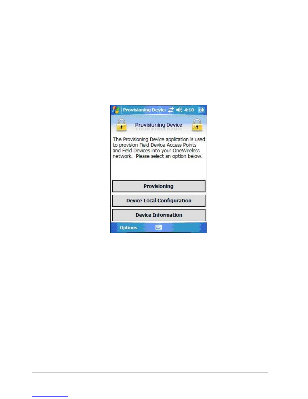
6. Operation
6.4. Provisioning Device menus
60 SmartLine Wireless User's Manual Revision 2
6.4 Provisioning Device menus
Overview
Hold the Provisioning Device no more than 6” (15 cm) from the transmitter and aim the infrared
beam at the transmitter display while tapping on the screen command or button.
Main menu
The main menu is shown below. Details start on the next page.
Figure 6-1: Main menu
Security and Node Deployment
Use this to:
receive new security keys,
transmit security keys for connecting the transmitter (or other nodes) to the OneWireless
network,
clear all security keys from the Provisioning Device,
clear the transmitter’s key and reset its configuration to factory defaults (such as for
deprovisioning).
Page 75
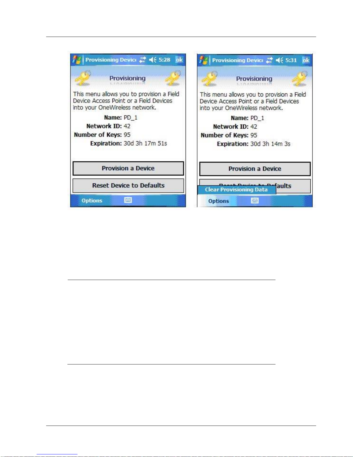
6. Operation
6.4. Provisioning Device menus
Revision 2 SmartLine Wireles User's Manual 61
Figure 6-2: Security and Node Deployment
To connect your transmitter to the OneWireless network perform the following steps.
Step
Action
1
If the Provisioning Device contains no keys, obtain new security keys from
the WDM Provisioning tab
2
When the Provisioning Device has valid unexpired keys, aim it at the
transmitter and transmit a key to the transmitter. The transmitter will validate
the key and then use it to make a connection to the OneWireless network.
The Transmitter may continue to show the diagnostic message “NO KEY” for
a brief time while it validates the key before showing the “DISCOVER”
message.
To verify your transmitter has been provisioned, see the Connection prompt
on the Read Device Information screen Figure 6-3
Page 76
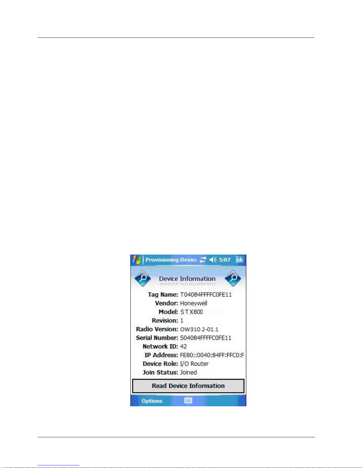
6. Operation
6.4. Provisioning Device menus
62 SmartLine Wireless User's Manual Revision 2
De-provisioning
To de-provision the transmitter from the network and reset all settings to their default factory
values, select Reset Device to Defaults. To simply remove the device from the network select the
transmitter in the WDM and click Delete. This will remove the device from the network and you
will have to manually accept it back onto the network via the WDM interface if you want it to rejoin the same network. This will preserve the settings and Key data etc. If the device is to be
moved to a different ISA100 Network then the only option is to Reset Device to Defaults, and
provision it for the new network. In this case any custom settings will have to be re-applied once
the transmitter is on the new network.
To reset to defaults, perform the following steps:
Select Provisioning Data (under Advanced Options) when:
The Provisioning Device has keys from one system, but you are using provision device on
another system, or
you want to clear all keys so that you cannot deploy any more keys without going to the
Wireless System Gateway user interface and getting more.
For more details on keys, refer to the One Wireless documents in References
Read Device Information
Use this to read the transmitter’s information shown in Figure 6-3.
Similar to quick view parameters on the transmitter display.
Figure 6-3: Read Device Information
Page 77

6. Operation
6.4. Provisioning Device menus
Revision 2 SmartLine Wireles User's Manual 63
Table 6-7: Read Device Information
Item
Description
Tag Name:
The name given to this transmitter
Vendor:
Manufacturer of device
Model:
Description of device
Revision:
Software revision of sensor firmware
Radio Version:
Software revision of radio firmware
Serial Number:
Transmitter serial number. This is the WBSN on the
transmitter’s nameplate. Do not confuse this with the other
nameplate item marked “Serial.”
Network ID
Network Address of the device in hexadecimal.
IP Address:
IP Address of radio
Device Role:
Function of the device in the wireless network.
No Routing – Device functions only as a transmitter
I/O Router – Device functions both as a transmitter and as a
field router
Join Status:
The first line displays one of the following connection states.
No Security Key – No security key has been deployed to
the device or multinode. The user must give a security key
to the device or multinode before it will join the wireless
sensor network.
Not Joined – A security key exists in the device or
multinode, but no connection has been formed. The device
or multinode is waiting to form a connection and will
automatically retry shortly. Users may transmit a new
security key in order to force the device or multinode to
immediately retry to form a connection.
Discover – The device is attempting to form a connection to
the wireless sensor network. The device is discovering
multinodes and, if a multinode is found, will transition to the
securing state.
Joined – A secure connection is formed with the network.
The second line contains detailed state information useful for
problem reporting.
Page 78
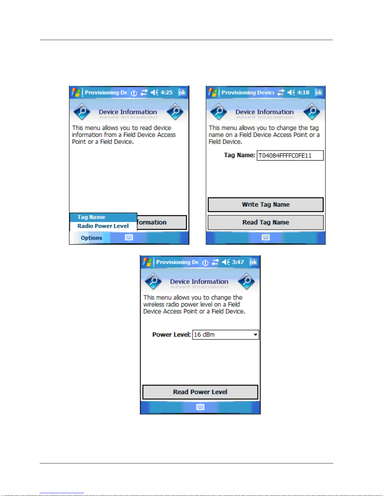
6. Operation
6.4. Provisioning Device menus
64 SmartLine Wireless User's Manual Revision 2
Advanced Options
Advanced options are non-typical configuration commands.
Figure 6-4: Advanced Options
Page 79

6. Operation
6.4. Provisioning Device menus
Revision 2 SmartLine Wireles User's Manual 65
Table 6-8: Advanced Options
Item
Description
Read Power Level
Reads the transmission power level of the transmitter radio.
Read Tag Name
Reads the transmitter’s tag name
Write Tag Name
Write the transmitter’s tag name with the entered text, maximum 16 characters
Page 80

7. Maintenance/Repair
7.1. Introduction
66 SmartLine Wireless User's Manual Revision 2
7. Maintenance/Repair
7.1 Introduction
This section provides information about preventive maintenance routines and replacing damaged
parts. The topics covered in this section are:
Preventive maintenance of the meter body barrier diaphragms and process piping to the
transmitter.
Replacement of damaged parts such as the transmitter display/sensor and batteries.
7.2 Preventive maintenance
The SmartLine Wireless Transmitter itself does not require any specific maintenance routine at
regularly scheduled intervals. However, you should consider carrying out these typical inspection
and maintenance routines on a schedule that is dictated by the characteristics of the process
medium being measured and whether blow-down facilities or purge systems are being used.
Check piping for leaks.
Clear the piping of sediment or other foreign matter.
Clean the transmitter’s pressure chambers including the barrier diaphragms.
7.3 Inspecting and cleaning barrier diaphragms
Depending on the characteristics of the process medium being measured, sediment or other
foreign particles may collect in the process head cavity/chamber and cause faulty measurement.
In addition, the barrier diaphragm or diaphragms in the transmitter’s meter body may become
coated with a residue from the process medium. The latter is also true for external diaphragms on
flange mount and remote seal type transmitters.
In most cases, you can readily remove the process head or heads from the transmitter’s meter
body to clean the process head cavity and inspect the barrier diaphragm or diaphragms. For
flange mount and remote seal diaphragms, you may only need to run a purge line in the tank to
rinse off the face of the diaphragm.
The procedure in Table 7-1 outlines the general steps for inspecting and cleaning barrier
diaphragms. You may have to modify the steps to meet your particular process or transmitter
model requirements. Figure 7-1 shows an exploded view of a DP transmitter’s meter body for
reference.
Tools required
5/8” Wrench or Socket for 7/16” Dia. Hex Bolt
3/4” Wrench or Socket for 7/16” Hex Nut
Calibrated torque wrench. For the most accurate performance, select a torque wrench with
which the applied torque value is near the middle of the tool’s torque range. For example, if
applying 68 Nm (50 lb-ft), select a torque wrench with range of 7 Nm to 136 Nm (5 to 100
lb-ft).
Page 81
7. Maintenance/Repair
7.3. Inspecting and cleaning barrier diaphragms
Revision 2 SmartLine Wireles User's Manual 67
WARNING
Risk of death or serious injury by explosion. Do not open transmitter
enclosure when an explosive gas atmosphere is present.
Procedure
Table 7-1: Inspecting and Cleaning Barrier Diaphragms
Step
Action
1
Close all valves and isolate transmitter from process. Open vent in process head to drain fluid
from transmitter’s meter body, if required.
ATTENTION
We recommend that you remove the transmitter from service and move it to a clean area
before taking it apart.
WARNING
Risk of death or serious injury by explosion. Do not open transmitter enclosure when an
explosive gas atmosphere is present.
2
Remove nuts from bolts that hold process head or heads to meter body. Remove process
heads and bolts. See Figure 7-1
3
Remove gasket and clean interior of process head using soft bristle brush and suitable solvent.
CAUTION
Diaphragm surface is fragile. Be very gentle, do not damage.
4
Inspect barrier diaphragm for any signs of deterioration or corrosion. Look for possible residue
and clean if necessary.
If diaphragm is dented, has distorted convolutions or radial wrinkles, performance may be
affected. Contact Honeywell for assistance.
5
Replace process head gasket.
ATTENTION
We recommend that you install a new gasket whenever a process head is removed for
cleaning.
For process heads of a GP or AP transmitter with dual-head design, see illustration for
differential pressure transmitters in Figure 7-1.
6
Coat threads on process head bolts with anti-seize compound such as “Neverseize” or
equivalent.
7
Replace process head or heads and bolts. Finger tighten nuts.
8
Use a torque wrench to gradually tighten nuts to torque rating shown in Table 7-2, and in
sequence shown in Figure 7-1. Tighten head bolts in stages of 1/3 full torque, 2/3 full torque,
and then full torque.
9
Return transmitter to service.
Page 82
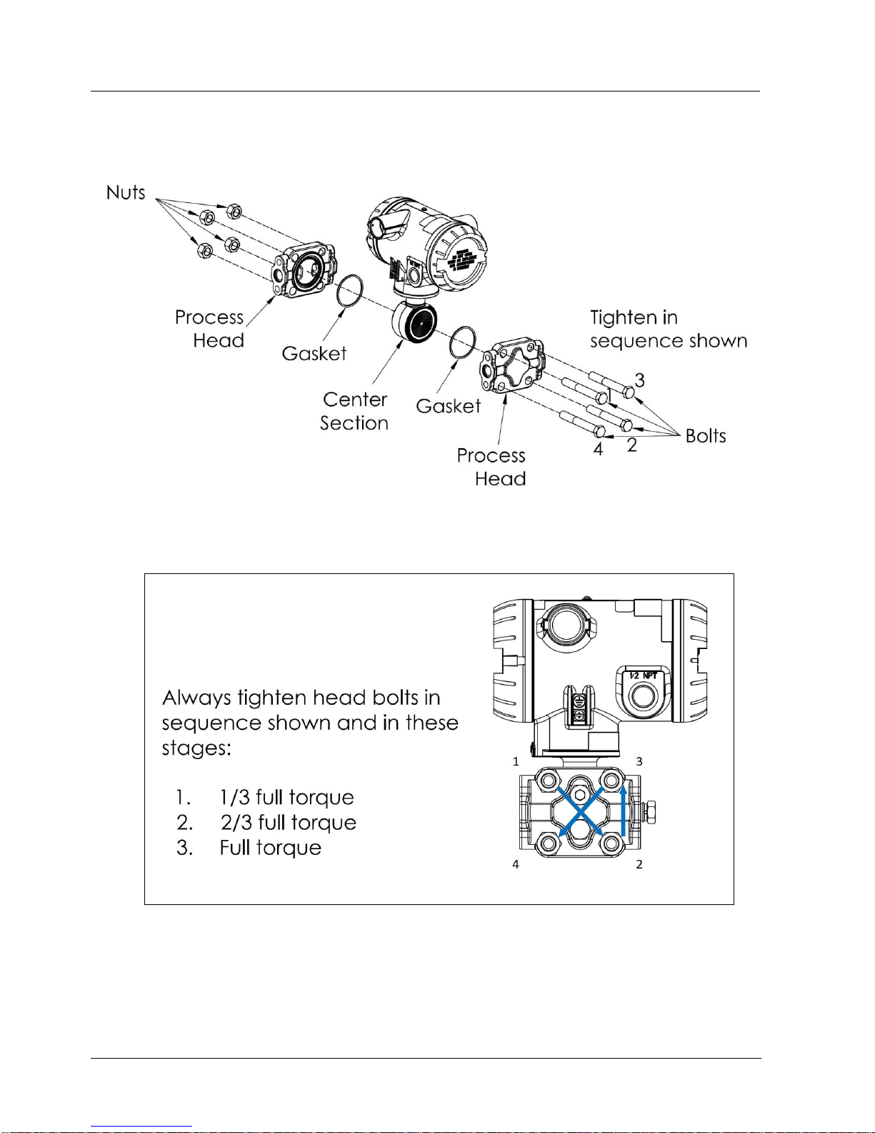
7. Maintenance/Repair
7.3. Inspecting and cleaning barrier diaphragms
68 SmartLine Wireless User's Manual Revision 2
Figure 7-1: Assembly of DP Transmitter Process Heads
Figure 7-2: STW Standard Transmitter - Head Bolt Tightening Sequence
Page 83

7. Maintenance/Repair
7.3. Inspecting and cleaning barrier diaphragms
Revision 2 SmartLine Wireles User's Manual 69
Torque ratings
Table 7-2: Head Bolt Torque Values
Bolting Type
B7M
bolting
Table III
B7 option
Bolt
51452557004
Nut
51452559003
PTFE
Coated
B7M
bolting Y
special
option
Bolt
51452557007
Nut
51452559007
MONEL
K500
bolting Y
special
option
Bolt
51452557005
Nut
51452559005
25%
Chromium
super
duplex
bolting Y
special
option
Bolt
51452557006
Nut
51452559006
316
Satiless
Steel
bolting
table III
SS option
Bolt
51452557003
Nut
51452559003
Bolt
51452557004
NACE CR
bolting
Table III
CR option
Bolt
51452557002
Nut
51452559002
All Grade
660 class
D bolting
Y special
option
Bolt
51452557001
Nut
51452559008
Carbon
Steel
bolting
standard
option
Bolt
51452557001
Nut
51452559001
All Grade
660 class D
bolting Y
special 6
KPSI option
Bolt
51452557202
Nut
51452559008
50049713XXXX
Except XXX5
all transmitters
except draft
range
48,8 Nm +/- 2,4 Nm (36.0 lb-ft +/- 1.8 lb-ft)
56,9 Nm +/- 2,8 Nm
(42.0 lb-ft +/- 2.1 lb-ft)
67,8 Nm +/- 3,4 Nm
(50.0 lb-ft +/- 2.5 lb-ft)
50049713XXX5
draft range
transmitters
only
20,3 Nm +/- 1,0 Nm (15.0 lb-ft +/- 0.8 lb-ft)
Page 84
7. Maintenance/Repair
7.4. Replacing Electronics Module
70 SmartLine Wireless User's Manual Revision 2
7.4 Replacing Electronics Module
Tools required
#1 Phillips Screwdriver or 1/8” Slotted Screwdriver
Torque Screwdriver
1.5 mm hex key
Procedure
WARNING
Risk of death or serious injury by explosion. Do not open transmitter
enclosure when an explosive gas atmosphere is present.
CAUTION
Take precautions against electrostatic discharge to prevent damaging the
sensor module.
Table 7-3: Electronics module replacement
Step
Action
1
Honeywell recommends that the transmitter be removed from service and moved to a clean
area before servicing.
2
Loosen the M3 locking set screw on the display end-cap. See item 1 in Figure 7-3. Unscrew
and remove the end cap.
3
Loosen the two screws on the electronics module. See items 2 in Figure 7-3
4
Disconnect each connector on the electronics module. See items 3 in Figure 7-3
5
Install new electronics module. Be sure to orient the module in the proper viewing orientation
before tightening two sensor compartment screws.
Reverse steps 1-4.
Torque screws to 0,4 – 0,6 Nm (3.5 – 5.3 lb-in).
Honeywell recommends lubricating the end cap O-ring with a Silicone Grease such as Dow
Corning #55 or equivalent before replacing the end cap.
Return transmitter to service.
Page 85
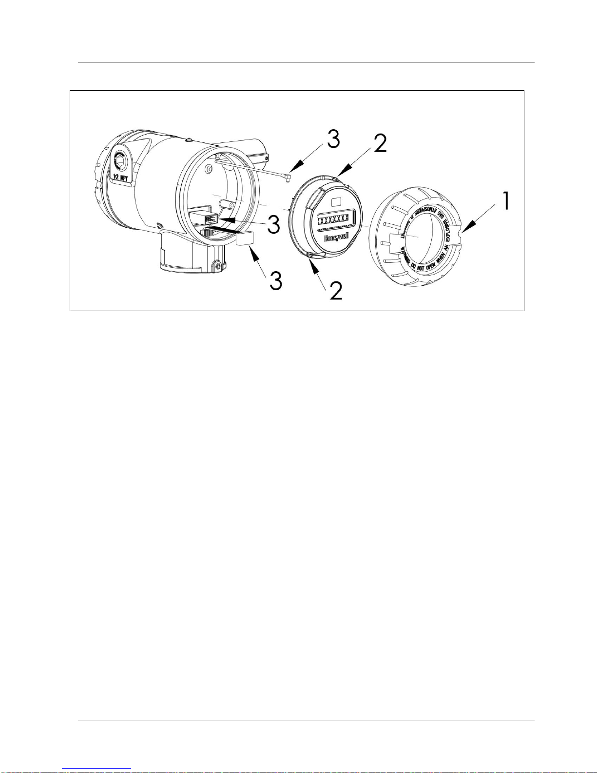
7. Maintenance/Repair
7.5. Replacing batteries
Revision 2 SmartLine Wireles User's Manual 71
Figure 7-3: Sensor module removal and replacement
7.5 Replacing batteries
When to replace
When the transmitter displays a LOW BAT message you have 2-4 weeks to replace both
batteries before they reduce in performance. When batteries are removed or expired, all
transmitter data is retained in the transmitter’s non-volatile memory.
See section 4.1 for battery replacement procedure.
7.6 Replacing 24V external power module
When to replace
If the 24V power source should be replaced if the transmitter doesn’t power up or the output
voltage of the 24V supply is less than 7.5V.
See section 4.2 for 24V power supply module replacement procedure.
Page 86
7. Maintenance/Repair
7.7. Replacing antenna
72 SmartLine Wireless User's Manual Revision 2
7.7 Replacing antenna
Tools required
#1 Phillips Screwdriver or 1/8” Slotted Screwdriver
Torque Screwdriver
1.5 mm hex key
Procedure
ATTENTION
You must replace your antenna with the same type, that is, elbow, straight, or
remote. Changing to a different antenna type is not permitted by approval
agencies.
CAUTION
Take precautions against electrostatic discharge to prevent damaging the
sensor module.
WARNING
POTENTIAL ELECTROSTATIC CHARGING HAZARD
The integrally mounted antenna shroud is made of Teflon® and has a surface
resistance greater than 1G ohm per square. When the SmartLine Wireless
transmitter is installed in potentially hazardous locations care should be taken
not to electrostatically charge the surface of the antenna shroud by rubbing
the surface with a cloth, or cleaning the surface with a solvent. If
electrostatically charged, discharge of the antenna shroud to a person or a
tool could possibly ignite a surrounding hazardous atmosphere.
Page 87

7. Maintenance/Repair
7.7. Replacing antenna
Revision 2 SmartLine Wireles User's Manual 73
Antenna replacement procedure
Step
Action
1
Honeywell recommends that the transmitter be removed from service and moved to a clean
area before servicing.
2
Loosen the M3 locking set screw on the display end-cap. See item 1 in Figure 7-4. Unscrew
and remove the front end cap.
3
Loosen the two screws on the sensor module. See items 2 in Figure 7-4
4
Remove the sensor module from the transmitter body and disconnect the antenna connector
from CN2 connector on the sensor module. See item 3 in Figure 7-4
5
Loosen the locking set screw at the antenna base. Unscrew the antenna from the transmitter.
Remove the antenna and its connector from the transmitter. See Figure 7-4
6
Feed the new antenna’s connector through the antenna hole to the front of the transmitter. Do
not connect to sensor module yet. Lubricate O-ring with a Silicone Grease such as Dow
Corning #55 Screw new antenna into transmitter body until finger-tight, then back off 180
degrees to permit adjustment later.
7
Attach antenna connector to CN2 connector on sensor module. See item 3 in Figure 7-4.
8
Insert sensor module. Orient in the proper viewing orientation before tightening two sensor
compartment screws. See items 2 in Figure 7-4. Torque screws to 0,4 – 0,6 Nm (3.5 – 5.3 lbin).
9
Replace the front end cap. Honeywell recommends lubricating the front end cap O-ring with a
Silicone Grease such as Dow Corning #55 or equivalent before replacing the end cap.
10
Adjust antenna for best reception. Don’t rotate antenna more than 180 degrees either direction
or you could twist and break the antenna wiring inside. Tighten the antenna locking set screw.
Page 88
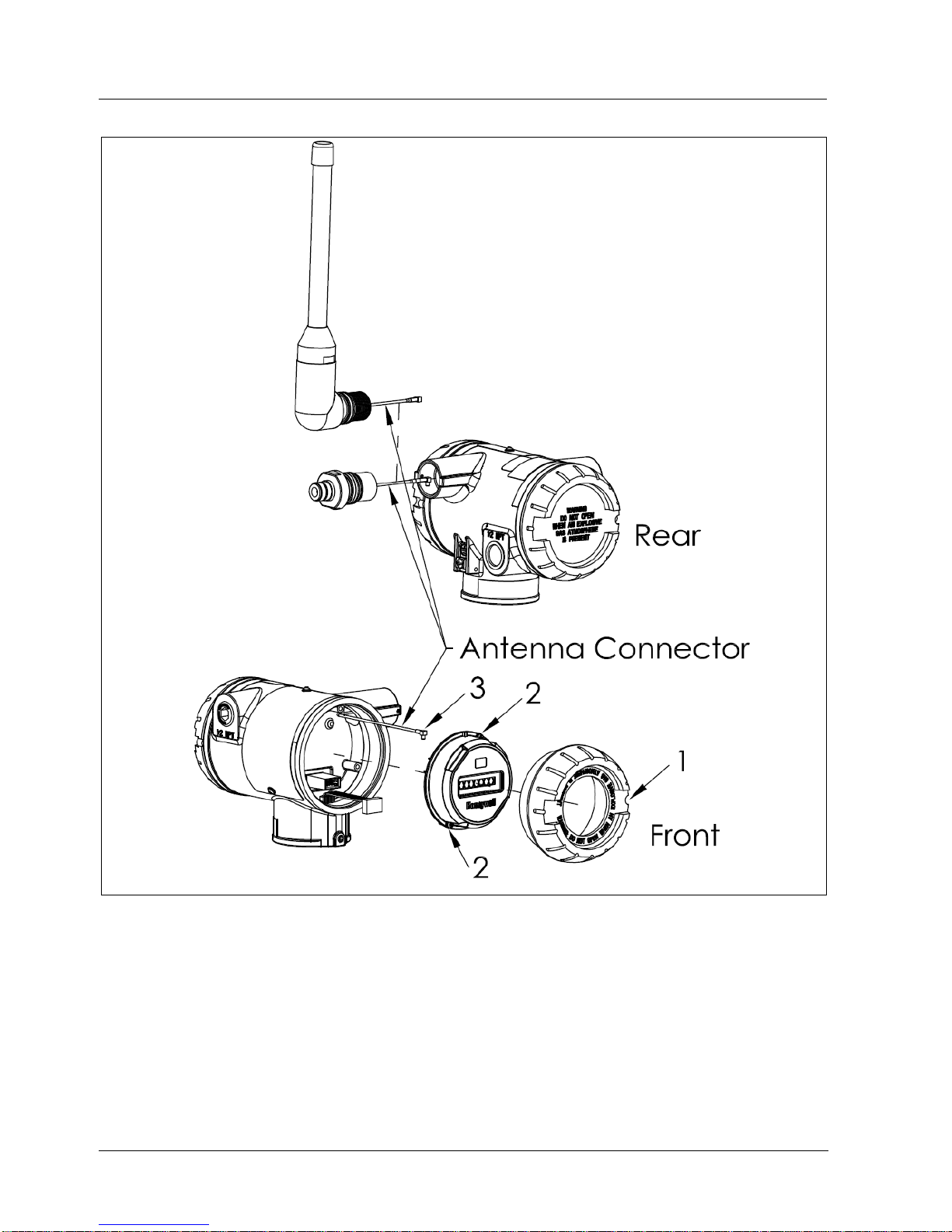
7. Maintenance/Repair
7.7. Replacing antenna
74 SmartLine Wireless User's Manual Revision 2
Figure 7-4: Antenna replacement
Page 89

8. Parts
7.8. Transmitter body
Revision 2 SmartLine Wireles User's Manual 75
8. Parts
Individually saleable parts for the various transmitter models are listed in this section. Some parts
are illustrated for identification. Parts are identified and listed in the corresponding tables as
follows:
Individually saleable parts are indicated in each figure by key number callout.
Parts that are supplied in kits are indicated in each illustration by key number callout
with the letter K prefix.
Note that the meter body replacement parts and mounting brackets for the SmartLine wireless
pressure transmitters are the same as and interchangeable with the STW700/800 series of
pressure transmitters, for like models.
7.8 Transmitter body
Table 8-1: Transmitter Body Parts
Part number
Qty
Description
50136119-501
1
ELECTRONICS MODULE ASSEMBLY aka SENSOR MODULE for Pressure
ISA100.11a
50016190-507
1
CAP ASSEMBLY, BATTERY, ALUMINUM, BLUE, POLYESTER POWDER COAT
50016190-508
1
CAP ASSEMBLY, BATTERY, ALUMINUM, BLUE, EPOXY-POLYESTER POWDER
COAT
50015623-504
1
CAP ASSEMBLY, LCD, ALUMINUM, BLUE, POLYESTER POWDER COAT
50015623-505
1
CAP ASSEMBLY, LCD, ALUMINUM, BLUE, EPOXY-POLYESTER POWDER COAT
50026127-503
1
CAP ASSEMBLY, BATTERY, STAINLESS STEEL
50026009-502
1
CAP ASSEMBLY, LCD, STAINLESS STEEL
50031715-503
1
ANTENNA ASSEMBLY, 4 dBi INTEGRAL, ALUMINUM, POLYESTER POWDER COAT
50031715-504
1
ANTENNA ASSEMBLY, 4 dBi INTEGRAL, ALUMINUM, EPOXY-POLYESTER
POWDER COAT
50031715-505
1
ANTENNA ASSEMBLY, 4 dBi INTEGRAL, STAINLESS STEEL
50018414-001
1
REMOTE OMNI-DIRECTIONAL ANTENNA, 8 dBi
50018415-001
1
REMOTE DIRECTIONAL ANTENNA, 14 dBi
50028364-503
1
ANTENNA ADAPTER ASSEMBLY, REMOTE, TYPE N, ALUMINUM, POLYESTER
50028364-504
1
ANTENNA ADAPTER ASSEMBLY, REMOTE, TYPE N, ALUMINUM, EPOXYPOLYESTER
50028364-505
1
ANTENNA ADAPTER ASSEMBLY, REMOTE, TYPE N, STAINLESS STEEL
50018278-001
1
COAX CABLE ASSY, 1.0M ( 3.3 Ft) LONG, N-MALE - N-MALE
50018278-002
1
COAX CABLE ASSY, 3.0M (10.0 Ft) LONG, N-MALE - N-MALE
50018278-003
1
COAX CABLE ASSY, 10.0M (33.0 Ft) LONG, N-MALE - N-MALE
50018279-090
1
LIGHTNING SURGE ARRESTOR
50047517-501
1
I.S. BATTERY PACK HOUSING ASSEMBLY
50136118-501
1
24V EXTERNAL POWER MODULE
50026010-001
2
3.6V LITHIUM THIONYL CHLORIDE (Li-SOCI2) BATTERY
50026010-002
4
3.6V LITHIUM THIONYL CHLORIDE (Li-SOCI2) BATTERY
50026010-003
10
3.6V LITHIUM THIONYL CHLORIDE (Li-SOCI2) BATTERY
Page 90
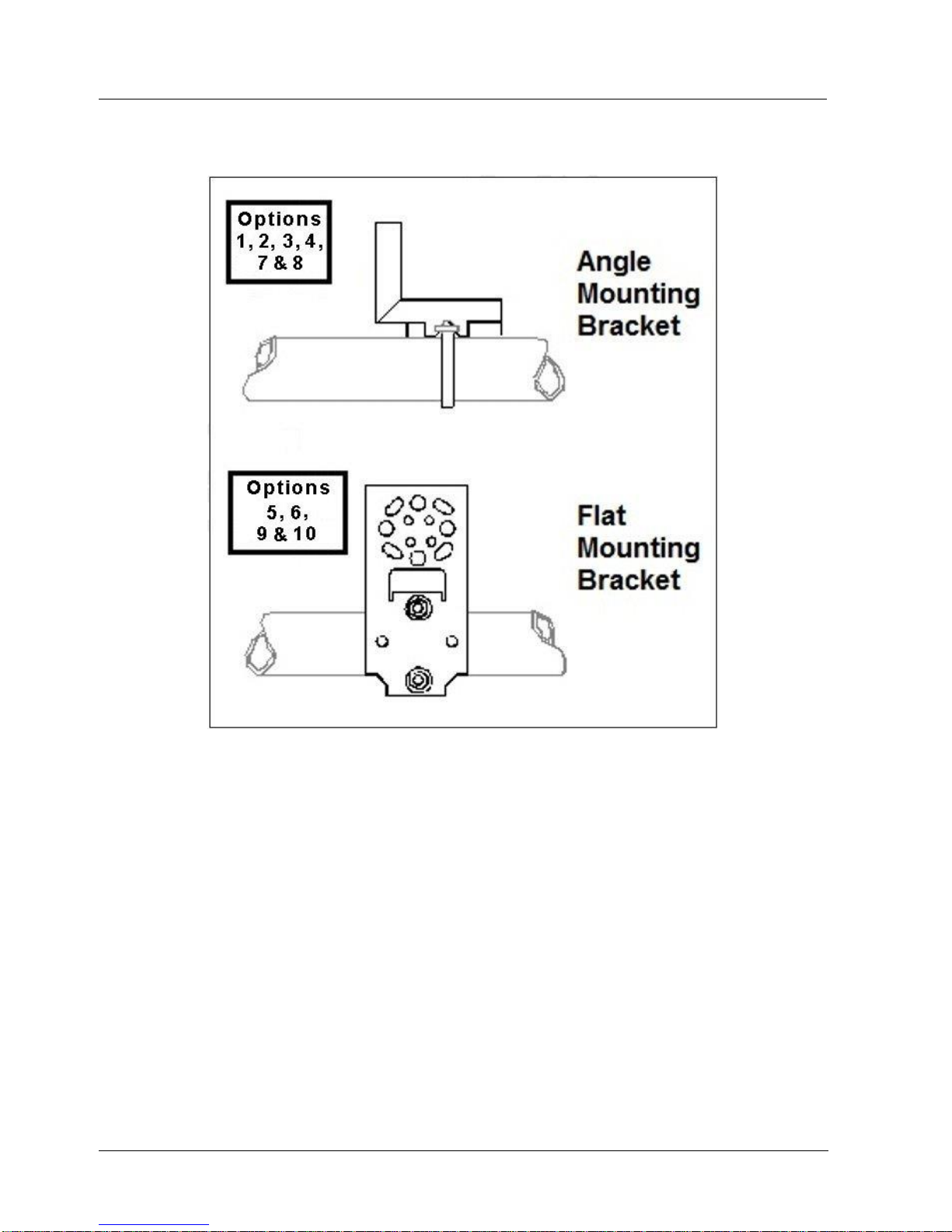
8. Parts
7.8. Transmitter body
76 SmartLine Wireless User's Manual Revision 2
Mounting Brackets
Figure 8-1: Angle and Flat Bracket Parts
Page 91

8. Parts
7.8. Transmitter body
Revision 2 SmartLine Wireles User's Manual 77
Table 8-2: Angle and Flat Bracket Parts (Refer to Figure 8-1)
Key
No.
Part Number
Description
Quantity
Per Unit
1
30752770-603
SS 304 Angle Bracket Mounting kit for all models except Inline mount transmitters
1
2
30752770-604
SS 304 Angle Bracket Mounting kit for all In-Line mount
transmitters
1
5
51196557-505
SS 304 Flat Bracket Mounting kit for all models except In-line
mount transmitters
1
6
51196557-506
SS 304 Flat Bracket Mounting kit for all In-line transmitters
1
7
30752770-603
SS 316 Angle Bracket Mounting kit for all In-line transmitters
except In-Line mount transmitters
1
8
30752770-604
SS 316 Angle Bracket Mounting kit for all In-Line mount
transmitters
1
9
51196557-508
SS 316 Flat Bracket Mounting kit for all In-line transmitters
except In-Line mount transmitters
1
10
51196557-509
SS 316 Flat Bracket Mounting kit for all In-Line mount
transmitters
1
Table 8-3: Transmitter Enclosure O-Ring Kit
Key
No.
Part Number
Description
Quantity
Per Unit
K7
30757503-007
Electronics enclosure seals kit. Kit includes:
O-ring for transmitter end caps
O-ring for meter body to electronics housing
6
3
Table 8-4: Meter Body Parts
Part Number
Meter body
Figure No.
Key
No.
Specify
complete
number from
nameplate
DP Models
Figure 8-2
1
GP/AP HEAD Models
Figure 8-2
Figure 8-3
1
LGP/LAP Models
Figure 8-3
1
Flange Mount Models
Figure 8-5 and
Figure 8-6
1
Remote Diaphragm Seal Models
Figure 8-8
1
Page 92

8. Parts
7.8. Transmitter body
78 SmartLine Wireless User's Manual Revision 2
Table 8-5: Models STDW810, 820, 825, 830 & 870
(Ref. Figure 8-2 )
Key
No.
Part Number
Description
Qty/Kit
Meter body Gasket Kits
51452865-501
51452865-502
51452865-503
51452865-504
Glass Filled PTFE
VITON
100% PTFE
GRAPHITE
Each Meter body Gasket Kit includes:
K6
Gasket, Process Head (6 Gaskets / 1 Kit)
6
Ka
Gasket, Flange Adapter (6 Gaskets / 1 Kit)
6
K7
O-Ring, meter body to Electronics Housing (3 Gaskets / 1
Kit)
3
K6 Process Head Gasket Kits
K6
K6
K6
51452868-501
51452868-502
51452868-507
Gasket only, Process Head (12 PTFE Gaskets/pack)
Gasket only, Process Head (6 Viton Head O-Rings)
Gasket only, Process Head Graphite Gasket (use only as
replacement of existing graphite gasket)
12
6
6
Ka Flange Adapter Gasket Kits
Ka
Ka
Ka
51452868-504
51452868-505
51452868-508
Gasket only, Flange Adapter, 6 PTFE Adapter Gaskets
Gasket only, Flange Adapter, 6 VITON Adapter O-Rings
Gasket only, Flange Adapter Graphite Gasket (use only
as replacement of existing graphite gasket)
6
6
6
½-Inch NPT Flange Adapter Kits
51452867-110
51452867-210
51452867-310
51452867-410
51452867-150
51452867-350
51452867-130
51452867-330
Flange Adapter Kit, with:
SS Flange Adapters and with carbon steel bolts
SS Flange Adapters and with A286 SS (NACE) bolts
SS Flange Adapters and with 316 SS (non-NACE) bolts
SS Flange Adapters and with B7M alloy steel bolts
Monel Flange Adapters and with carbon steel bolts
Monel Flange Adapters and with 316 SS (non-NACE)
bolts
Hastelloy C Flange Adapters and with carbon steel bolts
Hastelloy C Flange Adapters and with 316 SS (nonNACE) bolts
Each 1/2-inch NPT Flange Adapter Kit includes:
Ka
Gasket, Flange Adapter
2
Kb
1/2-inch NPT Flange Adapter
2
Kc
Bolt, hex head, 7/16-20 UNF, 1.50 inches long
4
Page 93

8. Parts
7.8. Transmitter body
Revision 2 SmartLine Wireles User's Manual 79
Bolt and Nut Kit
51452866-501
Carbon steel bolt and Nut Kit
51452866-502
Stainless Steel Bolt and Nut Kit with NACE Certificate
51452866-503
Stainless Steel Bolt and Nut Kit without NACE Certificate
51452866-504
B7M Bolt and Nut Kit
51452866-505
All Stainless Steel Bolt and Nut Kit with NACE
51452866-506
Monel Bolt and Nut Kit
51452866-507
Duplex Bolt and Nut Kit
51452866-508
Stainless Steel Bolt and Nut Kit with NACE 6K
Each Bolt and Nut Kit Includes:
K8
Head Bolt
4
K4
Head Nut
4
Kc
Adapter Bolt
4
Page 94
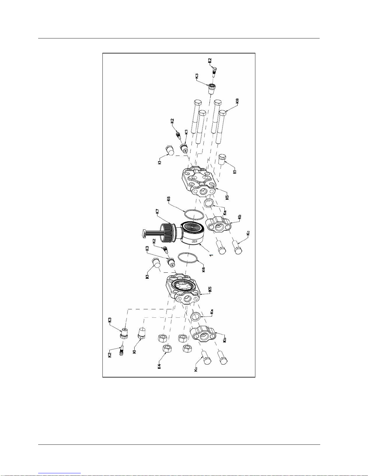
8. Parts
7.8. Transmitter body
80 SmartLine Wireless User's Manual Revision 2
Figure 8-2: Models STDW810, 820, 825, 830, & 870
(Ref. Table 8-5)
Page 95

8. Parts
7.8. Transmitter body
Revision 2 SmartLine Wireles User's Manual 81
Table 8-6: Parts for STGW830, 840, 870 and STAW822, 840 Transmitter Body
(Ref. Figure 8-3)
Key
No.
Part Number
Description
Qty/Unit
Process Head Assembly Kits with PTFE Gaskets
51452864-010
51452864-012
51452864-020
51452864-022
51452864-030
51452864-032
51452864-040
51452864-042
51452864-050
51452864-052
Carbon steel head (zinc plated) without side vent/drain
Carbon steel head (zinc plated) with side vent/drain
Stainless steel head without side vent/drain
Stainless steel head with side vent/drain
Hastelloy C head without side vent/drain
Hastelloy C head with side vent/drain
Monel head without side vent/drain
Monel head with side vent/drain
Carbon steel head (nickel plated) without side vent/drain
Carbon steel head (nickel plated) with side vent/drain
Process Head Assembly Kits with VITON Gaskets
51452864-110
51452864-112
51452864-120
51452864-122
51452864-130
51452864-132
51452864-140
51452864-142
51452864-150
51452864-152
Carbon steel head (zinc plated) without side vent/drain
Carbon steel head (zinc plated) with side vent/drain
Stainless steel head without side vent/drain
Stainless steel head with side vent/drain
Hastelloy C head without side vent/drain
Hastelloy C head with side vent/drain
Monel head without side vent/drain
Monel head with side vent/drain
Carbon steel head (nickel plated) without side vent/drain
Carbon steel head (nickel plated) with side vent/drain
Each process head assembly kit includes:
K1
Pipe Plug (See notes 1 & 2)
1
K2
Vent Plug (See note 1)
1
K3
Vent Bushing (See note 1.)
1
K5
Process Head
1
K6
Gasket (PTFE), Process Head
1
Ka
Gasket (PTFE), Flange Adapter
1
Notes
Note 1: This item is made of the same material as the Process Heads, except for Kits with
carbon steel Process Heads, which include stainless steel Pipe Plug, Vent Plug, and Vent
Bushing.
Note 2: The Kit for Process Heads without side vent/drain does not include Pipe Plugs (K1).
Reference Head
K9
51452951-502
316 SS Blind Reference Head
11
Page 96

8. Parts
7.8. Transmitter body
82 SmartLine Wireless User's Manual Revision 2
Bolt and Nut Kit
51452866-501
Carbon steel bolt and Nut Kit
51452866-502
Stainless Steel Bolt and Nut Kit with NACE Certificate
51452866-503
Stainless Steel Bolt and Nut Kit without NACE Certificate
51452866-504
B7M Bolt and Nut Kit
51452866-505
All Stainless Steel Bolt and Nut Kit with NACE
51452866-506
Monel Bolt and Nut Kit
51452866-507
Duplex Bolt and Nut Kit
51452866-508
Stainless Steel Bolt and Nut Kit with NACE 6K
Each Bolt and Nut Kit Includes:
K8
Head Bolt
4
K4
Head Nut
4
Kc
Adapter Bolt
4
Page 97
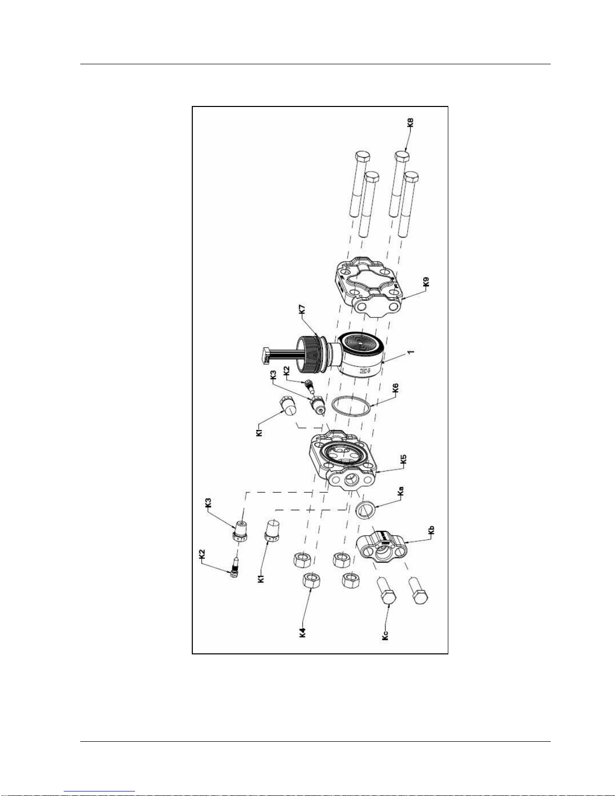
8. Parts
7.8. Transmitter body
Revision 2 SmartLine Wireles User's Manual 83
Figure 8-3: STGW830, 840, 870, and STAW822, 840 Transmitter Body
(Ref. Table 8-6)
Page 98
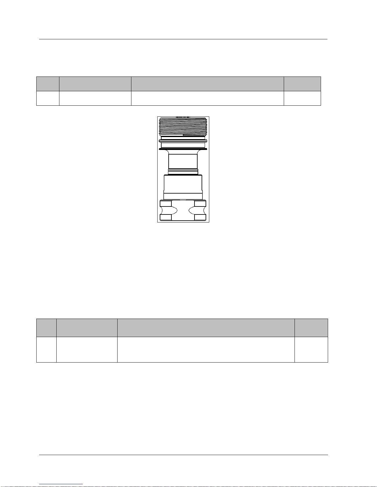
8. Parts
7.8. Transmitter body
84 SmartLine Wireless User's Manual Revision 2
Table 8-7: Inline Gauge and Inline Atmospheric Meter Body Parts
Key
No.
Part Number
Description
Qty/Unit
Specify complete model
number from nameplate
STW Series replacement meter body (LAP/LGP
model)
1
Figure 8-4: Inline Gauge and Inline Atmospheric Display Bodies
Table 8-8: Flange-Mounted Meter Body Parts
(Refer to Figure 8-5 and Figure 8-6)
Key
No.
Part Number
Description
Qty/Unit
1
Specify complete
model number from
nameplate
STW Series 800 replacement meter body
1
Page 99
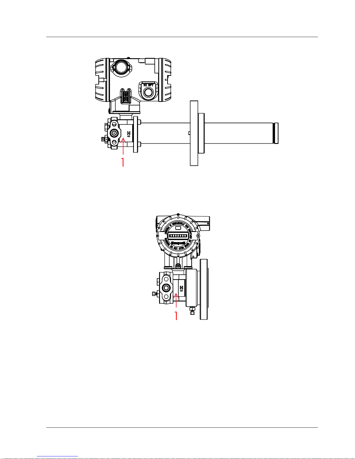
8. Parts
7.8. Transmitter body
Revision 2 SmartLine Wireles User's Manual 85
Figure 8-5: Extended Flange Design
Figure 8-6: Pseudo Flange design
Page 100
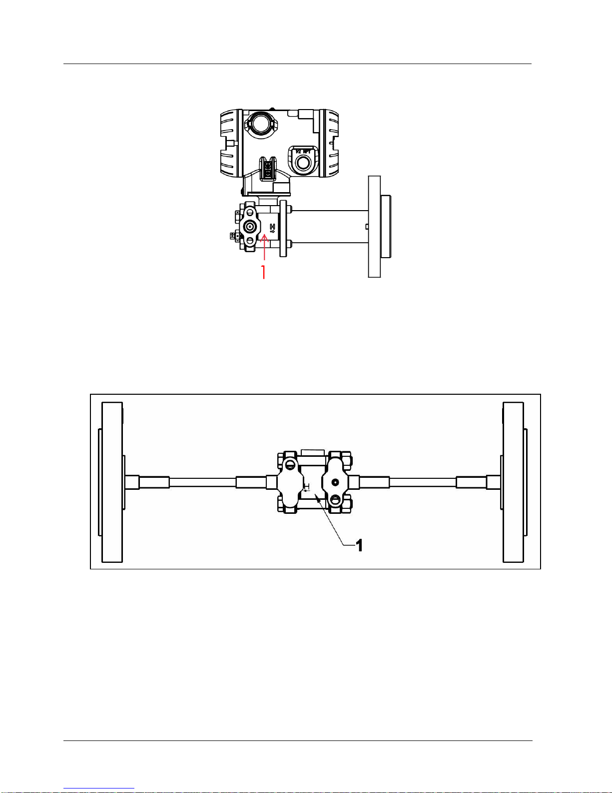
8. Parts
7.8. Transmitter body
86 SmartLine Wireless User's Manual Revision 2
Figure 8-7: Flush Flange Design
Figure 8-8: Remote Seal Diaphragm
No replacement meter body (Key No.1) is available for Remote Diaphragm Seal models
 Loading...