

Page 1

INSTALLATION AND
MAINTENANCE INSTRUCTIONS
IDP-Zone-6
Six Zone Interface Module
BEFORE INSTALLING
If the modules will be installed in an existing operational
system, inform the operator and local authority that the
system will be temporarily out of service. Disconnect the
power to the control panel before installing the modules.
This system contains static sensitive components. Always
ground yourself with a proper wrist strap before handling
any circuits so that static charges are removed from the
body. The module housing should also be grounded.
NOTICE: This manual should be left with the owner/user
of this equipment.
GENERAL DESCRIPTION
The IDP-Zone-6 Six Zone Interface Module is intended
for use in an intelligent alarm system. Each module pro-
SPECIFICATIONS
Normal Operating Voltage: 15-32 VDC
Stand-By Current: 2 mA
Alarm Current: 40 mA (assumes all six
LEDs solid on)
Temperature Range: 32ºF to 120ºF ( 0ºC to 49ºC)
Humidity: 10 to 93% Non-condensing
Dimensions: 6.8˝ H x 5.8˝ W x 1.0˝ D
Accessories: IDP-ACB Cabinet and chassis
Wire Gauge: 12-18 AWG
Max. IDC Wiring Resistance: 25 ohms
External Supply Voltage
DC Voltage: 18-28 volts power limited
Ripple Voltage: 0.1 volts RMS maximum
Current: 90mA per module
IDC: Supervised and power limited
vides an interface between the intelligent alarm system
and a conventional alarm system loop. A common SLC
input is used for all modules, and the initiating device
loops share a common supervisory supply and ground.
Otherwise, each monitor operates independently from the
others. Each module has its own unique address.
A pair of rotary code switches is used to set the address
of the first module from 01 to 94. The remaining modules
are automatically assigned to the next five higher addresses. Provisions are included for disabling a maximum
of two unused modules to release the addresses to be
used elsewhere. Each module also has panel controlled
bicolor LED indicators. The panel can cause the LEDs to
blink, latch on, or latch off.
Compatible Two-wire System Sensor Smoke Detectors for use with IDP-Zone-6
DET. DETECTOR
MODEL DET. ID MANUFACTURER BASE MODEL MAX DET.
1151 A SYSTEM SENSOR B110LP, B401 20
1451 A SYSTEM SENSOR B401, B401B 20
1451DH A SYSTEM SENSOR DH400 20
2151 A SYSTEM SENSOR B110LP, B401 20
2451 A SYSTEM SENSOR DH400, B401B, B401 20
2451TH A SYSTEM SENSOR B401, B401B 20
5451 A SYSTEM SENSOR B401 20
1100 A SYSTEM SENSOR N/A 20
1400 A SYSTEM SENSOR N/A 20
** 2100AT A SYSTEM SENSOR N/A 20
2100B A SYSTEM SENSOR N/A 20
2100D A SYSTEM SENSOR N/A 20
2100S A SYSTEM SENSOR N/A 20
2100TB A SYSTEM SENSOR N/A 20
2100TD A SYSTEM SENSOR N/A 20
2100TS A SYSTEM SENSOR N/A 20
2300B A SYSTEM SENSOR N/A 20
2300TB A SYSTEM SENSOR N/A 20
2400 A SYSTEM SENSOR N/A 20
2400TH A SYSTEM SENSOR N/A 20
* 2W-B A SYSTEM SENSOR N/A 20
* 2W-TB A SYSTEM SENSOR N/A 20
DH100LP A SYSTEM SENSOR N/A 20
* Class B, Style B only
** No Accessory will be supported by 2100AT
K200-16-00 1 I56-2733-003
Page 2
Backbox
Mounting
Holes
2
3
1
Included:
0
1
2
3
4
5
6
7
8
9
0
7
8
6
5
4
3
2
1
9
1
0
1
1
1
2
1
3
1
4
1
5
BASE
ADDRESS
ADDRESS
DISABLE
N
O
N
E
O
N
E
T
W
O
T
H
R
E
E
0
1
2
3
4
5
6
7
8
9
0
7
8
6
5
4
3
2
1
9
10
1
1
1
2
1
3
1
4
1
5
BASE
ADDRESS
ADDRESS
DISABLE
NONE
ONE
TW
O
THREE
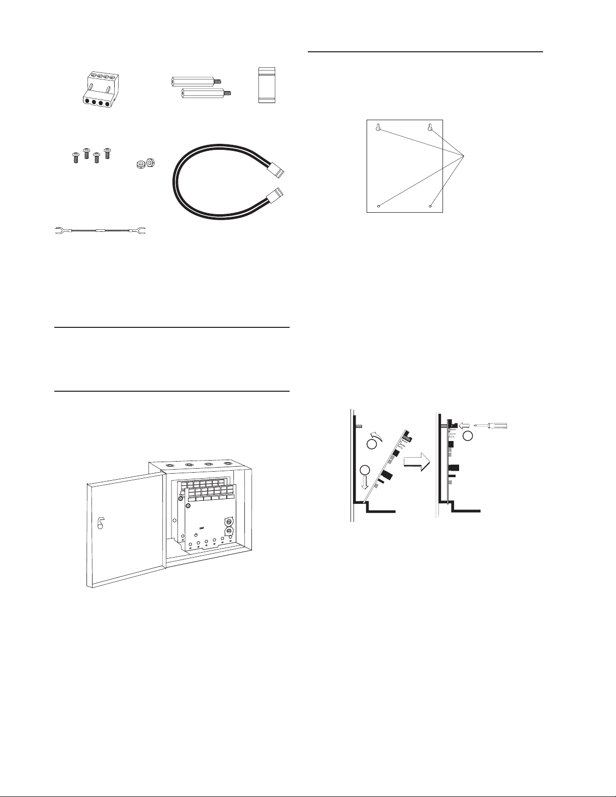
(5) 1 x 4 Terminal Blocks (2) 11/4˝ Stand offs (3) Shunts
(4) Machine Screws (1) Long Power Supply Jumper
(2) Nuts
(6) 3.9k Ohm
End of Line Resistors
Shipped on Board:
(2) Shunts in Class A/B position
(Shipped in Class B position, remove shunts for Class A)
COMPATIBILITY REQUIREMENTS
To ensure proper operation, this module shall be connected to a compatible Silent Knight system control panel
(list available from Silent Knight).
COMPONENTS
The following is a description of the IDP-Zone-6 mounting framework:
• One or two IDP-Zone-6 modules can be installed in a
IDP-ACB cabinet
INSTALLATION STEPS
1. Cabinet Mounting
In a clean, dry area, mount the backbox using the
four holes provided in the back surface of the cabinet
(Figure 2).
Figure 2: Typical mounting hole locations
C0235-00
2. Module Installation
There are two methods for installing a module in the
rear position of a chassis. Method one is for installation of a rear module only, when no module will be installed in front of it. Refer to Figure 3 for instructions.
Method two is for installation of a rear module when
another module will be installed in the chassis position
in front of it. Refer to Figures 4a and 4b for method
two. All necessary screws and standoffs are supplied
with the modules.
C0237-00
Figure 3: Installation of rear module only, method one
C0234-04
Step 1: Insert the bottom of the IDP-Zone-6 module
down into a rear slot on the chassis.
Figure 1: IDP-ACB Cabinet
The IDP-ACB cabinet has a built-in chassis that will accommodate one or two IDP-Zone-6 modules. For cabinet
dimensions refer to the IDP-ACB instruction manual.
The front IDP-Zone-6 module positions of each chassis
are offset below the rear IDP-Zone-6 module positions so
that all of the status indicators are visible.
Step 2: Carefully swing the upper edge of the board
back towards the back of the chassis until it
touches the two standoffs.
Step 3: Align two 4-40 screws with the two standoffs
and tighten.
Step 4: Address and wire the modules according to the
instructions in this manual.
K200-16-00 2 I56-2733-003
Page 3
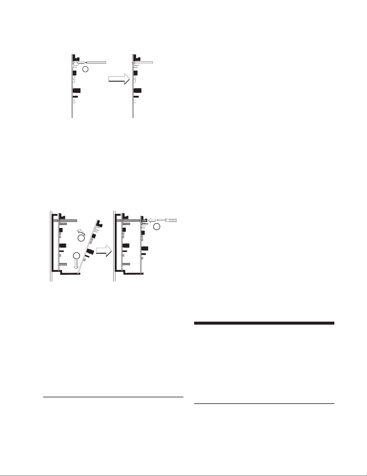
The steps in Figures 4a and 4b describe and illustrate mod-
1
2
3
1
ule installation when the rear chassis position and the position in front of it will be filled. Front position installation
is possible only if the rear position is filled with a module.
C0225-00
Figure 4a: Installation of IDP-Zone-6 module in a rear
chassis position, method two
Step 1: Insert the bottom edge of the IDP-Zone-6
module down into a rear slot of the chassis.
Step 2: Carefully swing the upper edge of the board
towards the back of the chassis until it touches
the short standoff attached to the chassis.
Step 3: Align the long standoff with the short standoff
and tighten.
C0226-00
Figure 4b: Installation of IDP-Zone-6 module in
front chassis position
Step 1: Insert the bottom edge of the IDP-Zone-6
module down into a front slot of the chassis.
Step 2: Carefully swing the upper edge of the board
towards the back of the chassis until it touches
the 11/4˝ (31.75mm) standoffs installed on the
rear module.
Step 3: Align two 4-40 screws with the two standoffs
and tighten.
Step 4: Address and wire the modules according
to the instructions in this manual.
2. All wiring to the IDP-Zone-6 is done via terminal
blocks. In order to properly make electrical connections strip approximately 1/4˝ of insulation from the
end of wire, sliding the bare end of the wire under the
clamping plate screw.
3. Set the address on the modules per the job drawing. Use
the rotary code switches to set the address of the first
module (between 01 and 94).
In Class B operation, the remaining modules are automatically assigned to the next five higher addresses. For example, if the base address switch is set to 28, the next five
modules will be addressed to 29, 30, 31, 32 and 33.
The module is shipped in Class B position, remove
shunts for Class A. When operating in Class A, alternate
modules are paired together (+0/+1, +2/+3, +4/+5), resulting in a total of three modules. For example, if the
base address switch is set to 28, then 30 and 32 will be
automatically assigned to the modules while 29, 31 and
33 are available to be used for other modules on the SLC.
For Class A and B operation, DO NOT set the lowest address above 94, as the other modules will be assigned to
nonexistent addresses.
NOTE: The IDP-Zone-6 must have power cycled for
shunt changes to take effect.
4. A shunt is provided to disable a maximum of two
unused modules in Class B operation and Class A operation. Modules are disabled from the highest address
and work downward. If two modules are disabled, the
lowest four addresses will be functional, while the
highest two will be disabled. For example, in Class B
operation, if the shunt for Address Disable is placed
on “two” and the base switch is set to 28, the modules
will be assigned to 28, 29, 30 and 31 while disabling
the highest two positions.
NOTE: Place unused shunts on single pin to store on
board for future use.
WIRING NOTES
• Power-limited circuits must employ type FPL, FPLR,
or FPLP cable as required by Article 760 of the NEC.
• All wiring must be in accordance with the NEC,
NFPA 72 and all other applicable codes and standards.
All external power supplies must be power limited
with battery back-up. All external power supplies and
detectors must be UL listed for fire protection
signaling applications.
WIRING
NOTE: All wiring must conform to applicable local
codes, ordinances, and regulations.
1. Install module wiring in accordance with the job drawings and appropriate wiring diagrams.
PROGRAMMING
The modules are programmed as devices in each system
according to the programming instructions in the appropriate FACP manual.
K200-16-00 3 I56-2733-003
Page 4
0
1
2
3
4
5
6
7
8
9
BASE ADDRESS
TO NEXT DEVICE
–
STATUS
INDICATORS
—
+
—
+
+0
+1
IDC
ADDRESS
—
+
—
+
+2
+3
IDC
ADDRESS
—
+
—
+
+4
+5
IDC
ADDRESS
SLC
—
+
—
+
+
–
+
FROM PANEL OR
PREVIOUS DEVICE
3.9K EOL
RESISTOR
(INCLUDED)
CONNECT MODULES TO
LISTED COMPATIBLE
SILENT KNIGHT CONTROL
PANELS ONLY
SIGNAL LINE CIRCUIT (SLC) 32 VDC MAX.
SEE PANEL INSTRUCTION MANUAL
FOR WIRE REQUIREMENTS.
CLASS B IDC (TYPICAL)
A/B SELECT
A/B SELECT
DISABLE 1
DISABLE 2
+
–
+
–
T6
T5
DETECTORS MUST BE UL LISTED COMPATIBLE WITH THE MODULE.
INSTALL DETECTORS PER MANUFACTURER'S INSTALLATION INSTRUCTIONS.
(–)
(+)
IN
OUT
—
+
—
+
EXTERNAL SUPPLY
0
1
2
3
4
5
6
7
8
9
POWER-LIMITED
AND SUPERVISED
POWER TO THE NEXT INTERFACE
MODULE MUST BE EXTERNALLY
SWITCHED TO RESET THE DETECTORS.
AN FRM-1 RELAY CONTROL MODULE CAN BE
USED TO SWITCH POWER FROM A
STANDARD POWER SUPPLY. SEE FIGUR 10.
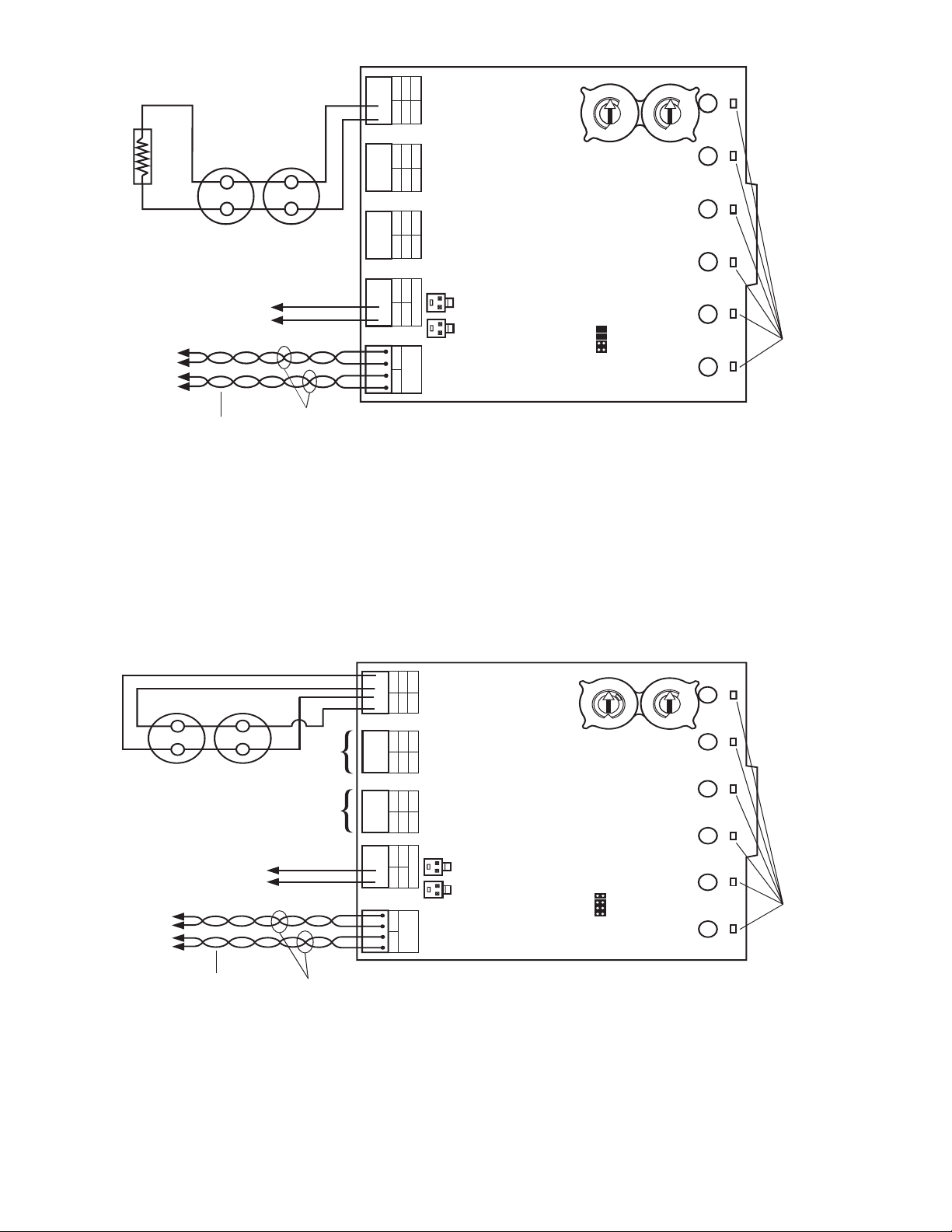
Figure 5: Interface two-wire conventional detectors – Class B, Style B.
0
1
2
3
4
5
6
7
8
9
BASE ADDRESS
TO NEXT DEVICE
–
STATUS
INDICATORS
—
+
—
+
+0
+1
IDC
ADDRESS
—
+
—
+
+2
+3
IDC
ADDRESS
—
+
—
+
+4
+5
IDC
ADDRESS
SLC
—
+
—
+
+
–
+
FROM PANEL OR
PREVIOUS DEVICE
CONNECT MODULES TO LISTED COMPATIBLE
SILENT KNIGHT CONTROL PANELS ONLY
SIGNAL LINE CIRCUIT (SLC) 32 VDC MAX.
SEE PANEL INSTRUCTION MANUAL
FOR WIRE REQUIREMENTS.
CLASS A IDC (TYPICAL)
A/B SELECT
A/B SELECT
DISABLE 1
DISABLE 2
0
1
2
3
4
5
6
7
8
9
+
+
IDC 2
IDC 3
(–)
(+)
POWER TO THE NEXT INTERFACE
MODULE MUST BE EXTERNALLY
SWITCHED TO RESET THE DETECTORS.
AN FRM-1 RELAY CONTROL MODULE CAN BE
USED TO SWITCH POWER FROM A
STANDARD POWER SUPPLY. SEE FIGURE 10.
T6
T5
IN
OUT
—
+
—
+
EXTERNAL SUPPLY
POWER-LIMITED
AND SUPERVISED
–
–
DETECTORS MUST BE UL LISTED COMPATIBLE WITH THE MODULE. INSTALL
DETECTORS PER MANUFACTURER'S INSTALLATION INSTRUCTIONS.
1. To use a common power supply between multiple IDPZone-6 modules, connect a long power supply jumper from
T5 or T6 to T5 or T6 on the adjacent IDP-Zone-6 module.
C0812-01
K200-16-00 4 I56-2733-003
1. To select Class A, remove the two shunts from the
“A/B select” positions.
2. To use a common power supply between multiple IDPZone-6 modules, connect a long power supply jumper from
T5 or T6 to T5 or T6 on the adjacent IDP-Zone-6 module.
Figure 6: Interface two-wire conventional detectors – Class A, Style D.
C0813-01
Page 5
9
8
7
6
5
4
3
2
1
0
ADDRESS
LOOP
RELAY
CONTROL
MODULE
(+)
(–)
FROM
PANEL OR
PREVIOUS
DEVICE
(+
)
(–
)
POWER LIMITED
DC POWER SUPPLY,
LISTED FOR FIRE
PROTECTION
WITH BATTERY
BACKUP
(+)
(–)
TO NEXT
(+
)
(–
)
DEVICE
CONNECT MODULES
TO LISTED COMPATIBLE
CONTROL PANELS ONLY.
TWISTED PAIR
IS RECOMMENDED
(+)
(–)
SIGNAL LINE CIRCUIT (SLC)
32 VDC MAX.
—
+
—
+
+0
+1
IDC
ADDRESS
—
+
—
+
+2
+3
IDC
ADDRESS
—
+
—
+
+4
+5
IDC
ADDRESS
SLC
—
+
—
+
A/B SELECT
A/B SELECT
DISABLE 1
DISABLE 2
T6
T5
—
+
—
+
+0
+1
IDC
ADDRESS
—
+
—
+
+2
+3
IDC
ADDRESS
—
+
—
+
+4
+5
IDC
ADDRESS
SLC
—
+
—
+
A/B SELECT
A/B SELECT
DISABLE 1
DISABLE 2
T6
T5
IN
OUT
—
+
—
+
EXTERNAL SUPPLY
IN
OUT
—
+
—
+
EXTERNAL SUPPLY
EXTERNAL
POWER
SUPPLY
—
+
PCB 1
PCB 2
VIEW A-A
0
1
2
3
4
5
6
7
8
9
BASE ADDRESS
0
1
2
3
4
5
6
7
8
9
0
1
2
3
4
5
6
7
8
9
BASE ADDRESS
0
1
2
3
4
5
6
7
8
9
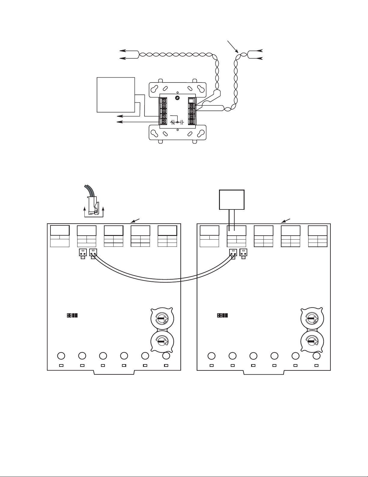
Figure 7: Relay control module used to disconnect a power supply.
C0248-01
Figure 8: Example of multiple boards sharing same external supply. Refer to figures 8 and 9 for typical wiring.
Make certain lip on long power supply jumper engages retaining tab on T5 or T6 as shown in View A-A.
K200-16-00 5 I56-2733-003
C0142-01
Page 6

7550 Meridian Circle
Maple Grove, MN 55369-4927
763-493-6455; 800-328-0103
Fax: 763-493-6475
http://www.silentknight.com
© 2006 Silent Knight 2/06
FCC Statement
This device complies with part 15 of the FCC Rules. Operation is subject to the following two conditions: (1) This device may not cause harmful interference, and (2) this device must accept any interference received, including interference that may cause undesired operation.
NOTE:
This equipment has been tested and found to comply with the limits for a Class B digital device, pursuant to Part 15 of the FCC Rules.
These limits are designed to provide reasonable protection against harmful interference in a residential installation. This equipment
generates, uses and can radiate radio frequency energy and, if not installed and used in accordance with the instructions, may cause harmful
interference to radio communications. However, there is no guarantee that interference will not occur in a particular installation. If this
equipment does cause harmful interference to radio or television reception, which can be determined by turning the equipment off and on,
the user is encouraged to try to correct the interference by one or more of the following measures:
– Reorient or relocate the receiving antenna.
– Increase the separation between the equipment and receiver.
– Connect the equipment into an outlet on a circuit different from that to which the receiver is connected.
– Consult the dealer or an experienced radio/TV technician for help.
K200-16-00 6 I56-2733-003
 Loading...