

Page 1
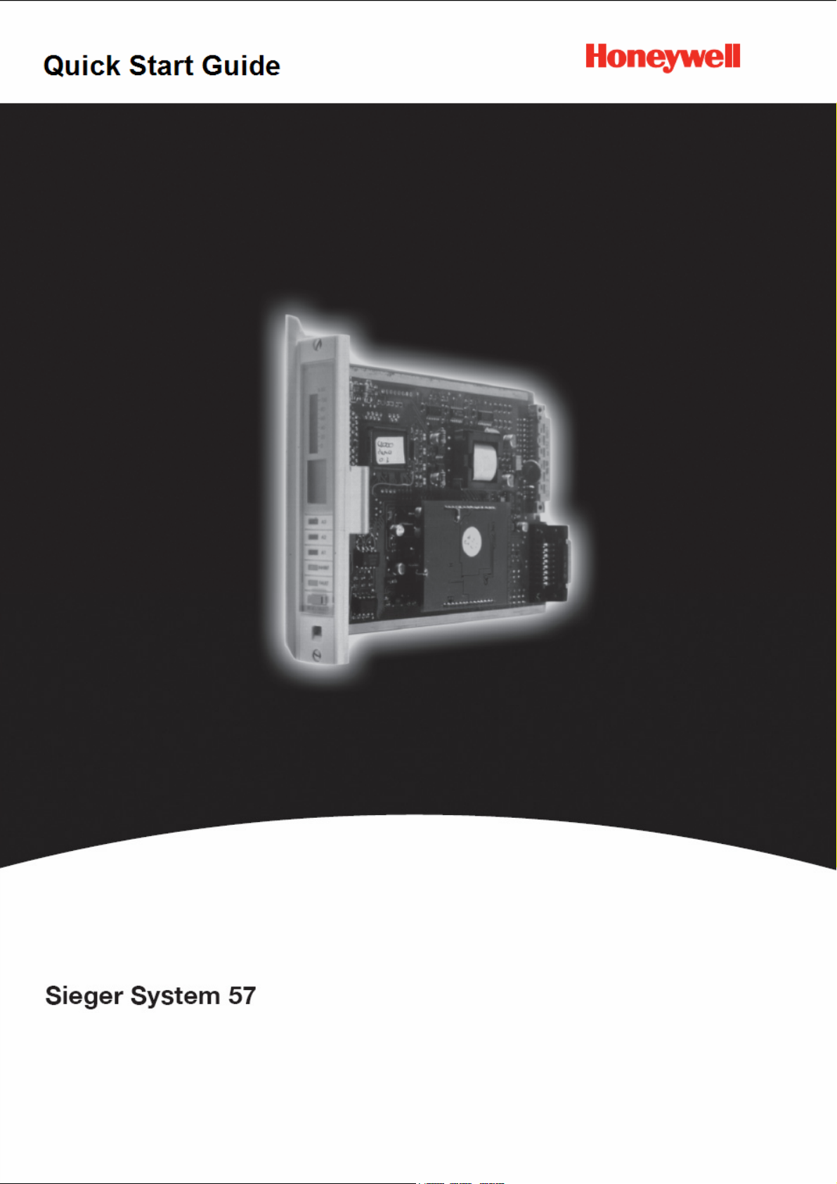
System 57 Quick Start Guide 05701-M-5026 MAN0839 Issue 1
0
Page 2

System 57 Quick Start Guide 05701-M-5026 MAN0839 Issue 1
1 Contents
1 Contents............................................................................................................................... 1
2 Safety................................................................................................................................... 2
3 Introduction .......................................................................................................................... 3
3.1 Gas Control Cards......................................................................................................... 3
3.2 Fire Control Cards ......................................................................................................... 3
3.3 Master Alarm Update Panel .......................................................................................... 3
3.4 Power Supply Units ....................................................................................................... 3
3.5 Engineering Card .......................................................................................................... 4
3.5.1 Serial Communications Module .............................................................................. 4
3.5.2 RS232 Printer Driver Module.................................................................................. 4
3.5.3 Master Alarm Update Module ................................................................................. 4
3.6 Interface Cards.............................................................................................................. 4
3.7 Rack Assemblies........................................................................................................... 4
3.8 Cabinet Assemblies....................................................................................................... 4
3.9 DC Input Card ............................................................................................................... 5
4 System Overview ................................................................................................................. 6
5 Cabinet and Rack Installation .............................................................................................. 7
6 Detector Installation ............................................................................................................. 7
7 Interface Card Connections ................................................................................................. 8
8 Detector Connections .......................................................................................................... 9
8.1 Cable Earthing/Grounding............................................................................................. 9
8.2 5701 Gas Card and Catalytic Type Detector................................................................. 9
8.3 5701 Gas Card and 2 Wire Loop Powered Detectors ................................................... 9
8.3.1 4-20mA loop powered detector (measuring resistor in supply return) .................. 10
8.3.2 4-20mA loop powered detector (measuring resistor in supply positive line)......... 10
8.4 5701 Gas Card and 3 Wire 4-20mA Transmitter......................................................... 10
8.4.1 3 Wire Source Transmitter (sink card) .................................................................. 11
8.4.2 3 Wire Sink Transmitter (source card) .................................................................. 11
8.5 5704 Gas Card and Catalytic Type Detector............................................................... 12
8.6 5704 Gas Card and 2 Wire Loop Powered Detectors ................................................. 12
8.6.1 4-20mA loop powered detector (measuring resistor in supply return) .................. 12
8.7 5704 Gas Card and 3 Wire 4-20mA Transmitter......................................................... 13
8.8 5704 Fire Card ............................................................................................................ 14
8.8.1 Line Resistance .................................................................................................... 14
8.8.2 Typical Loop Powered Detector Connections....................................................... 15
8.8.3 Typical Loop Powered Detector with IS Barrier Connections ............................... 15
8.8.4 Separately Powered Detectors ............................................................................. 16
8.8.5 Call Points and Simple Switched Output Detectors.............................................. 17
8.8.6 Detectors with Voltage Free Contact Outputs ...................................................... 18
9 Specification....................................................................................................................... 20
9.1 Approvals and Standards ............................................................................................ 20
9.2 Environmental ............................................................................................................. 21
9.3 RFI/EMC Conformity ................................................................................................... 21
10 Special Conditions For Safe Use. .................................................................................... 22
1
Page 3

System 57 Quick Start Guide 05701-M-5026 MAN0839 Issue 1
2 Safety
Ensure that you read and understand these instructions BEFORE operating the equipment.
Please pay particular attention to the Safety Warnings.
WARNINGS
The items of equipment covered by this manual are:
1. Not designed or certified for use in hazardous areas.
2. Designed for indoor use only.
3. Not to be exposed to rain or moisture.
CAUTIONS
1. Use only approved parts and accessories with the System 57 control
system.
2. To maintain safety standards, regular maintenance, calibration and
operation of the System 57 control system by qualified personnel is
essential.
IMPORTANT NOTICES
1. Honeywell Analytics can take no responsibility for installation and/or
use of its equipment if this is not done in accordance with the
appropriate issue and/or amendment of the manual.
2. The user of this manual should ensure that it is appropriate in all
details to the exact equipment to be installed and/or operated. If in
doubt, the user should contact Honeywell Analytics for advice.
Honeywell Analytics reserve the right to change or revise the information supplied in this
document without notice and without obligation to notify any person or organisation of such
revision or change. If further details are required which do not appear in this manual, contact
Honeywell Analytics or one of their agents.
2
Page 4

System 57 Quick Start Guide 05701-M-5026 MAN0839 Issue 1
3 Introduction
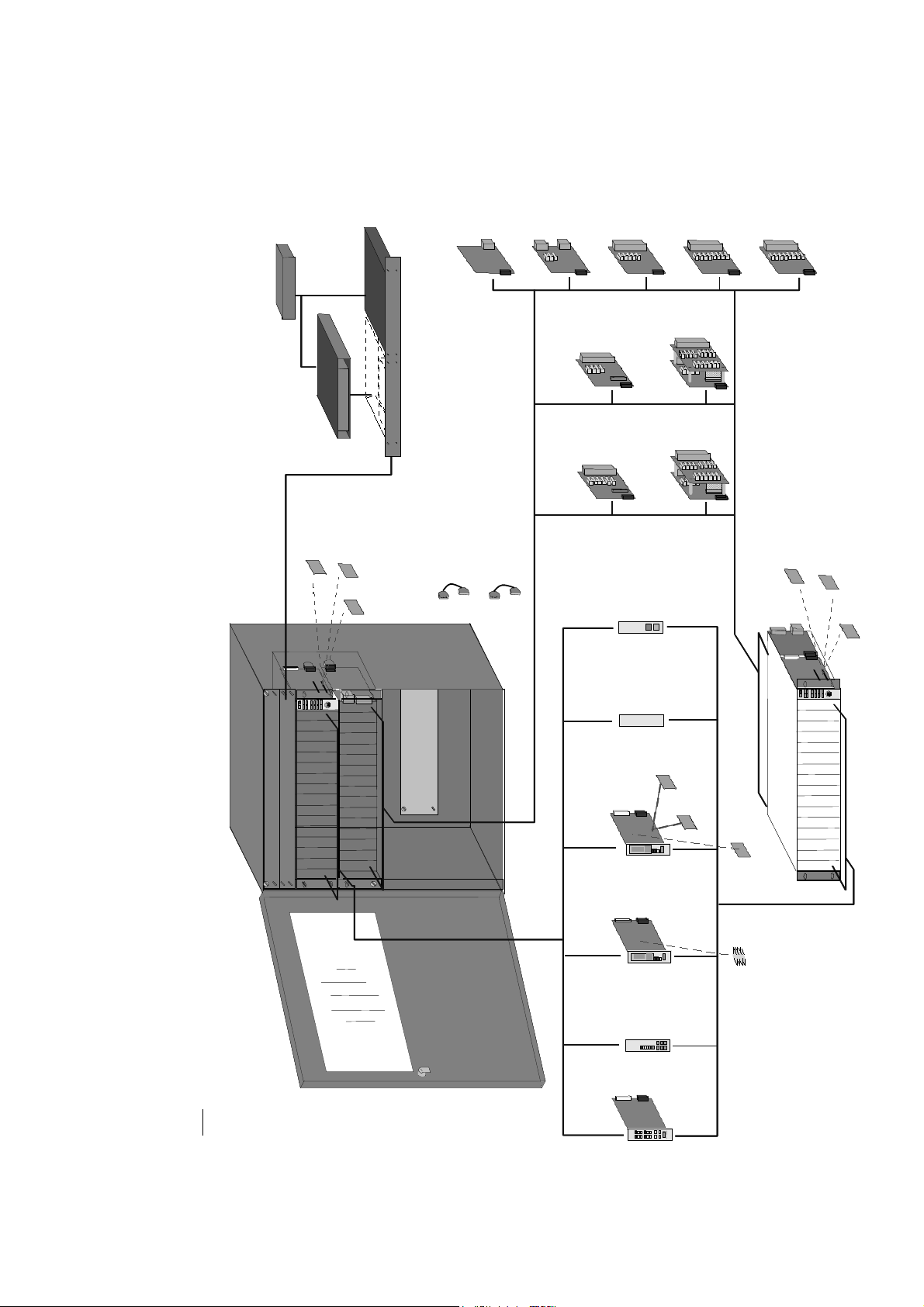
System 57 is a fire and or gas control system offering great flexibility through its modular
construction. The system is constructed in a rack that can be fitted with fire and/or gas
control cards and corresponding interface cards that allow connection of the associated
detectors. The rack can be panel or cabinet mounted. Further details of the main
components are given below. A graphical overview of all the available components and how
they can be assembled into a system is shown in section X. For further detailed information
refer to the individual operating manuals 05701-M-5001 (5701 gas control card), 05704-M5001 (5704 gas control card) and 05704-M-5002 (fire control card).
3.1 Gas Control Cards
The System 57 gas control cards provide display and alarm facilities for the full range of
Sieger gas detectors. Their back lit, multi-part LCD displays the gas reading and status in
both analogue bar graph and digital numeric forms. In addition, there is an alpha numeric
message section to give detector (and engineering function) status.
There is a choice of either the single channel 5701 or the four channel 5704 gas control
cards. Each card has two input options; one is for catalytic bridge type while the other is for 4
to 20mA detectors or transmitters. The control cards feature 3 levels of alarm, options of
individual, zoned, voted, master, time delayed, update and rate of rise alarm facilities, 4 part
LCD display, peak reading facility and detector performance monitoring.
3.2 Fire Control Cards
The 5704F fire control cards provide display and alarm facilities for a wide variety of fire
detection products and provide up to four fire zone inputs compatible with most flame,
smoke and heat detectors and manual call points. The status of each fire zone is individually
displayed by high intensity LEDs. In addition, each card has two line monitored alarm output
circuits. Both fire and gas control cards can be freely mixed in a rack. Up to 60 fire zones
can be monitored per 19" rack.
Each rack that contains a 5704F fire card has one 5704FS fire status panel fitted. The
5704FS fire status panel provides common display and alarm indication for all of the fire
cards in a rack as well as a local audible sounder. It also provides common push buttons for
executing specific fire card related functions.
3.3 Master Alarm Update Panel
The master alarm update facility can be enhanced by adding the optional master alarm
update panel which enables update facilities without the need for external wiring. The alarm
update panel is 1" wide and provides audible and visual alarms and a reset and accept push
button.
3.4 Power Supply Units
The power supply units are rack mounted to match the main control card rack design. The
units are 1U high, and available in 19" & ½ 19" sizes. Total maximum power capability is
200W (built in 50W blocks). The input voltage is auto sensing (AC or DC) and the output is
regulated DC with over voltage and overload protection.
3
Page 5

System 57 Quick Start Guide 05701-M-5026 MAN0839 Issue 1
3.5 Engineering Card
The System 57 engineering card provides full maintenance and set up facilities for each
channel card. The front panel has a series of tactile feedback push buttons that allows
checks of the alarm levels and performance to be carried out for each channel. A real-time
‘on board’ clock provides calibration history and calibration overdue reminder functions. An
access key provides security protection.
The engineering card can be fitted with optional modules for extended system options.
3.5.1 Serial Communications Module
The serial communications module provides a gateway between the System 57 rack and a
remote device (DCS, PLC or SCADA package) to allow the continuous monitoring of each
channel’s operation and condition as well as allowing remote configuration of the system
operation. The module uses the industry standard MODBUS RTU protocol, RS485/422/232
standard. Custom designed SCADA graphics packages are also available.
3.5.2 RS232 Printer Driver Module
The printer driver module provides a serial output in the event of a gas alarm, fault or user
intervention. The output is RS232 ASCII event data, has selectable print criteria, provides
time and date stamping and is electrically isolated.
3.5.3 Master Alarm Update Module
The alarm update module provides a common alarm indication with new alarm event update.
It also provides 2 Outputs: 1 relay, 1 Darlington, with selectable operation: pulsed or
continuous and an alarm and common alarm reset input. It complies with ISA ‘M’, DIN 19
235. It can be used with the optional master alarm update panel.
3.6 Interface Cards
There are 9 versions of interface card available (5 for 5701 Gas, 2 for 5704 Gas and 2 for
5704 Fire Control Cards). The interface cards provide the link between the various fire or
gas detectors and the control cards. They provide detector interface, offer flexible relay
options, and allow an individual control card power option. A high integrity relay operation
version is also available. The terminals accept ≤ 2.5mm
2
(14AWG) gauge cable.
3.7 Rack Assemblies
System 57 racking units provide mounting options for the system 57 control cards and
interface cards. The racks are available complete with a DC input card and an engineering
card. The racks are 3U high, with front or rear wiring options. Half and full 19" versions are
available accommodating up to a maximum of 64 channels of gas detection or 60 channels
of fire detection in a single rack, or a combination of both.
3.8 Cabinet Assemblies
The System 57 cabinets provide a convenient and compact mounting of the rack assemblies
and PSUs. They are wall mounting and available in half and full 19" versions. The cabinets
have an IP54/Nema 12 ingress protection rating, pre-formed bottom-entry knock-out gland
entries and an accessory mounting plate.
4
Page 6

System 57 Quick Start Guide 05701-M-5026 MAN0839 Issue 1
3.9 DC Input Card
The DC input card is connected directly to the engineering card and provides the connection
point for power supplied to the whole rack. The field wiring from the engineering card is also
on this card. It provides a common power supply wiring point, reverse polarity and short
circuit protection and multi-supply input capability.
5
Page 7
5701
Field Interface
05701-A-0326
5701
Field Interface
05701-A-0326
5701
Field Interface
05701-A-0326
5701
Field Interface
05701-A-0326
5701
Double SPCO
Relay Card
05701-A-0327
5701
Triple SPCO
Relay Card
05701-A-0328
5701
Triple DPCO
Relay Card
05701-A-0329
5701
High Integrity
Relay Card
5701
Double SPCO
Relay Card
05701-A-0327
5701
Triple SPCO
Relay Card
05701-A-0328
5701
Triple DPCO
Relay Card
5701
Double SPCO
Relay Card
05701-A-0327
5701
Triple SPCO
Relay Card
5701
Double SPCO
Relay Card
05701-A-0327
05701-A-0328
5701
Triple SPCO
Relay Card
05701-A-0328
05701-A-0329
5701
Triple DPCO
Relay Card
05701-A-0329
5701
Triple DPCO
Relay Card
05701-A-0329
05701-A-0330
5701
High Integrity
Relay Card
05701-A-0330
5701
High Integrity
Relay Card
05701-A-0330
5701
High Integrity
Relay Card
05701-A-0330
or
or
or
or
or
or
or
50W module +
(power upgrade)
05701-A-0440
50W module +
(power upgrade)
05701-A-0440
50W module +
(power upgrade)
05701-A-0440
50W module +
(power upgrade)
05701-A-0440
5704 Quad Relay
5704 Quad Relay
5704 Quad Relay
5704 Quad Relay
05701-A-0441
05701-A-0441
05701-A-0441
05701-A-0441
Subunit - 50W +
Subunit - 50W +
Subunit - 50W +
Subunit - 50W +
(for 16 way PSU only)
(for 16 way PSU only)
(for 16 way PSU only)
(for 16 way PSU only)
RS232 Printer
Drive module +
RS232 Printer
Drive module +
RS232 Printer
Drive module +
RS232 Printer
Drive module +
Alarm Update
module +
Alarm Update
module +
Alarm Update
module +
Alarm Update
module +
or
or
or
or
or
or
or
or
card ‡
card ‡
card ‡
card ‡
Engineering
Engineering
Engineering
Engineering
Power Supply Unit
(base unit = 50W)
16 way 05701-A-0405
8 way 05701-A-0406
Power Supply Unit
(base unit = 50W)
16 way 05701-A-0405
8 way 05701-A-0406
Power Supply Unit
(base unit = 50W)
Power Supply Unit
(base unit = 50W)
16 way 05701-A-0405
8 way 05701-A-0406
16 way 05701-A-0405
8 way 05701-A-0406
5704F Hex Relay
5704F Hex Relay
5704F Hex Relay
5704F Hex Relay
5701
Interconnect cable
05701-C-0390
5704 / 5704F
Interconnect cable
5701
Interconnect cable
05701-C-0390
5701
Interconnect cable
05701-C-0390
5701
Interconnect cable
05701-C-0390
Modbus Interface
module RS485/422/232 +
Modbus Interface
module RS485/422/232 +
Modbus Interface
module RS485/422/232 +
Modbus Interface
module RS485/422/232 +
DC
DC
DC
DC
Input ‡
Input ‡
Input ‡
Input ‡
5704 / 5704F
5704 / 5704F
5704 / 5704F
05704-C-0160
Interconnect cable
05704-C-0160
Interconnect cable
05704-C-0160
Interconnect cable
05704-C-0160
or
or
or
ororor
Interface card
05704-A-0121
Interface card
05704-A-0121
Interface card
05704-A-0121
Interface card
05704-A-0121
or
or
or
Interface card *
05704-A-0123
Interface card *
05704-A-0123
Interface card *
05704-A-0123
Interface card *
05704-A-0123
Master Alarm
Update panel +
05701-A-0339
Master Alarm
Update panel +
05701-A-0339
Master Alarm
Update panel +
05701-A-0339
Master Alarm
Update panel +
05701-A-0339
Blanking
Panel ‡
05701-A-0165
Blanking
Panel ‡
05701-A-0165
Blanking
Panel ‡
05701-A-0165
or
or
or
or
5704 Relay
Interface ass y
05704-A-0131
5704 Relay
Interface ass y
05704-A-0131
5704 Relay
Interface ass y
05704-A-0131
5704 Relay
Interface ass y
05704-A-0131
5704F Relay
Interface ass y *
05704-A-0133
5704F Relay
Interface ass y *
05704-A-0133
5704F Relay
Interface ass y *
05704-A-0133
5704F Relay
Interface ass y *
05704-A-0133
or
or
or
or
Modbus Interface module kit +
RS485/422 05701-A-0312
RS232 05701-A-0313
Modbus Interface module kit +
RS485/422 05701-A-0312
RS232 05701-A-0313
Modbus Interface module kit +
RS485/422 05701-A-0312
RS232 05701-A-0313
Modbus Interface module kit +
RS485/422 05701-A-0312
RS232 05701-A-0313
Master Alarm Update module kit +
05701-A-0309
Master Alarm Update module kit +
05701-A-0309
Master Alarm Update module kit +
05701-A-0309
Master Alarm Update module kit +
05701-A-0309
or
or
or
or
or
or
or
or
Event Print module kit -RS232 +
05701-A-0314
Event Print module kit -RS232 +
05701-A-0314
Event Print module kit -RS232 +
05701-A-0314
Event Print module kit -RS232 +
DC
DC
DC
DC
Input ‡
Input ‡
Input ‡
Input ‡
05701-A-0314
6
Engineering
card ‡
Engineering
card ‡
Engineering
card ‡
Engineering
card ‡
System 57 Quick Start Guide 05701-M-5026 MAN0839 Issue 1
or
or
or
or
Front Access Rack ‡
Front Access Rack ‡
Front Access Rack ‡
Front Access Rack ‡
(inc. Eng & DC i/p cards)
(inc. Eng & DC i/p cards)
(inc. Eng & DC i/p cards)
(inc. Eng & DC i/p cards)
19" (16 way) 05701-A-0501
19" (16 way) 05701-A-0501
19" (16 way) 05701-A-0501
19" (16 way) 05701-A-0501
½ 19" (8 way) 0 5701-A-0502
½ 19" (8 way) 0 5701-A-0502
½ 19" (8 way) 0 5701-A-0502
½ 19" (8 way) 0 5701-A-0502
‡Common units
* FIRE addition
‡Common units
* FIRE addition
‡Common units
* FIRE addition
‡Common units
* FIRE addition
+ Optional
Key:
+ Optional
Key:
+ Optional
Key:
+ Optional
Key:
4 System Overview
Wall mounted cabinet
Wall mounted cabinet
Wall mounted cabinet
Wall mounted cabinet
(front access racks only)
16 way 05701-A-0451
(front access racks only)
16 way 05701-A-0451
(front access racks only)
16 way 05701-A-0451
(front access racks only)
16 way 05701-A-0451
mA
mA
mA
mA
modules
modules
modules
modules
Sensor Drive
Sensor Drive
Sensor Drive
Sensor Drive
or
or
or
or
Catalytic
Catalytic
Catalytic
Catalytic
Analogue output +
05701-A-0285
Analogue output +
05701-A-0285
Analogue output +
05701-A-0285
Analogue output +
1 Channel Catalytic
05701-A-0302
1 Channel mA
05701-A-0301
1 Channel Catalytic
05701-A-0302
1 Channel mA
05701-A-0301
1 Channel Catalytic
05701-A-0302
1 Channel mA
05701-A-0301
1 Channel Catalytic
05701-A-0302
1 Channel mA
05701-A-0301
4 Channel Catalytic
05704-A-0144
4 Channel mA
05704-A-0145
4 Channel Catalytic
05704-A-0144
4 Channel mA
05704-A-0145
4 Channel Catalytic
05704-A-0144
4 Channel mA
05704-A-0145
4 Channel Catalytic
05704-A-0144
4 Channel mA
05704-A-0145
Fire Status
Panel *
05704-A-0148
Fire Status
Panel *
05704-A-0148
Fire Status
Panel *
05704-A-0148
8 way 05701-A-0452
8 way 05701-A-0452
8 way 05701-A-0452
8 way 05701-A-0452
4 Channel Fire *
05704-A-0146
4 Channel Fire *
05704-A-0146
4 Channel Fire *
05704-A-0146
05701-A-0285
or
or
or
or
Rear Access Rack ‡
Rear Access Rack ‡
Rear Access Rack ‡
Rear Access Rack ‡
(inc. Eng & DC i/p cards)
(inc. Eng & DC i/p cards)
(inc. Eng & DC i/p cards)
(inc. Eng & DC i/p cards)
19" (16 way) 05701-A-0511
19" (16 way) 05701-A-0511
19" (16 way) 05701-A-0511
19" (16 way) 05701-A-0511
½ 19" (8 way) 0 5701-A-0512
½ 19" (8 way) 0 5701-A-0512
½ 19" (8 way) 0 5701-A-0512
½ 19" (8 way) 0 5701-A-0512
Analogue output +
Analogue output +
Analogue output +
Analogue output +
sink 04200-A-0145
sink 04200-A-0145
sink 04200-A-0145
sink 04200-A-0145
source 04200-A-0146
source 04200-A-0146
source 04200-A-0146
source 04200-A-0146
Page 8
System 57 Quick Start Guide 05701-M-5026 MAN0839 Issue 1
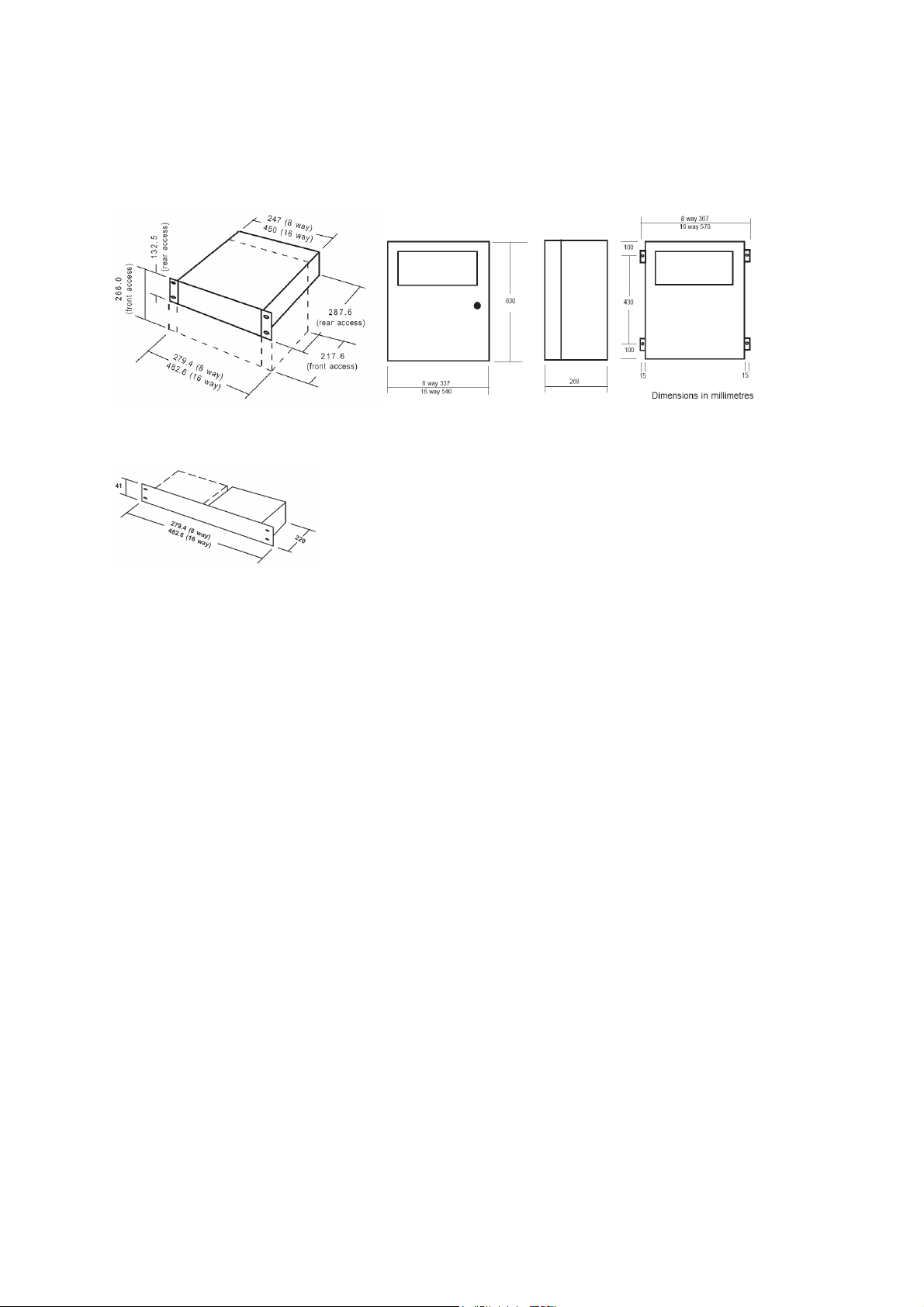
5 Cabinet and Rack Installation
Rear and front access racks outline dimensions
Cabinet outline dimensions
Power supply outline dimensions
6 Detector Installation
Always install the detectors in accordance with the Detector Operating Instructions. In
general, detectors for lighter than air gasses should be located at a high level and detectors
for heavier than air gasses should be located at a low level.
Do not install the detectors:
a. Where the normal air flow may be impeded.
b. In corners of rooms where static air pockets may exist.
c. Near sources of heat such as convector heaters.
Do install the detectors:
a. As close as possible to the potential source of gas to be detected in order to give the
maximum possible warning.
b. So that they are accessible for maintenance work.
7
Page 9
System 57 Quick Start Guide 05701-M-5026 MAN0839 Issue 1
7 Interface Card Connections
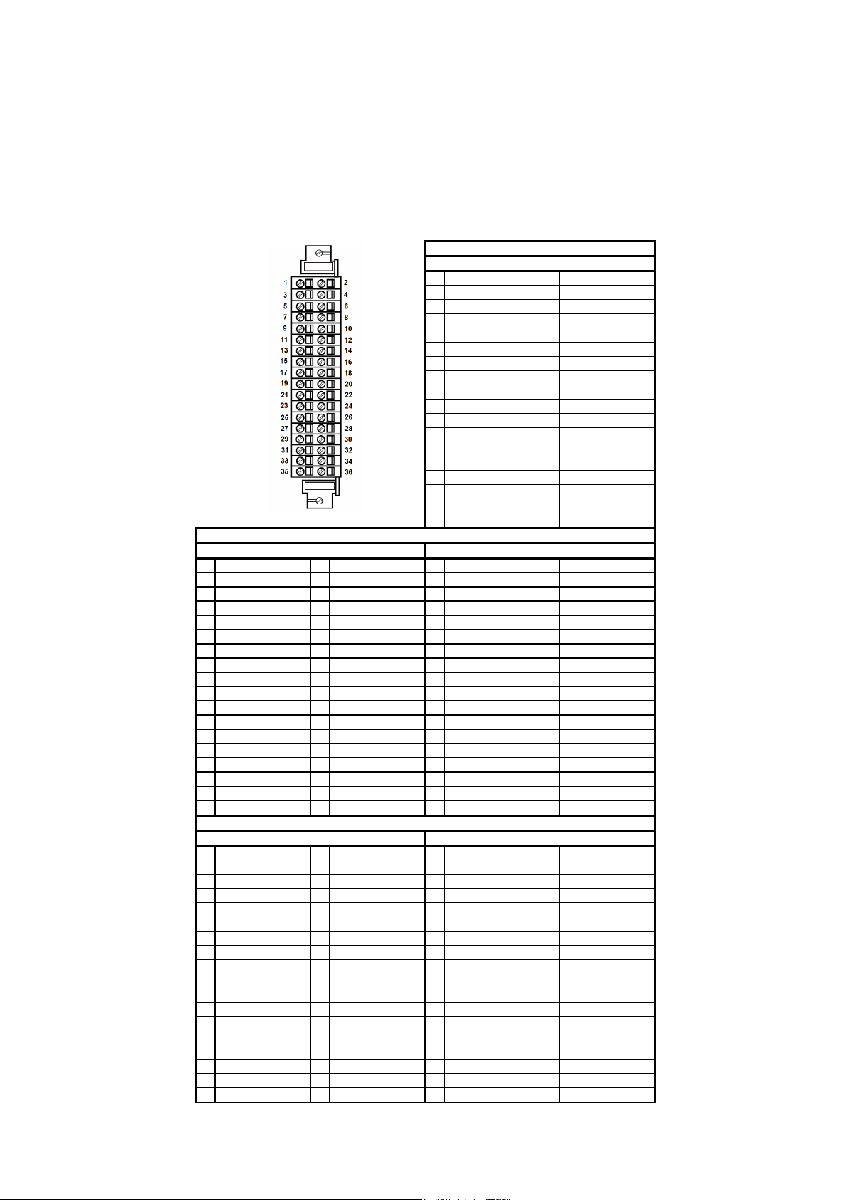
System 57 interface cards use a common card with differing numbers of terminal blocks
fitted according to which type of card it is. The picture below illustrates a card with the
maximum number of terminals fitted. The tables show the terminal connections for 5701,
5704 gas and 5704 fire interface cards.
Interface Relay Card Terminals
1Fault NC 2Fault NO
3 Fault COM 4 Inhibit COM
5 Inhibit NC 6 Inhibit NO
7 A1(1) NC 8 A1(1) NO
9 A1(1) COM 10 A2(1) COM
11 A2(1) NC 12 A2(1) NO
13 A3(1) NC 14 A3(1) NO
15 A3(1) COM 16 A1(2) COM
17 A1(2) NC 18 A1(2) NO
19 A2(2) NC 20 A2(2) NO
21 A2(2) COM 22 A3(2) COM
23 A3(2) NC 24 A3(2) NO
25 Ground 26 Ground
27 Sensor S 28 Sensor 01
29 Sensor NS 30 Not Connected
31 Analogue O/P(+) 32 Analogue O/P (-)
33 Remote Inhibit In 34 Remote Reset In
35 +24V (Out/In) 36 0V (Out/In)
5704 Gas
Quad Relay Card Terminals Expansion Relay Card Terminals
1 Relay 1 NC 2 Relay 1 NO 1 Relay 5 NC 2 Relay 5 NO
3 Relay 1 COM 4 Relay 2 COM 3 Relay 5 COM 4 Relay 6 COM
5 Relay 2 NC 6 Relay 2 NO 5 Relay 6 NC 6 Relay 6 NO
7 Relay 3 NC 8 Relay 3 NO 7 Relay 7 NC 8 Relay 7 NO
9 Relay 3 COM 10 Relay 4 COM 9 Relay 7 COM 10 Relay 8 COM
11 Relay 4 NC 12 Relay 4 NO 11 Relay 8 NC 12 Relay 8 NO
13 Ground 14 Ground 13 Relay 9 NC 14 Relay 9 NO
15 Channel 1 (S) 16 Channel 2 (S) 15 Relay 9 COM 16 Relay 10 COM
17 Channel 1 (01) 18 Channel 2 (01) 17 Relay 10 NC 18 Relay 10 NO
19 Channel 1 (NS) 20 Channel 2 (NS) 19 Relay 11 NC 20 Relay 11 NO
21 Channel 3 (S) 22 Channel 4 (S) 21 Relay 11 COM 22 Relay 12 COM
23 Channel 3 (01) 24 Channel 4 (01) 23 Relay 12 NC 24 Relay 12 NO
25 Channel 3 (NS) 26 Channel 4 (NS) 25 Relay 13 NO 26 Relay 13 COM
27 Analogue 24V 28 Analogue 0V 27 Relay 14 NO 28 Relay 14 COM
29 Analogue CH1 30 Analogue CH2 29 Relay 15 NO 30 Relay 15 COM
31 Analogue CH3 32 Analogue CH4 31 Relay 16 NO 32 Relay 16 COM
33 Remote Reset 34 Remote Inhibit 33 Ground 34 Ground
35 +24V (In) 36 0V (In) 35 Not Used 36 Not Used
5704 Fire
Hex Relay Card Terminals Relay Interface Card Terminals
1 Relay 1 NC 2 Relay 1 NO 1 Relay 5 NC 2 Relay 5 NO
3 Relay 1 COM 4 Relay 2 COM 3 Relay 5 COM 4 Relay 6 COM
5 Relay 2 NC 6 Relay 2 NO 5 Relay 6 NC 6 Relay 6 NO
7 Relay 3 NC 8 Relay 3 NO 7 Relay 7 NC 8 Relay 7 NO
9 Relay 3 COM 10 Relay 4 COM 9 Relay 7 COM 10 Relay 8 COM
11 Relay 4 NC 12 Relay 4 NO 11 Relay 8 NC 12 Relay 8 NO
13 Relay 5 NC 14 Relay 5 NO 13 Relay 9 NC 14 Relay 9 NO
15 Relay 5 COM 16 Relay 6 COM 15 Relay 9 COM 16 Relay 10 COM
17 Relay 6 NC 18 Relay 6 NO 17 Relay 10 NC 18 Relay 10 NO
19 Ground 20 Ground 19 Relay 11 NC 20 Relay 11 NO
21 Input CH1 (+) 22 Input CH2 (+) 21 Relay 11 COM 22 Relay 12 COM
23 Input CH1 (-) 24 Input CH2 (-) 23 Relay 12 NC 24 Relay 12 NO
25 Output CH1 (+) 26 Output CH1 (-) 25 Relay 13 NO 26 Relay 13 COM
27 Input CH3 (+) 28 Input CH4 (+) 27 Relay 14 NO 28 Relay 14 COM
29 Input CH3 (-) 30 Input CH4 (-) 29 Relay 15 NO 30 Relay 15 COM
31 Output CH2 (+) 32 Output CH2 (-) 31 Relay 16 NO 32 Relay 16 COM
33 Remote Input (+) 34 Remote Input (-) 33 Ground 34 Ground
35 +24V (Out/In) 36 0V (Out/In) 35 Not Used 36 Not Used
5701 Gas
8
Page 10
System 57 Quick Start Guide 05701-M-5026 MAN0839 Issue 1
8 Detector Connections
The following sections show generic installation schematics for the most common types of
fire or gas detector and System 57.
8.1 Cable Earthing/Grounding
The detector cable screen or steel wire armour (or braid), as appropriate, should be
connected to the system (protective) earth. This can be achieved where the cable enters the
cabinet by using a metal cable gland, or by other suitable means, and avoiding any screen
'tails' within the cabinet.
Where the cable consists of a separate screen sheath and wire armour (or braid), the
armour should be connected, at the cabinet entry, to the protective earth and the screen
sheath should be connected to the GROUND terminal of the Field Interface/Relay Card or to
a suitable instrument earth point.
Note: Where a detector is earthed locally, either to the Earth Stud or through the detector
casing or mounting, to avoid earth loops the screen sheath of the cable should only be
connected at one end, i.e., at the detector or at the Interface/Relay Card.
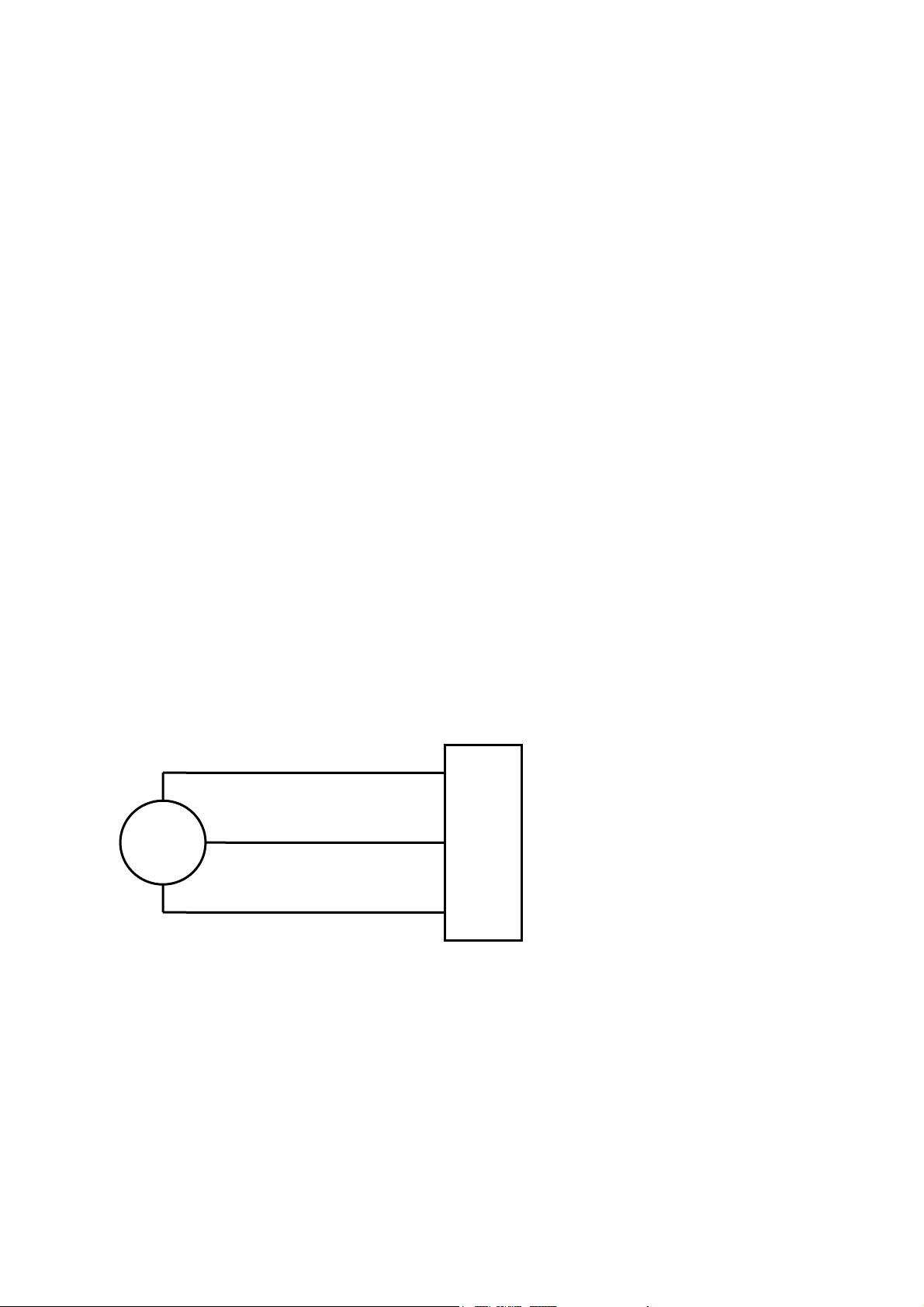
8.2 5701 Gas Card and Catalytic Type Detector
Catalytic detectors require a three wire connection and the detector documentation will
indicate three connections S, 01 and NS, which are usually brown, white and blue
respectively. At the System 57 end of the field cable, the three detector wires should each be
connected to the respective matching S, 01 or NS terminal on the Field Interface or Relay
Card that is attached to the required Single Channel Display Card.
S
01
NS
Detector
27
S
28
01
29
NS
5701 Interface Card
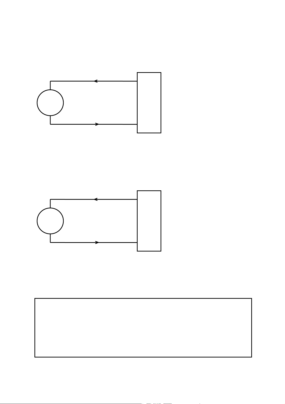
8.3 5701 Gas Card and 2 Wire Loop Powered Detectors
Loop powered detectors require a two wire connection and the detector documentation will
indicate the positive and negative loop connections, usually brown and blue respectively.
At the System 57 end of the field cable the two detector wires should each be connected to
one of either the S, 01 or NS terminals on the Field Interface or Relay Card that is attached
to the required Single Channel Display Card. The two terminals used will vary depending
upon whether the location of the measuring resistance is in the loop supply or return paths.
9
Page 11
System 57 Quick Start Guide 05701-M-5026 MAN0839 Issue 1
8.3.1 4-20mA loop powered detector (measuring resistor in supply
return)
27
+
S
Sensor Drive Module
Link Positions 13, 10
& 4.
-
Detector
28
01
5701 Interface Card
8.3.2 4-20mA loop powered detector (measuring resistor in supply
positive line)
28
+
-
01
Sensor Drive
Module Link
Positions 9, 6 & 1.
29
NS
Detector
5701 Interface Card
8.4 5701 Gas Card and 3 Wire 4-20mA Transmitter
CAUTION
The power provided by the Single Channel Control Card is derived from the dc
input to the System 57 (18V to 32V). Check that the transmitter to be connected is
compatible with the actual supply voltage used.
The maximum current that may be sourced from the field terminals of an individual
Single Channel Control Card to power a field device is 500mA, however, the total
current sourced from all the channels should not exceed the maximum backplane
load current of 8A.
10
Page 12
System 57 Quick Start Guide 05701-M-5026 MAN0839 Issue 1
Transmitters powered from the 5701 Control Card require either three or four wire
connections and the detector documentation will indicate the 0V and +24V power
connections and the positive and negative loop connections.
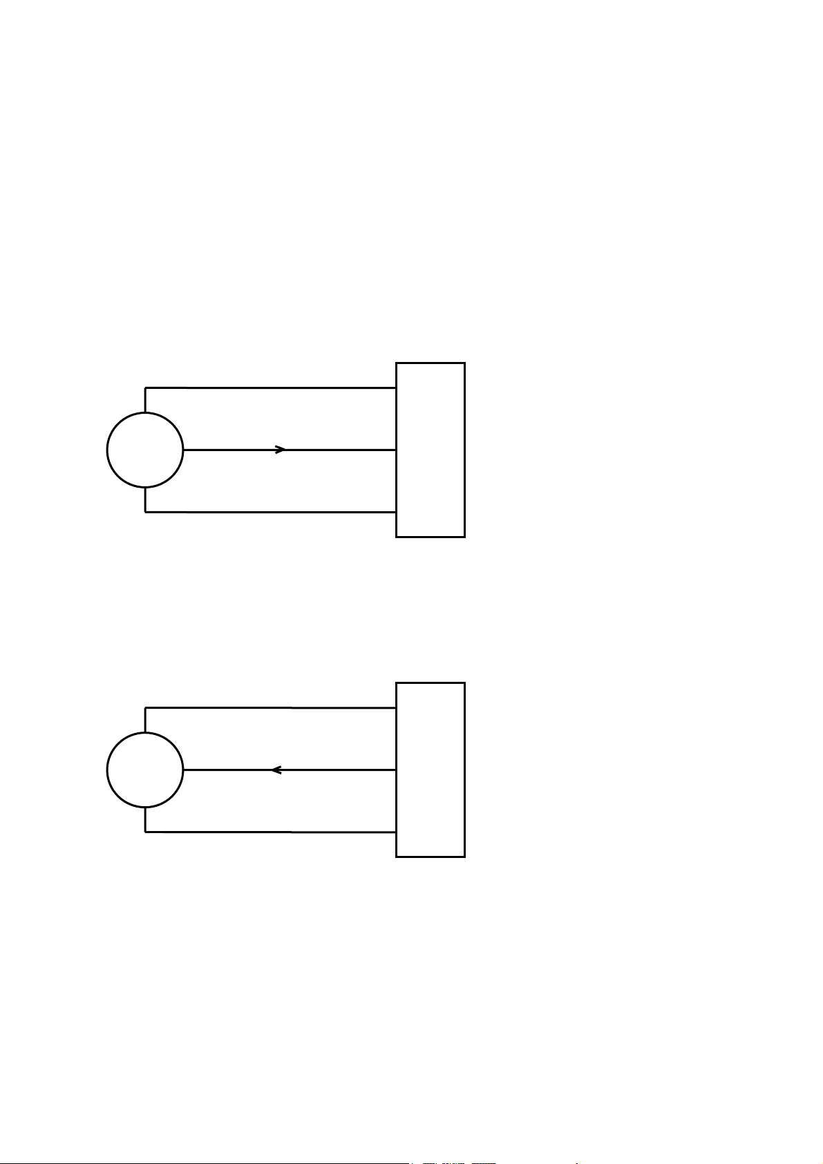
At the System 57 end of the field cable the detector wires should be connected to the S, 01,
NS, 0V or 24V terminals on the Field Interface or Relay Card that is attached to the required
Single Channel Display Card. The exact terminals used vary depending upon whether three
or four wire topology is used, and the requirement for loop current source or sink
configuration. The Schematics below detail the connections for 3 wire current sink or source
transmitters. For other schematics (including isolated and barrier) refer to operating manual
05701-M-5001.
8.4.1 3 Wire Source Transmitter (sink card)
+24V
4-20mA
0V
Transmitter
27
S
28
01
29
NS
5701 Interface Card
8.4.2 3 Wire Sink Transmitter (source card)
+24V
4-20mA
27
S
28
01
Sensor Drive
Module Link
Positions 12, 10,
7 & 3
Sensor Drive
Module Link
Positions 12, 9,
6, 3 & 1.
0V
Transmitter
29
NS
5701 Interface Card
11
Page 13
System 57 Quick Start Guide 05701-M-5026 MAN0839 Issue 1
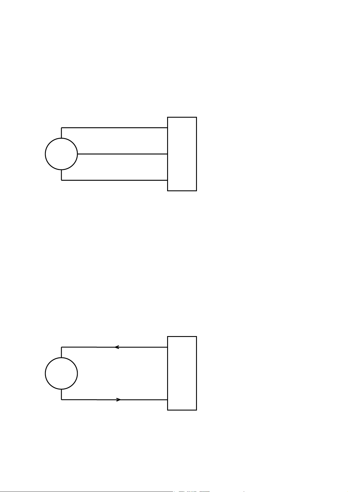
8.5 5704 Gas Card and Catalytic Type Detector
Catalytic detectors require a three wire connection and the detector documentation will
indicate three connections S, 01 and NS, which are usually brown, white and blue
respectively. At the System 57 end of the field cable, the three detector wires should each be
connected to the respective matching S, 01 or NS terminal of the appropriate channel on the
Quad Relay Interface Card that is attached to the required Four Channel Control Card.
S
01
NS
Detector
The diagram shows the detector connections for Channel 1. Channel 2, 3 and 4 connections
are similar and their terminal connection numbers are shown in section 7.
15
S
17
01
19
NS
5704 Quad Card
8.6 5704 Gas Card and 2 Wire Loop Powered Detectors
Loop powered detectors require a two wire connection and the documentation will indicate
the positive and negative loop connections, usually brown and blue respectively.
At the System 57 end of the field cable the two detector wires should be connected to the S
(positive) and 01 (negative) terminals of the appropriate channel on the Quad Relay
Interface Card that is attached to the required Four Channel Control Card.
8.6.1 4-20mA loop powered detector (measuring resistor in supply
return)
27
+
-
Detector
The diagram shows the detector connections for Channel 1. Channel 2, 3 and 4 connections
are similar and their terminal connection numbers are shown in section 7.
S
28
01
5704 Quad Card
12
Page 14
System 57 Quick Start Guide 05701-M-5026 MAN0839 Issue 1
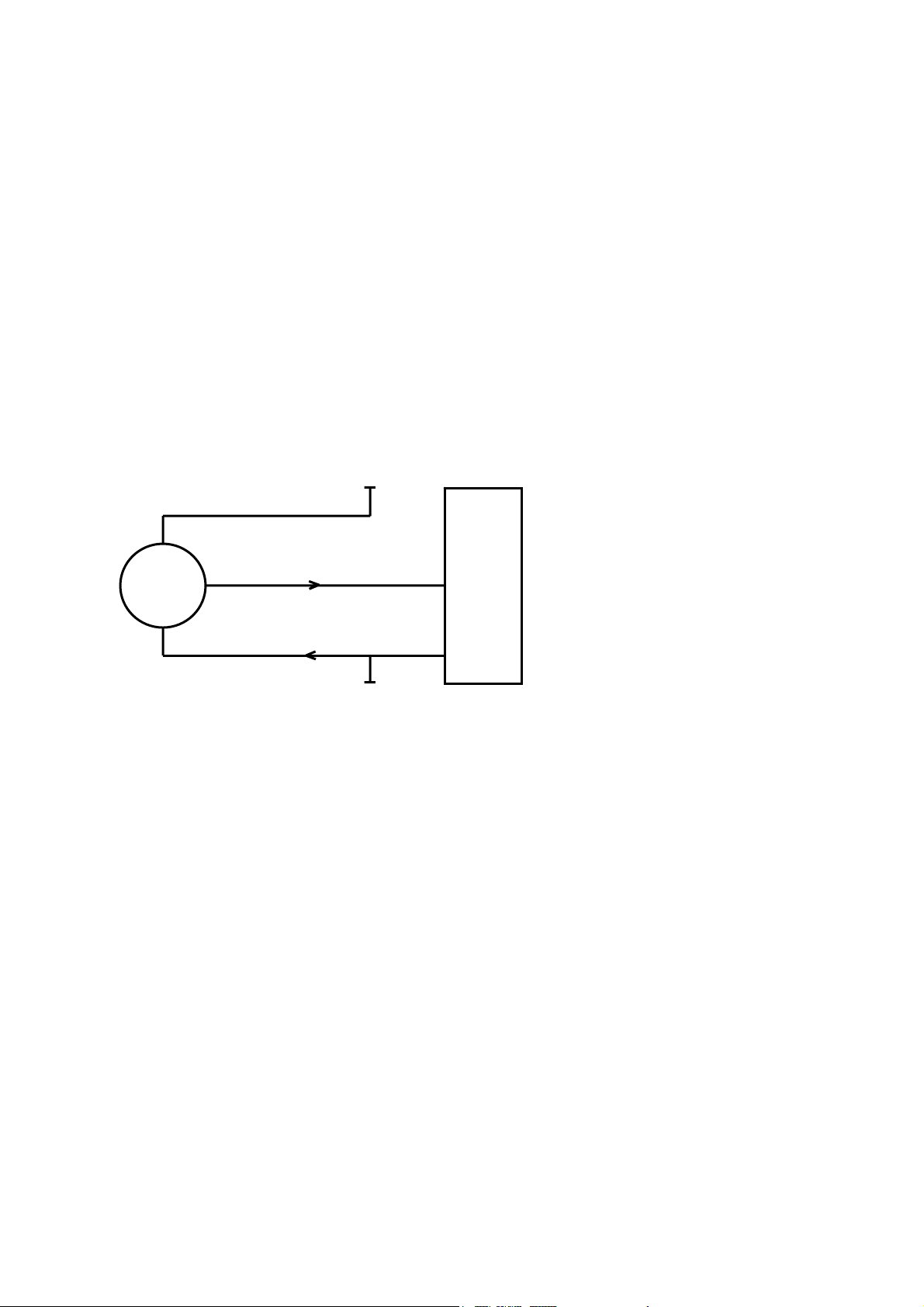
8.7 5704 Gas Card and 3 Wire 4-20mA Transmitter
Transmitters require either three or four wire connections and the dete
will indicate the 0V and +24V power connections and the positive and negative loop
connections. At the System 57 end of the field cable the detector loop signal wires sh
connected to the S, 01, NS terminals on the Quad Relay Interface Card that is attached to
the required Four Channel Control Card. The exact terminals used vary depending upon
whether three or four wire topology is used, the requirement for a loop current source
configuration and the channel to be connected to. The transmitter power connection +2
and 0V should be connected to a suitable dc supply.
ote: Terminals 35 and 36 on the Relay Interface Card are input terminals only and cannot
N
be used to power the transmitter.
he Schematic below details the connections for 3 wire current source transmitters. For
T
other schematics (including isolated and barrier) refer to operating manual 05704-M-5001
+24V*
+24V
ctor documentation
ould be
4V
.
4-20mA
17
01
*24V supply may be obtained
from either the cabinet or a
separate field supply.
19
NS
0V
Transmitter
The diagram shows the detector connections for Channel 1. Channel 2, 3 and 4 connections
are similar and their terminal connection numbers are shown in section 7.
0V*
5704 Quad Card
13
Page 15
System 57 Quick Start Guide 05701-M-5026 MAN0839 Issue 1
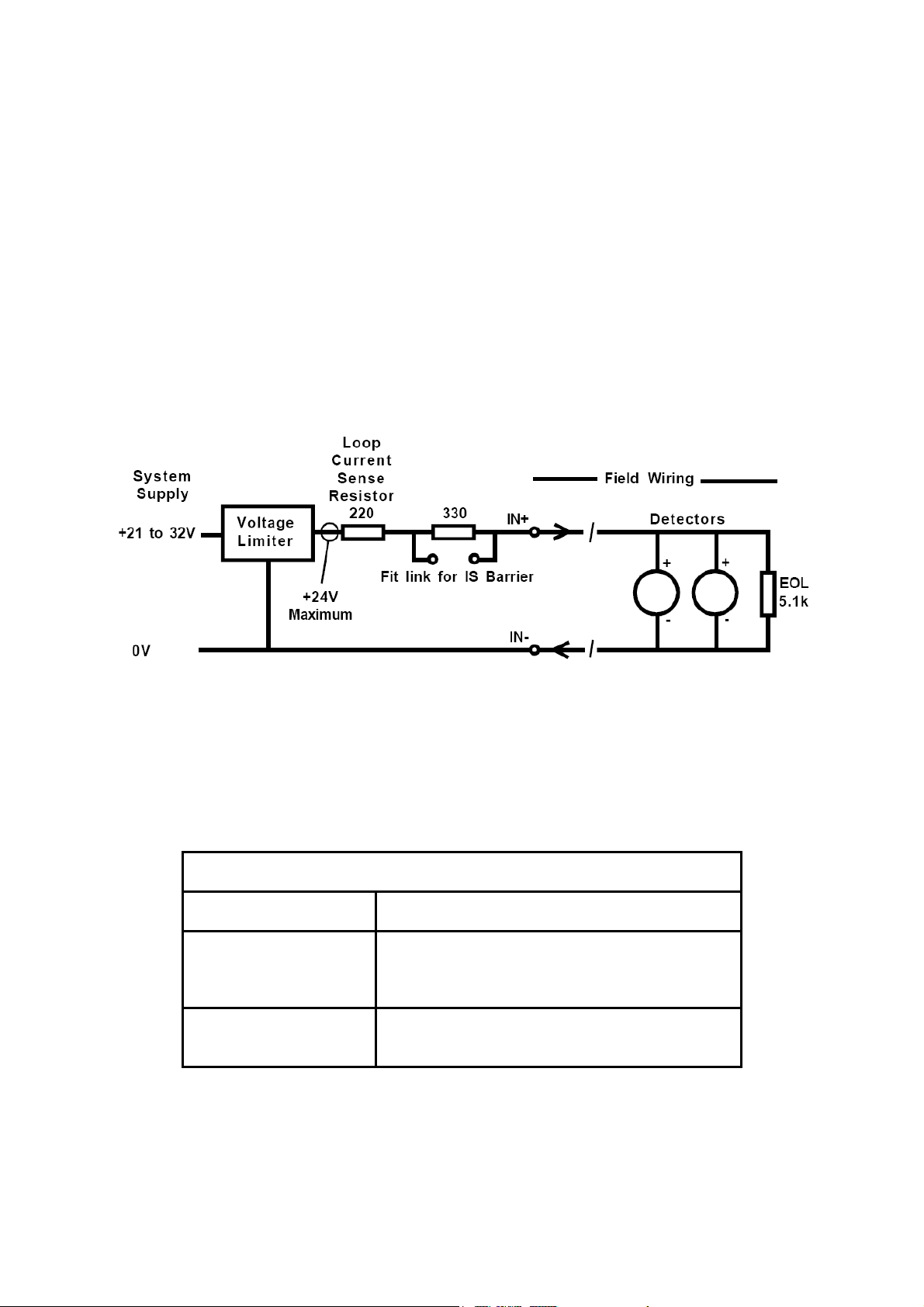
8.8 5704 Fire Card
The 5704F fire input circuit operates from the system dc input supply (21 to 32V) but has a
built-in voltage limiter that limits the maximum loop voltage to +24V to protect the detectors
from damage. When the system supply is less than +24V the limiter has no effect and the
loop will see the true input supply voltage. The loop current is determined by measuring the
voltage across a 220 ohm current sense resistance. A link selectable 330 ohm barrier
equivalent resistance is incorporated for use when an external IS barrier is NOT fitted. For
fault monitoring purposes, an end of line (EOL) resistor must be fitted in or after the last
detector on the loop. The typical value for the end of line resistance is 5.1k ohms although
this may need to be reduced when many detectors are fitted onto the loop.
An equivalent circuit of one fire input together with an example detector connection is shown
below:-
8.8.1 Line Resistance
Detectors should be located such that the line resistance of the cable required does not
prevent correct operation. As a general guide and for a typical installation of twenty low
quiescent current detectors, the loop cable resistance should be kept below 100 ohms total
(50 ohms per core). The table below gives a quick guide to the maximum cable lengths
permitted in this case:
Maximum Cable Length (m)
Detectors Conductor Cross Sectional Area
AWG 21 19 18 16 14
2
mm
20 low quiescent
(100µA) detectors
For further details of line resistance calculation refer to the 5704F Fire Card manual 05704M-5002.
0.50 0.75 1.00 1.50 2.50
1300 2000 2700 4100 6500
14
Page 16
System 57 Quick Start Guide 05701-M-5026 MAN0839 Issue 1
8.8.2 Typical Loop Powered Detector Connections
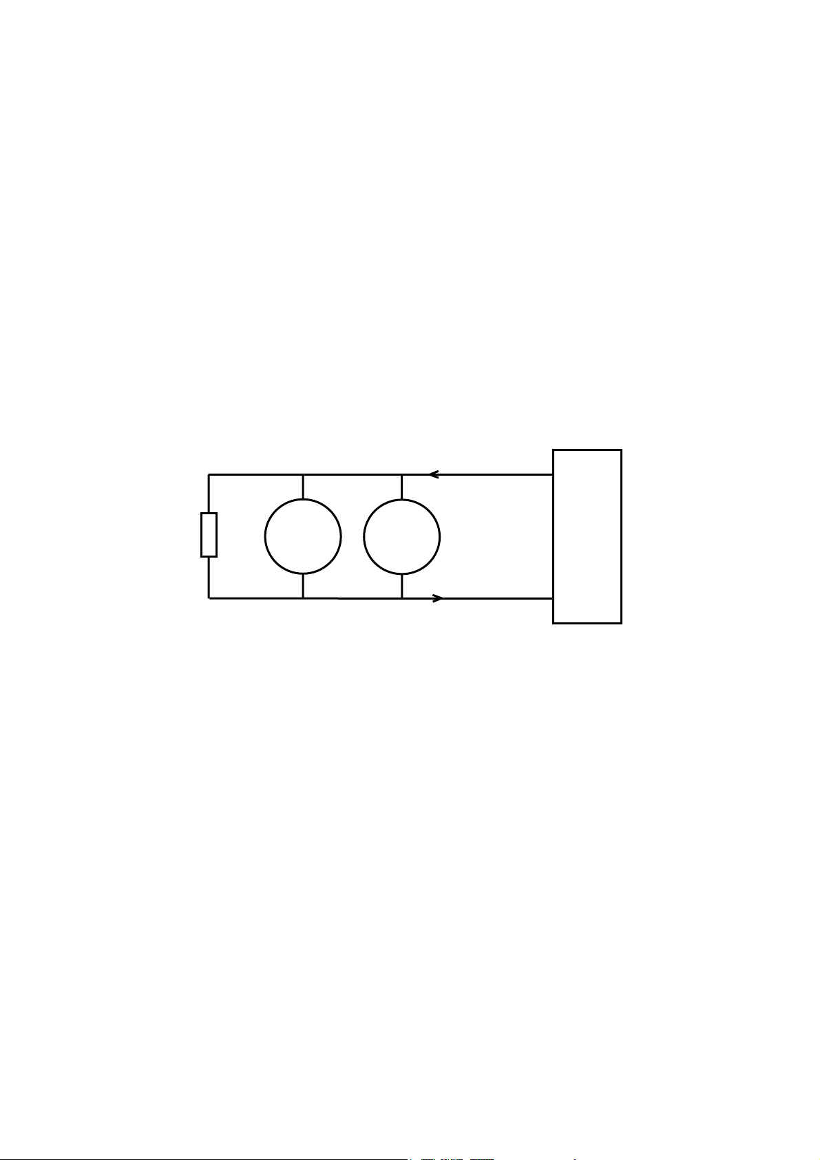
Loop powered detectors (e.g. most smoke, heat and manual call points) have two wire
connection. The detector documentation will indicate the positive and negative loop
connections. Multiple detectors may be connected in parallel on a single loop input provided
the loop operational limit for quiescent current is not exceeded.
At the System 57 end of the field cables, the two detector wires should be connected to the
appropriate channels IN+ and IN- terminals of the Hex Relay Interface Card that is attached
to the required 5704F Control Card. The loop current always flows from the IN+ terminal and
returns via the IN- terminal.
For fault monitoring purposes an end of line (EOL) resistor must be fitted in or after the last
detector on the loop. The typical value for end of line resistance is 5.1k ohms.
The detector cable screen, or steel wire armour or braid as appropriate, should be
connected to the system protective earth. This can be achieved where the cable enters the
cabinet by using a metal cable gland, or by other suitable means, and avoiding any screen
tails within the cabinet. Where the cable consists of a separate screen sheath and wire
armour or braid, the armour should be connected at the cabinet entry to the protective earth
and the screen sheath should be connected to the GROUND terminal of the Hex Relay
Interface Card or to a suitable instrument earth point.
21
+
EOL
5.1k
-
Detectors
The diagram shows the detector connections for Channel 1. Channel 2, 3 and 4 connections
are similar and their terminal connection numbers are shown in section 7.
+
-
IN+
23
IN-
5704 Hex Card
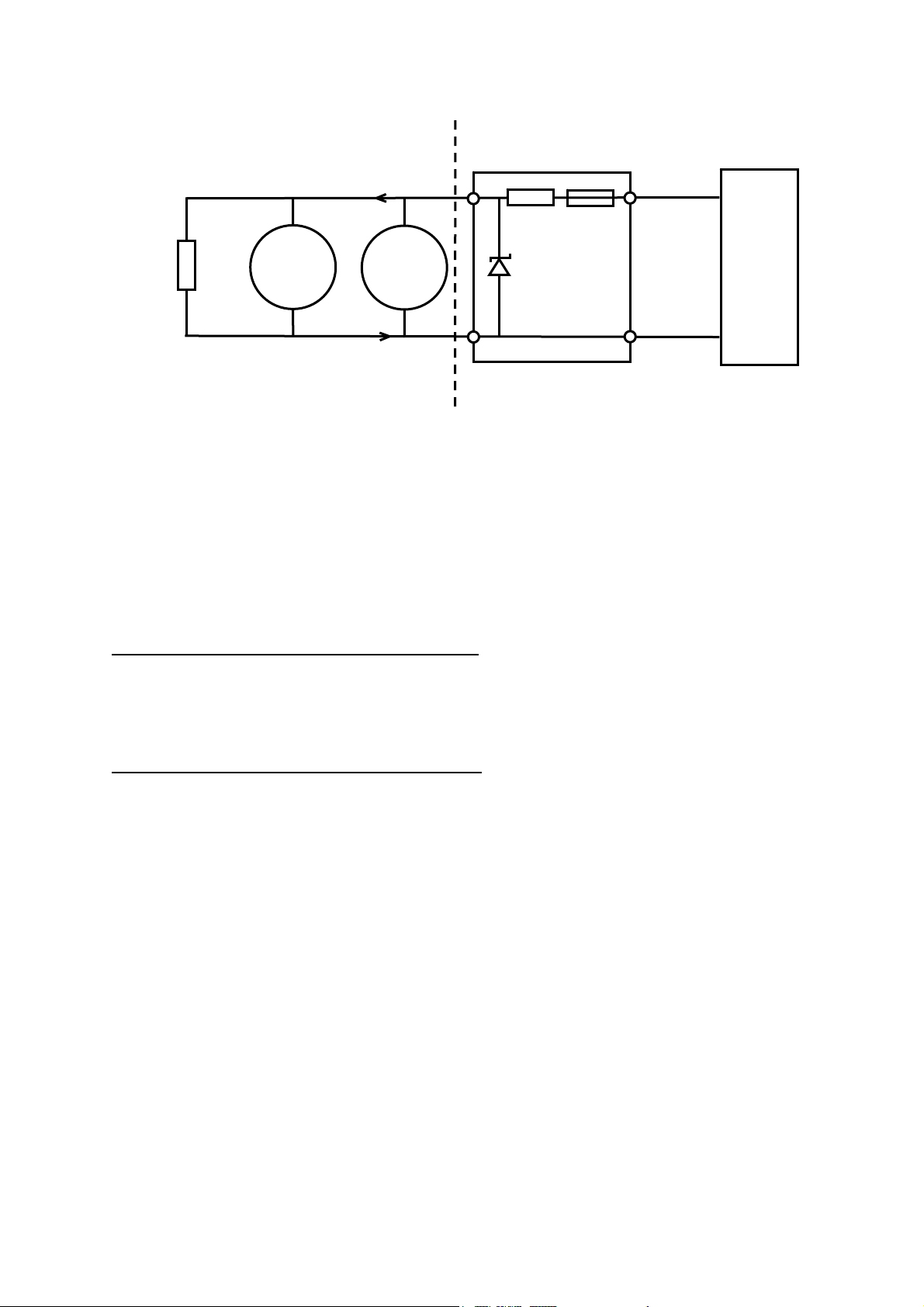
8.8.3 Typical Loop Powered Detector with IS Barrier Connections
Loop powered intrinsically safe detectors (e.g. most smoke, heat and manual call points)
have two wire connection. The detector documentation will indicate the positive and negative
loop connections. Multiple detectors may be connected in parallel on a single loop input
provided the IS criteria and loop operational limit for quiescent current are not exceeded.
In the safe area, the two wires from the detector should be connected to the field (hazardous
area) side of the barrier. The input (safe area) side wires from the barrier should be
connected to the appropriate channels IN+ and IN- terminals of the Hex Relay Interface
Card that is attached to the required 5704F Control Card. The loop current always flows from
the IN+ terminal and returns via the IN- terminal. The barrier must be earthed appropriately.
For fault monitoring purposes an end of line (EOL) resistor must be fitted in or after the last
detector on the loop. The typical value for end of line resistance is 5.1k ohms.
When using an external barrier the IS compatibility link for the input must be set
appropriately. Intrinsically safe systems must be earthed at one point only. All detector cable
screens should be connected separately to the IS safety ground.
15
Page 17
System 57 Quick Start Guide 05701-M-5026 MAN0839 Issue 1
Hazardous Area
+
EOL
5.1k
-
Detectors
The diagram shows the detector connections for Channel 1. Channel 2, 3 and 4 connections
are similar and their terminal connection numbers are shown in section 7.
Notes: 1. Earth Leakage must not be used with single or dual barriers since the 0V is
connected to IS ground. If earth leakage is required an isolating barrier must be used.
2. A suitable barrier specification is a 28V 300 ohm Shunt Barrier with 50mA minimum
current capability for short circuit survival.
Fire Card Link Settings:
LK150- Earth Leakage Fault Detection Enable.
Default position 1 to 2 to disable detection. Link 2 to 3 to enable the earth leakage detection
circuit. IMPORTANT: This link should be set on one fire card only and usually the card
connected to the Fire Status Panel.
LK101, 201, 301, 401- I.S. Input Compatibility.
Individual setting for inputs 1 to 4 respectively. Default position 1 to 2 for normal operation.
Link 2 to 3 when using an external I.S. barrier.
+
-
Safe Area
21
IN+
Fuse
x 3
23
IN-
Safety Barrier
e.g. MTL 728
5704 Hex Card
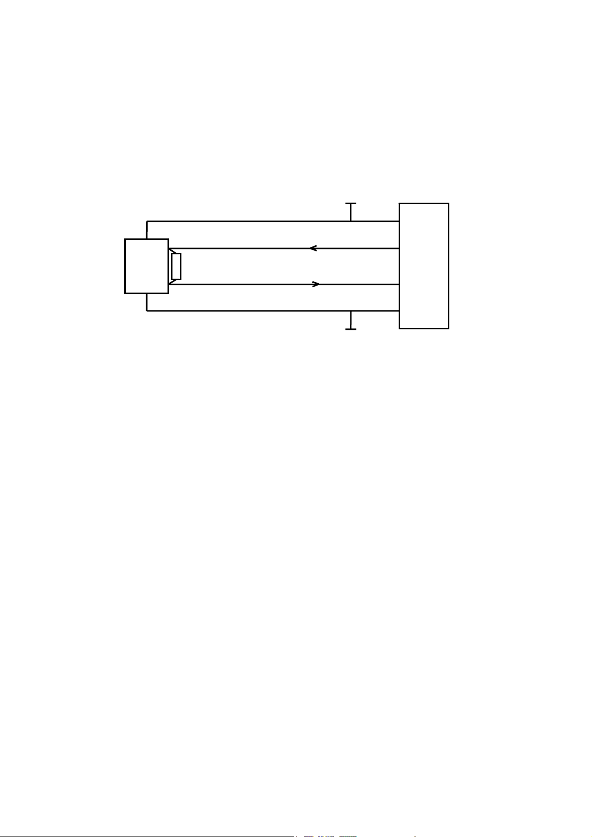
8.8.4 Separately Powered Detectors
Separately powered detectors (e.g. most IR, UV/IR Flame detectors) require three or four
wire connections. The detector documentation will indicate the 0V and +24V power
connections and the positive and negative loop connections. When using flame detectors it
is common practice to use only one detector per loop input.
At the System 57 end of the field cables the two detector signal wires should be connected
to the appropriate channels IN+ and IN- terminals of the Hex Relay Interface Card that is
attached to the required 5704F Control Card. The loop current always flows from the IN+
terminal and returns via the IN- terminal.
The power for the detector may be sourced from the System 57 power supply or a separate
field supply, whichever is most appropriate. In small systems, power can be obtained from
terminals 35 and 36 of the Hex Relay Interface Card, but care must be taken not to exceed
the maximum backplane current loading of 8A. A separate dc power distribution block is
recommended.
For fault monitoring purposes, an end of line (EOL) resistor must be fitted in or after the last
detector on the loop. The typical value for end of line resistance is 5.1k ohms.
16
Page 18
System 57 Quick Start Guide 05701-M-5026 MAN0839 Issue 1
The detector cable screen, or steel wire armour or braid as appropriate, should be
connected to the system protective earth. This can be achieved where the cabl
cabinet by using a metal cable gland, or by other suitable means, and avoiding any
e enters the
screen
tails within the cabinet.
Where the cable consists of a separate screen sheath and wire armour or braid, the armour
should be connected at
the cabinet entry to the protective earth and the screen sheath
should be connected to the GROUND terminal of the Hex Relay Interface Card or to a
suitable instrument earth point.
+24V*
35
+24V*
24V
UV/IR
Flame
0V
EOL
5.1k
21
IN+
23
IN-
36
0V
Flame Detector
0V*
5704 Hex Card
The di etector connections for Channel 1. Channel 2, 3 and 4 connect
agram shows the d ions
are similar and their te
rminal connection numbers are shown in section 7.
N
otes: 1. Separate provision may be required for power supply isolation in order to reset the
d
etector after an alarm condition. Consult the detector operating instructions for more
details.
2. For a 3 wire connection, the IN- signal can return via the 0V supply but care should be
taken wi
th the system layout to minimise electrical noise and other forms of interference.
3. Where a detector is earthed locally, either to an Earth Stud or through the sensor casing
or mounting, to avoid earth loops the screen sheath of the cable should be connected at o
end only.
ne
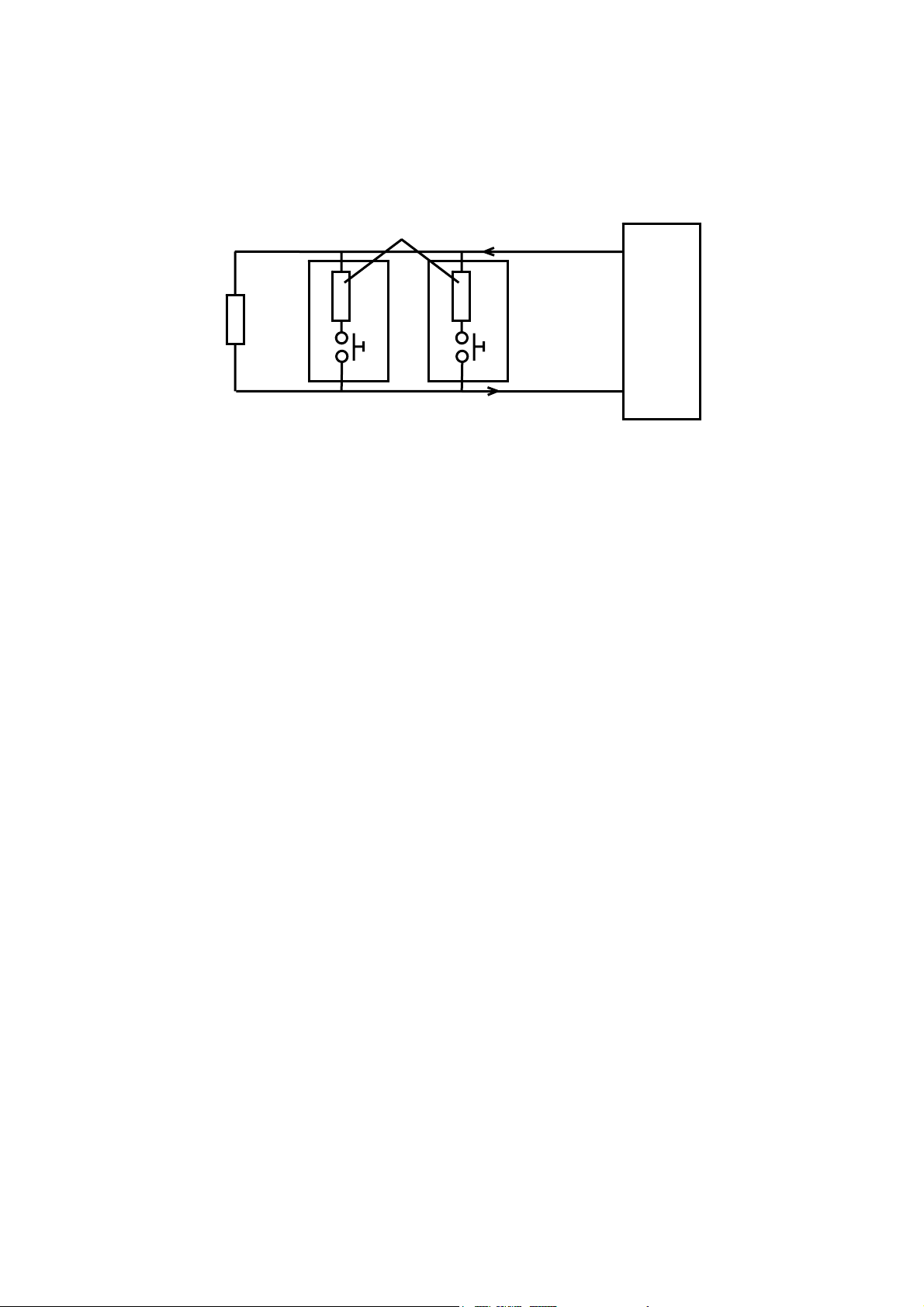
.8.5 Call Points and Simple Switched Output Detectors
8
Manually Activated Call Points (MAC) and some fire detectors have a simple switch
output via two wire connection. The detector documentation will indicate
the switch contact
ed alarm
connections. Many call points may be connected in parallel on a single loop input, but it is
good practice to keep call points on a separate input to other types of detector.
At the System 57 end of the field cables the two call point signal wires should be connected
to the appropriate channels IN+ and IN- terminals of the Hex Relay Interface Ca
rd that is
attached to the required 5704F Control Card. The loop current always flows from the IN+
terminal and returns via the IN- terminal.
For fault monitoring purposes an end of line (EOL) resistor must be fitted in or after the las
call point on the loop. The typical value fo
r end of line resistance is 5.1k ohms.
The detector cable screen, steel wire armour or braid as appropriate, should be connected t
the system protective earth. This can be achieved where the cable enters the ca
binet by
using a metal cable gland, or by other suitable means, and avoiding any screen tails within
the cabinet.
17
t
o
Page 19
System 57 Quick Start Guide 05701-M-5026 MAN0839 Issue 1
Where the cable consists of a separate screen sheath and wire armour or braid, the armour
should be co nnected at the cabinet entry to the protective earth and the screen sheath
should be connected to the GROUND terminal of the Hex Relay Interface Card or to a
suitable instrument earth point.
Alarm Current Resistor
21
IN+
620
620
EOL
5.1k
23
IN-
Manual Call Points
5704 Hex Card
The diagram shows the detect annel 1. Channel 2, 3 and 4 connec
are similar and their te
rminal connection numbers are shown in section 7.
or connections for Ch tions
Notes: 1. Most modern call points already incorporate the alarm current re
typical value of 620 ohms, if not this can be easily fitted externally within the call point
a
sistor, shown with
junction box.
2. The Fire Card inputs are also compatible with devices that use a zener diode, typical
value 8.2V, 0.
5W, to set the alarm current.
3. The operation of more than two call points simultaneously may cause the loop current
exceed the short circuit warning threshold. T
his will not suppress the alarm output but a fault
indication will be given on the fire card display.
4. Where the call point is earthed locally, either to an Earth Stud or through the sensor
casing or mounting, the screen sheath of the ca
ble should be connected at one end only to
avoid earth loops.
to
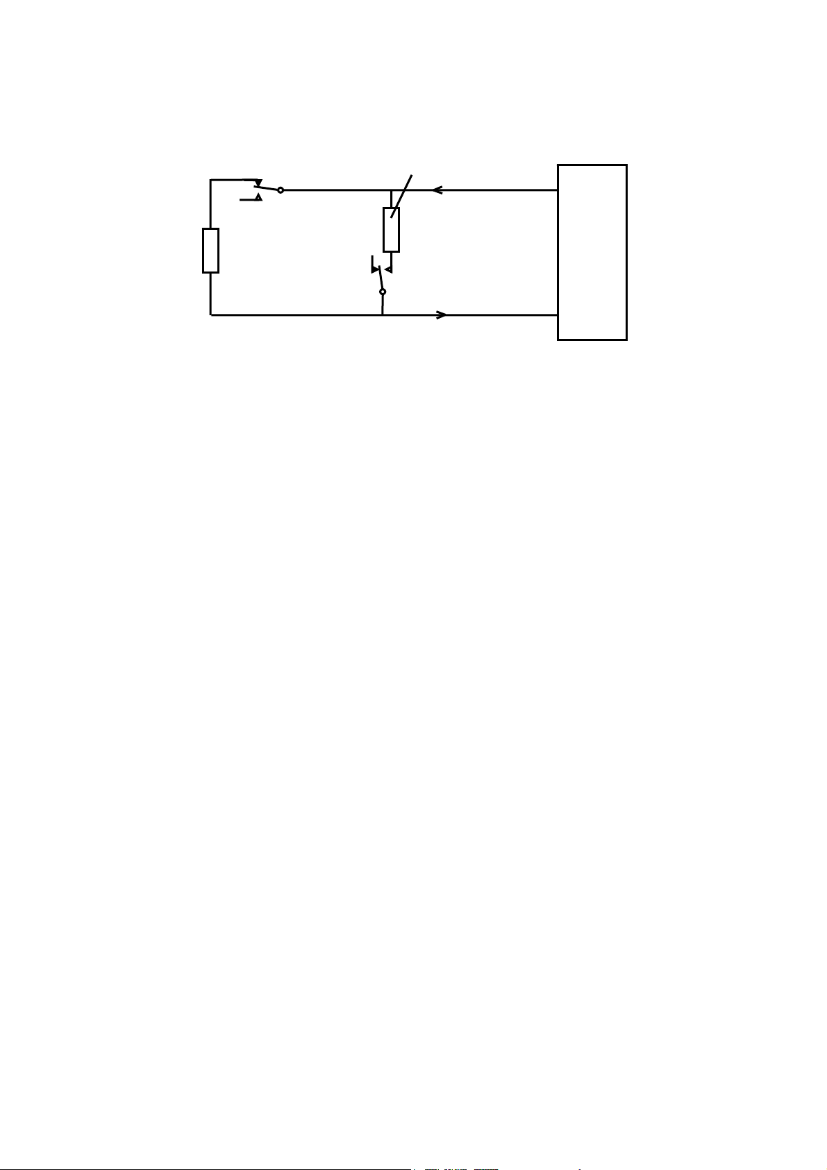
.8.6 Detectors with Voltage Free Contact Outputs
8
Some fire detectors (especially flame) are equipped with a voltage free contact for th
output and often with a second voltage free contact for fault outpu
t. These types of detector
e alarm
are easily connected to the fire card using a two wire connection. The detector
documentation will indicate the voltage free contact connections. Although a number of
detectors may be connected in parallel on a single loop input, it is good practice
to connect
only one flame detector on any input.
At the System 57 end of the field cables the signal wires should be connected to the
appropriate channels IN+ and IN- term
inals of the Hex Relay Interface Card that is attached
to the required 5704F Control Card.
The loop current always flows from the IN+ terminal and returns via the IN- terminal. For
fault monitoring purposes, an end of
line (EOL) resistor must be fitted in or after the last
detector on the loop. The typical value for end of line resistance is 5.1k ohms.
The detector cable screen or steel wire armour or braid as appropriate, should be connec
to the system protective earth. This can be achieved where the cable enters the
cabinet by
ted
using a metal cable gland, or by other suitable means, and avoiding any screen tails within
the cabinet.
Where the cable consists of a separate screen sheath and wire armour or braid, the armour
should be co
nnected at the cabinet entry to the protective earth and the screen sheath
18
Page 20
System 57 Quick Start Guide 05701-M-5026 MAN0839 Issue 1
A
A
should be connected to the GROUND terminal of the Hex Relay Interface Card or to a
suitable instrument earth point.
larm Current Resistor
21
IN+
Normally Closed
Fault Contact
620
EOL
5.1k
Normally Open
larm Contact
23
IN-
Volt Free Output Detector
5704 Hex Card
The diagram shows the detector connections for Channel 1. Channel 2, 3 and 4 connec
are similar and their te
rminal connection numbers are shown in section 7.
tions
Notes: 1. Some detectors may incorporate the alarm current resistor shown with a typical
v
alue of 620 ohms, if not, this can be easily fitted externally within the detector junction box.
2. Where the detector is earthed locally, either to an earth stud or through the detector
casing or mounting, to avoid earth loops the screen sheath of the cable should be connected
at one end only.
19
Page 21
System 57 Quick Start Guide 05701-M-5026 MAN0839 Issue 1
9 Specification
9.1 Approvals and Standards
Designed to comply with:
EN50054 General Requirements (Combustible Gases).
EN50057 Performance (100 LEL).
EN50058 Performance (100 V/V).
EN50271 Software and Digital Technologies.
Meets Exe isolation requirements for 50V operation.
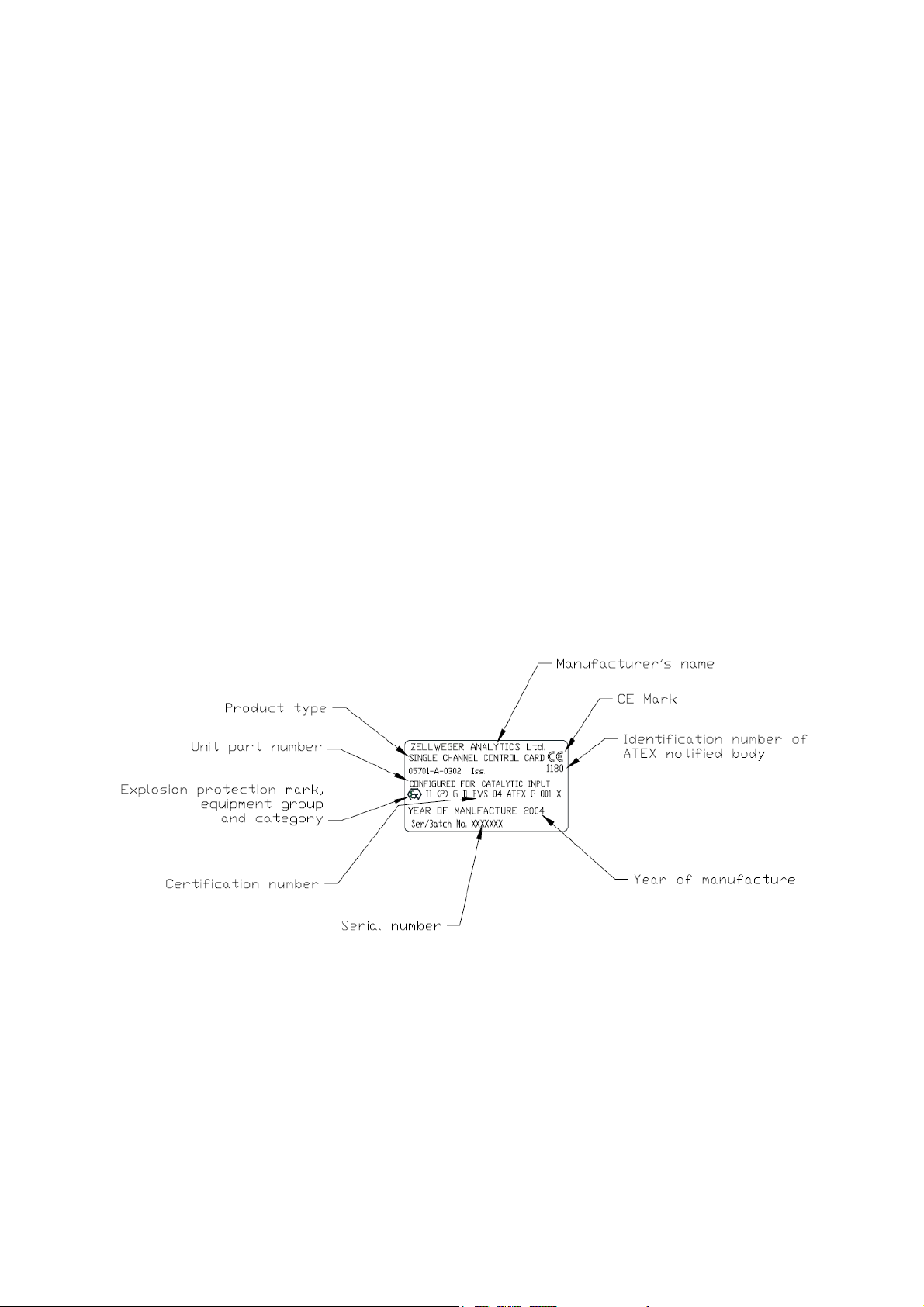
EXAM BBG Pruef- und Zertifizier GmbH, EC-type examination certificate BVS 04 ATEX G
001 X.
Note: If compliance with the EC-type examination certificate BVS 04 ATEX G 001 X is
required, refer to chapter 10 ‘Special Conditions for Safe Use’. Ensure that all conditions
therein are met.
20
Page 22

System 57 Quick Start Guide 05701-M-5026 MAN0839 Issue 1
9.2 Environmental
Operating Temperature: -5
Storage Temperature: -25
Humidity: 0 to 90% RH. Non-condensing.
º
C* to +55ºC (*0° for EXAM approved systems).
º
C to +55ºC.
9.3 RFI/EMC Conformity
EMC Directive 89/336/EEC Conforms to: EN 50270:1999
Special conditions: The optional recorder output may be in error by ±5% fsd during some
test conditions of the industrial standard if the connecting cables are not shielded with an
outer screened cable.
Radiated Susceptibility: 10V/m over 50kHz to 1GHz. Note: The Part 2
conformity refers to installations using the System 57
cabinet. For System 57 racks not supplied in cabinets
or supplied in GRP cabinets, the conformity is to Part 1.
LV Directive 73/23/EEC
Constructed in accordance with good engineering practice. Guided by the principles of
EN61010/1 1990/1992.
21
Page 23

System 57 Quick Start Guide 05701-M-5026 MAN0839 Issue 1
10 Special Conditions For Safe Use.
ACCORDING TO EC-TYPE EXAMINATION CERTIFICATE BVS 04 ATEX G 001 X
The following special properties have to be considered at operation of the control unit:
-
When operated with remote detectors with 4-20mA interface the specifications of the 4-20mA interface and the
behaviour below 4mA and above 20mA have to be considered.
- The parameters “A/D-average” and “signal filter” shall be set to the detector-specific default values. Other
settings shall only be used in exceptional, justified circumstances and with the manufacturer’s permission. For
both parameters, the lowest settings shall be used which are possible for the application.
- When configuring the control cards, the detector specific default settings should be used for the error codes
“ER80”, “ER81”, “ER87” and “ER88” (parameters “signal over range”, “signal under range”, “fault over range”
and “fault under range”).
- The error codes “ER87”, “ER88” and “ER81” (parameters “fault over range”, “fault under range” and “signal
under range”) shall be set latching.
- When operated with remote detectors (e.g. Sensepoint) which may deliver signals within the measuring range
at concentrations above the measuring range, the error code “ER80” (parameter “signal over range”) shall be
set latching. If the parameter is set below the default value all alarm relays shall be configured in such a way
that alarming also takes place in the presence of detector faults.
- For remote detectors with 4-20mA interface the parameters “signal over range” and “fault over range” shall be
set in such a way that during normal operation (including the application of 100 % gas to the remote detector)
“ER80” can be activated but not “ER87”.
- The analogue outputs should be operated with live zero (4-20mA setting). The “< 4mA clipping” feature should
be activated only in exceptional cases. Irrespective of the operating mode of the analogue output, the “fault
level” and “inhibit level” shall be configured to different values outside the measuring range. The signaling of
faults and inhibits at the analogue output shall be activated.
- If no local inhibit relays are configured, a master inhibit relay shall be configured.
- If no local fault relays are configured, a master fault relay shall be configured.
- When relays are used for signaling update alarms, no other alarms or messages must be allocated to them.
Configuration of update messages for “inhibit” should be avoided.
- Time delayed relays shall not be used.
- The status of the control unit obtained via Modbus shall be used only for the purpose of visualisation or
documentation but not for safety purposes. Write access via Modbus shall be avoided. This certificate is
concerned solely with information which can be obtained from Modbus functions 02 and 04.
- When a control card 5701 is configured for master or voted alarms as well as master or voted fault or inhibit
messages, high integrity relay cards should be used. If no high integrity relay cards are used, triple relay cards
shall be used. In such cases, both the relays and the LEDs of this control card will reflect only the status of the
master or voting group. For an “X out of Y” linkage with vote counts (X) > 1, local alarms or messages of this
control card are not displayed if less than X control cards have entered the alarm, fault or inhibit status,
respectively. Therefore, voting groups have to be configured in such a way that vote counts of “1” are used for
voted faults and inhibit messages to allow for signaling of local fault and inhibit states of the control card.
- Relay 1 of a high integrity relay card is always assigned to a local fault. It is also used for signaling malfunction
of the high integrity relay card itself. Therefore, this relay shall be monitored for each high integrity relay card.
22
Page 24

Thank you for reading this data sheet.
Please contact us for a quotation:
Head Office (UK)
P.O. Box 2124
Chelmsford
Essex CM1 3UP
England
Tel: +44 (0)1245 600 560
Fax: +44 (0)1245 600 030
Email:
General Information/Sales:
Accounts Department:
USA Office
233 Rogue River Highway #425
Grants Pass
Oregon 97527-5429
USA
Switzerland Office
Zugerstrasse 46
6314 Unterägeri
Zug
Switzerland
Tel: +41 41 541 5877
Fax: +41 41 541 5878
Email:
General Information/Sales:
Accounts Department:
Latin America Office
World Trade Centre
Apartado 0832-00708
Ciudad de Panamá
República de Panamá
Tel: +1 503 206 0941
Fax: +1 541 610 1646
Email:
General Information/Sales:
Accounts Department:
Tel: +507 836 5304
Fax: +507 399 1804
Email:
General Information/Sales:
Accounts Department:
 Loading...