

Page 1
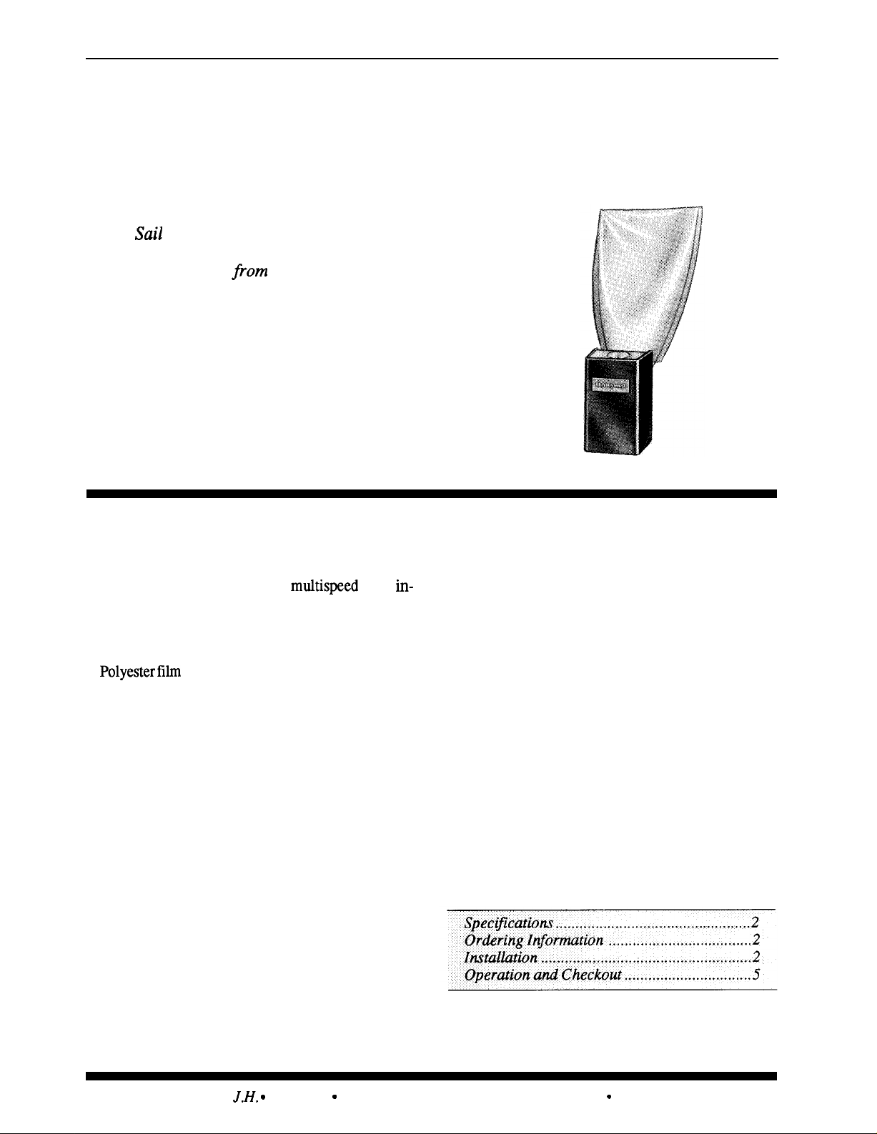
Honeywell
S688A
Sail Switch
The
cleaner, a humidifier, or other equipment in
response to airflow
S688A is rnountedin the return air duct where the
sail will be in the direct path of an unrestricted
air stream.
■
Simplified installations with
accessible air handlers, fan motors with voltage or
phase different from controlled equipment; elimi-
nated wiring to system fan.
■
switch.
Switch activates an electronic air
the system fan. The
fans,
sail mounted on a micro switch snap
■ Top and bottom conduit knockouts for wiring
■ Low air velocity switch operation—makes at
convenience.
250 fpm and breaks at 75 fpm.
■
Removable spring counterbalances sail to allow
mounting in either vertical (up or down) or hori-
zontal air flow.
Rev. 9-91
@Honeywell Inc. 1991 ● Printed in U.S.A.
CONTENTS
Form Number 60-2103-3
Page 2
S688A
SPECIFICATIONS ● INSTALLATION ● ORDERING INFORMATION
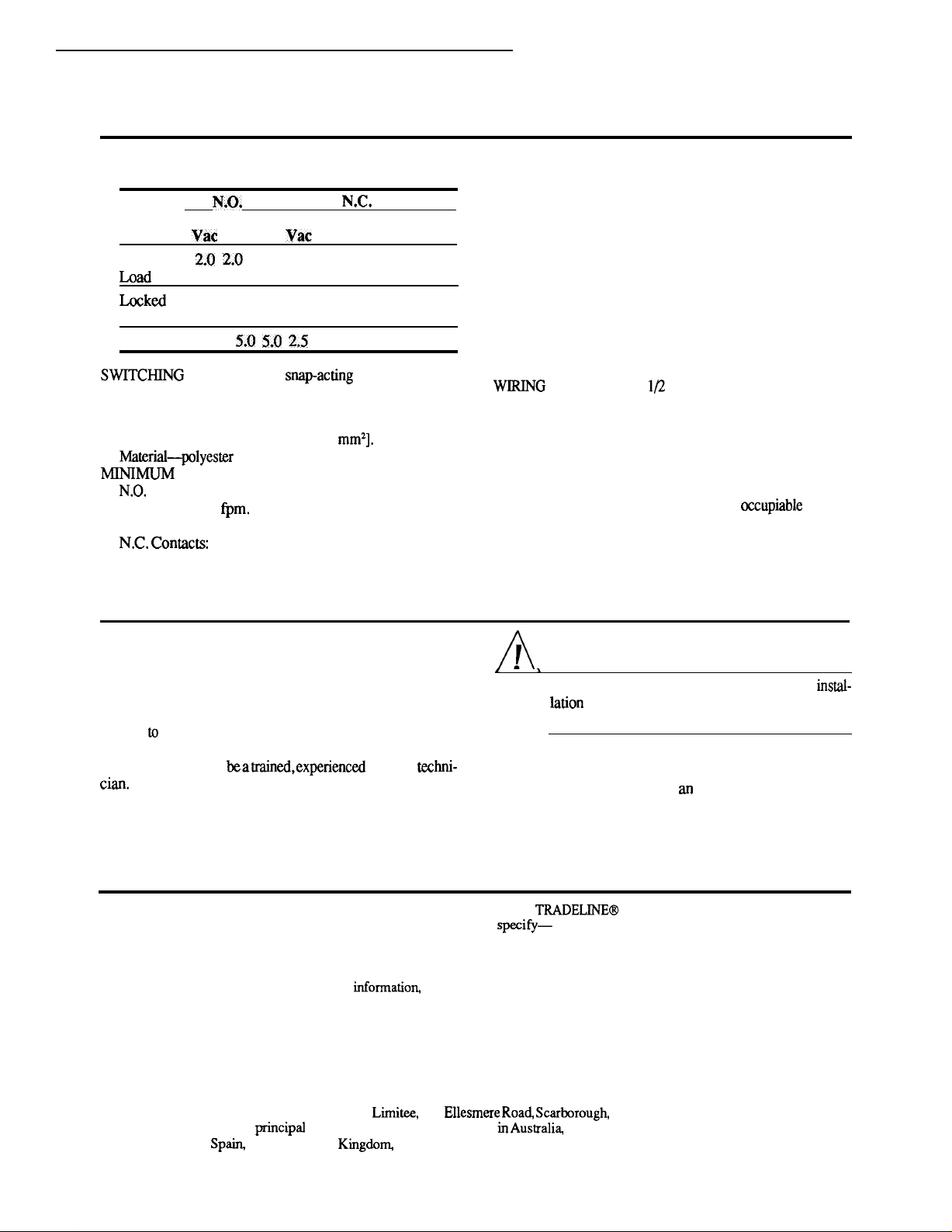
Specifications
MODEL S688A Sail Switch.
ELECTRICAL RATINGS (Amperes):
,,
Contacts
24 120 240
Vac
Full
Rotor
Resistive
SAIL DATA:
Insertion length-10 in. [254 mm].
Maximum width-5 in. [127 mm].
Approximate area-26.2 in.
Contacts:
Makes-250
Breaks-75 fpm.
Makes-75 fpm.
Breaks-250 fpm.
1.0 1.0
12.0 12.0 6.0 6.0 6.0 3.0
ACTION Spdt
film sealed on music wire frame.
AIRFLOW
24 120 240
Vac Vac Vac
2.5 2.5 2.5
2
[1690
Contacts
1.0 0.5
switch.
MAXIMUM AMBIENT TEMPERATURES:
125° F [52° C] at switches.
170° F [77° C] at sail.
CASE DIMENSIONS: 2-5/16 in. [59 mm] high, 3-3/4 in.
[95 mm]
DUCT MOUNTING HOLE DIMENSIONS: 1-1/2 in.
[38 mm] by 2-1/4 in. [57 mm].
MOUNTING MEANS: Switch mounts on return air duct
with two sheet metal screws. An adhesive backed mounting template is provided. Sail is inserted into duct through
1-1/2 in. [38 mm] by 2-1/4 in. [57 mm] hole.
MOUNTJNG POSITION: Mounts in vertical (up or down)
or horizontal airflow.
end of ease.
FINISH: Zinc plated case and cover.
REPLACEMENT PARTS: Part no. 123773A Replacement
wide, 2-1/8 in. [54 mm] deep.
KNOCKOUTS:
in. conduit knockout in either
sail.
UNDERWRITERS’ LABORATORIES, INCL LISTED:
File No. E4436, Guide No. XAPX. For use in ambient
temperatures normally prevailing in
which usually are not higher than 77° F [25° C] but
occasionally may be as high as 104° F [40° C] for brief
periods.
spaces,
Installation
WHEN INSTALLING THIS PRODUCT...
1. Read these instructions carefully. Failure to follow
them could damage the product or cause a hazardous condition.
2. Check the ratings given in the instructions and on the
product
tion.
eration as provided in these instructions.
make sure the product is suitable for your applica-
3. Installer must
4. After installation is complete, check out product op
service
CAUTION
Disconnect power supply before beginning
damage.
LOCATION
Locate the sail switch in the return air duct where the sail
will be in the direct path of
Maximum ambient temperature at the switch is 125°
[52° C] and at the sail is 170° F [77° C]. The air duct at the
Ordering Information
When
purchasing replacement and modernization products from your
TRADELINE Catalog or price sheets for complete ordering number, or specify—
1. Order number, TRADELINE, if desired.
If you have additional questions, need further
1. Your local Honeywell Residential Sales Office (check white pages of phone directory).
2. Residential Division Customer Satisfaction
Honeywell Inc., 1885 Douglas Drive North
Minneapolis, Minnesota 554224386 (612) 542-75(XI
wholesaler
unrestricted air stream.
F
or your distributor, refer to the
In Canada-Honeywell Limited/Honeywell
Service Offices in all
Netherlands,
Taiwan, United Kingdom U.S.A.
2
Ontario M 1P 2V9. International Sales and
Canada, Finland, France, Germany, Japan, Mexico,
Page 3
S688A
INSTALLATION
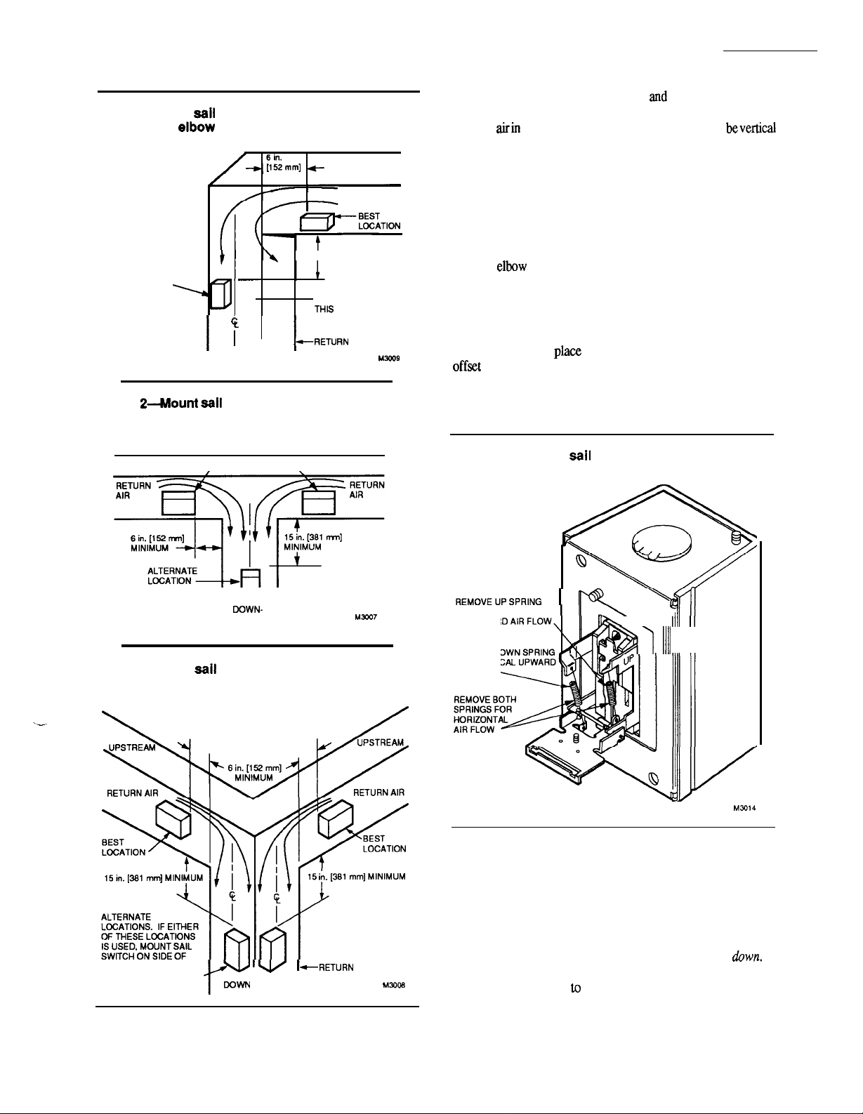
Fig. l-Mount
shown for
is recommended.
ALTERNATE
LOCATION. MOUNT SAIL
SWITCH ON THIS SIDE
OF DUCT, OPPOSITE
AIR ENTRANCE.
Fig. 2-hIlount eaii switch on center iine of duct
in one of angle-t positions shown for junction
duct work.
UPSTREAM
switch in one of positions
UPSTREAM
MINIMUM
RETURN AIR
15
in.
[381 mm] MINIMUM
DO NOT MOUNT ON
SIDE OF DUCT.
AIR DUCT
DOWNSTREAM
I
/ BEST LOCATION \
I
UPSTREAM
must beat
least 12 in. [305 mm] deep
8 in. [203 mm] wide
to allow operation of the sail without affecting the smooth
flow of
(up or down) or horizontal.
NOTE: When S688 is mounted in warm air, the sail life may
be reduced.
Refer to Figs. 1-3 for the best duct mounting location.
Mount the switch at least 6 in. [152 mm] upstream from an
elbow or junction, and at least 15 in. [381 mm] downstream
from an
or junction. The switch must be located on the
opposite side of the duct from the air entrance.
ADAPT SWITCH TO AIR FLOW DIRECTION
The S688A Saii Switch is provided with two counterbalancing springs in
IMPORTANT:
Never
as shown in Fig. 4. These springs
use the sail switch with both springs
attached.
Fig. 4-Adapting
tion.
switch to air flow direc-
RETURN AIR DUCT
Fig. 3-Mount
shown for angle-t junction duct work. Transition in trunk is recommended.
OUCT OPPOSITE AIR
ENTRANCES AS SHOWN.
--1-1
STREAM
switch in one of positions
RETURN
DOWNSTREAM
AIR DUCT
I
FOR VERTICAL
00WNWARO AIR FLOW
REMOVE DOWN SPRING
FOR VERTICAL UPWARO
AIR FLOW
\
6
II
II
Adapt the sail switch to mounting position. (F52 requires
special instructions; see separate instructions.)
Standard Application
Horizontal air flow-remove both springs.
Vertical
upward air
flow-leave in place the spring that
is attached to the bracket marked up.
Remove the
spring that is attached to the bracket marked
Vertical
downward air
that is attached
the
spring that is attached to the bracket marked
flow-leave in place the spring
the bracket marked
down. Remove
up.
3
60-2103-3
Page 4
S688A
INSTALLATION
F52 Application
Ceiling-remove both springs.
All
positions-leave in place the spring that is
attached to the bracket marked
Remove the
that is attached to the bracket marked
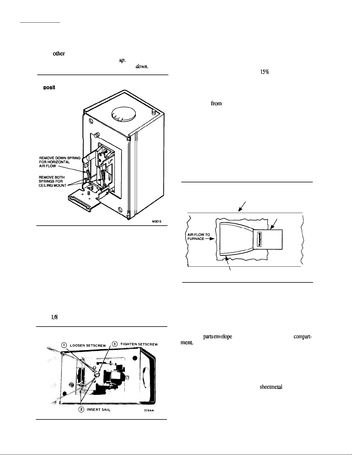
Fig. 5-Adapting sail switch to F52 mounting
ion.
spring
4. Attach the
sail to the switch as shown in Fig. 6.
NOTE: The sail switch makes at about 250 fpm and breaks
at 75 fpm. In an average residential system that produces
500 fpm in the return air duct, the switch will make at
approximately 50% and break at
of the maximum air
flow rate. In a system where air flow maybe as high as
1000 fpm the switch will not break until the airflow drops
to about 7.5% of maximum. To retain the original on-off
ratios of air flow, mm the sail. Trim about 1-1/2 in.
[38 mm]
the sail for 1000 fpm air velocity and
proportionally more or less for higher or lower velocity.
Correct trimming is important. If sail is too long, it will
flutter and the wire frame may break prematurely; if it is
too short, the switch may not operate.
5. Press the sides of the wire loop together. Insert the sail
into the duct.
6. Before fastening the switch in position, check to make
certain air movement will operate the switch. In the off
position, the sail should point into the direction of airflow as
shown in Fig. 7.
Fig. 7-Position sail so it points into the
direction of airflow when switch is off.
DUCT
MOUNT THE SWITCH (See special
instructions forF52)
The sail switch counterbalancing springs are calibrated
for proper operation when the sail switch case is mounted at
true level for horizontal air flow applications, or plumb for
vertical air flow applications. Proceed as follows, using the
mounting template provided.
1. Mount the template at desired location. BE SURE
THAT THE ARROW INDICATING AIR FLOW POINTS
IN THE PROPER DIRECTION. Level the long dimension
shown on the template for horizontal mounting. Plumb this
dimension for vertical mounting.
2. Cut the hole indicated on the template in the ductwork.
3. Center punch the screw holes indicated and drill out
with a
inch drill.
Fig. 6-Attaching sail to switch.
provided. After wiring, snap on the cover. The Honeywell
trademark tab can be snapped out and rotated 180 degrees so
it will be upright for any vertical mounting position.
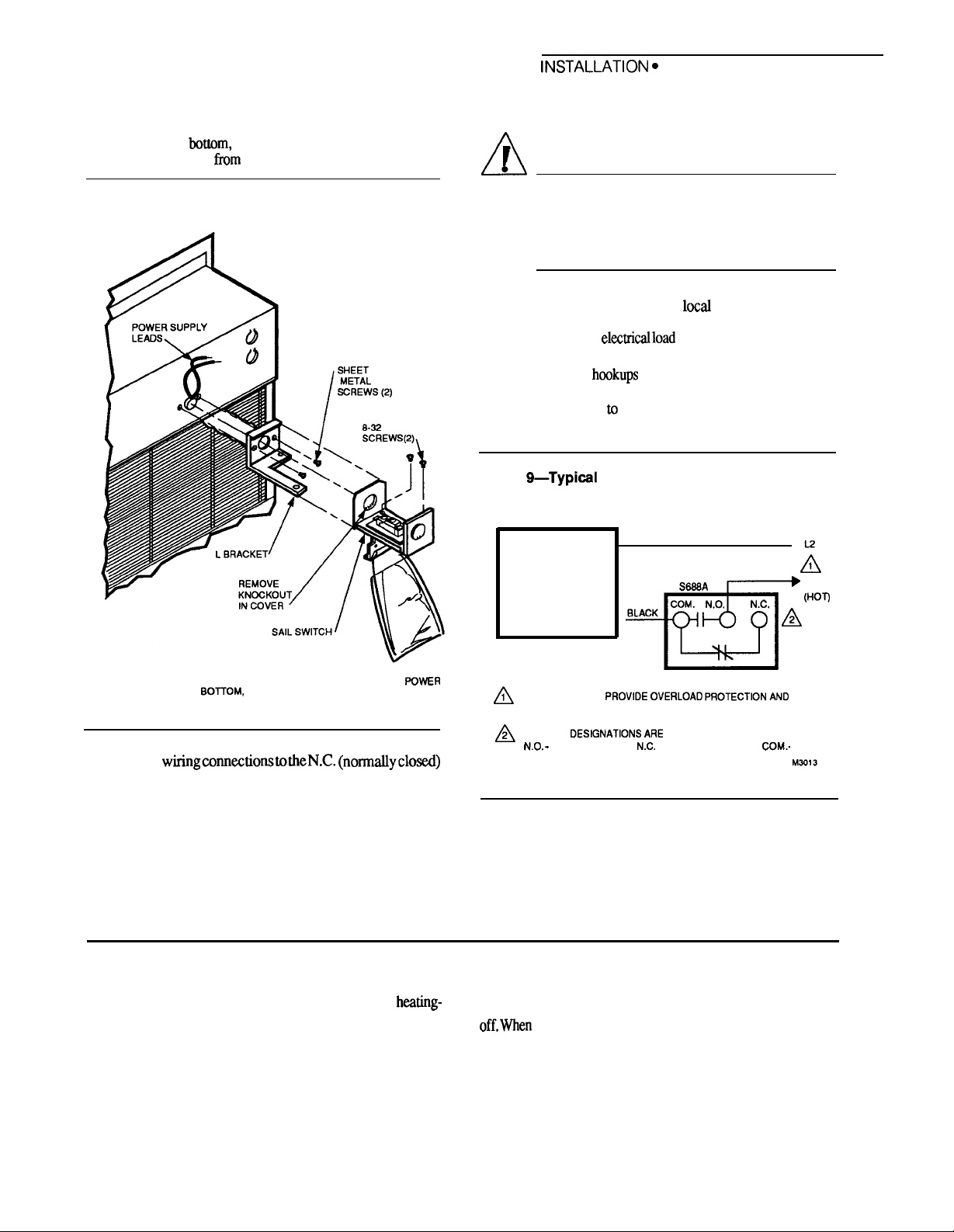
MOUNT SAIL SWITCH ON THE F52
and small
site of the arrow stamped on the inside of the case.
the power supply. Pull wires
case knockout. Using two tapered
the envelope, mount the L-shaped bracket to the air cleaner.
Next, remove the ground screw on the sail switch to prevent
interference with the L-shaped bracket. Mount the sail switch
to the L-shaped bracket with two 8-32 screws. Airflow
should be in opposite direction of airflow arrow.
SAIL SWITCH
\
SAIL IN OFF POSITION:
POINTS INTO AIR FLOW
/
M301 O
7. Secure the switch by using the sheet metal screws
1. Remove the sail switch, L-shaped mounting bracket
from the air cleaner wiring
2. Remove sail switch coverandremoveknockout oppo-
3. Turn the air cleaner over and rest it on the carton.
4. Mount the sail on the sail switch.
5. Locate the two black wires extending from the back of
through
L-shaped bracket and
screws from
4
Page 5
S688A
OPERATiON AND CHECKOUT
NOTE: Although it is not recommended, if the two-cell air
WIRING
cleaner must be mounted horizontally with the power
supply on the Wtom, the sail switch must be installed at
a 45 degree angle
Fig. 8-Mount sail switch on back of power
supply.
vertical, see Fig. 8.
ordinances. When controlling more than one device, make
certain that the total
rating (see Specifications).
the sail switch are shown in Fig.
normally closed refer
de-energized position.
CAUTION
●
ELECTRIC SHOCK HAZARD.
CAN CAUSE ELECTRICAL SHOCK OR
EQUIPMENT DAMAGE.
Disconnect power supply before wiring.
All wiring must comply with
electrical codes and
does not exceed the switch
Typical wiring
that have the switching action at
9.
Normally open and
the contacts when the switch is in the
Fig. 9—Typicsl wiring hookups using sail
switch to energize electronic air cleaner.
WHITE
➤
NOTE: IF AIR CLEANER IS MOUNTED HORIZONTALLY WITH THE POWER
SUPPLY ON
A 45 DEGREE ANGLE FROM VERTICAL.
6.
Make
M3011
and COM (common) screw terminals in the sail switch.
7. Replace sail switch cover.
Operation and Checkout
OPERATION
The
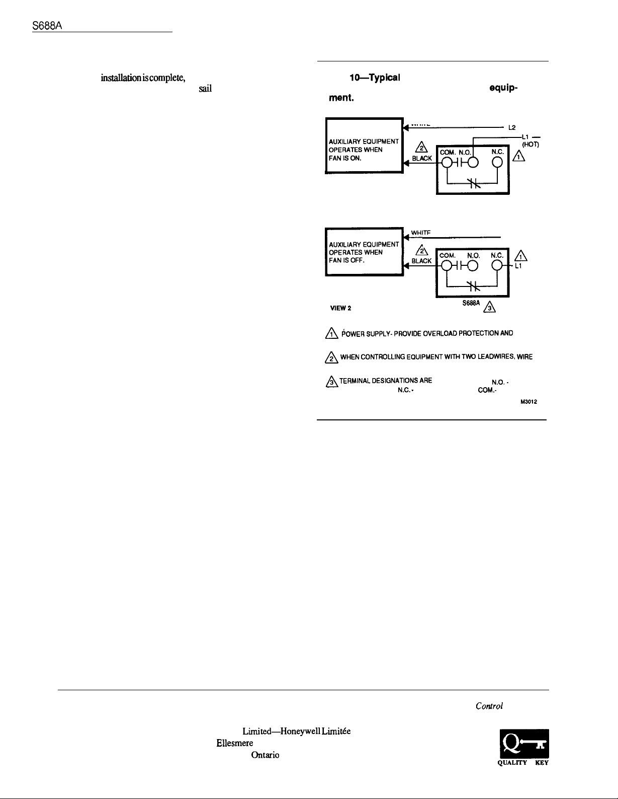
sail switch has a spdt switch, which permits different
hookups for controlling auxiliary equipment in a
cooling system. The hookups in Figs. 9 and 10, show systems
where the controlled equipment operates only when the
system fan operates. When the fan produces 250 fpm air
velocity, the normally open contacts make, turning on the
auxiliary equipment. When the air velocity decreases to 75
fpm, the
auxiliary equipment. The hookup in Fig. 10 shows a system
where auxiliary equipment operates when the system fan is
closed contacts break, turning off the auxiliary equipment.
When the air velocity decreases to 75 fpm, the normally
closed contacts make, turning on the auxiliary equipment.
EAC
COM.
BLACK
POWER SUPPLY- F’ROVIDEOVERLOAD F’ROTECTIONAND
DISCONNECT MEANS AS REQUIRED.
TERMINAL DESIGNATIONSARE FOR POWER OFF:
NORMALLY OPEN,
COMMON.
normally
open contacts
- NORMALLY CLOSED, COM.-
break, turning off the
L1
the fan produces 250fpm air velocity, the normally
5
60-2103-3
Page 6
OPERATION AND CHECKOUT
CHECKOUT
When
one complete cycle to make sure
described in OPERATION section.
operateequipmentthrough
switch functions as
Fig.
wiring hookups using sail
switch to energize two-wire auxiliary equip-
WHITE
VIEW 1
-AA
POWEFIS.PPLY-PROVlDEOVERL0ADPROTECTi0NAf4D
DISCONNECT MEANS AS REQUIRED.
WHEN CONTROLLING
SWITCH 1“ HOT (BLACK) LINE.
TERMINALDESIGNATIONSARE FOR POWER OFF: N.O.-
NORMALLY OPEN,
NORMALLY CLOSED, COM.- COMMON.
—
—
(HOT)
WIRE
Residential and
Residential and
Building Controls Division Building Controls Division
Honeywell Inc.
1985 Douglas Drive North
Golden Valley, Minnesota 55422
Honeywell
740
Scarborough,
MIP 2V9
Limitie
Honeywell
Helping You
Your World
 Loading...