

Honeywell S4965 Product Handbook
PRODUCT HANDBOOK
1 EN2R-9053 0408R11-NE
Subject to change without notice. All rights reserved.
S4965 SERIES
COMBINED VALVE AND BOILER CONTROL SYSTEMS
APPLICATION
The S4965 boiler controls have been developed for application
in gas fired domestic appliances.
The S4965 boiler controls are used in conjuction with the
VK41.. series modulating or non modulating gas controls. (see
Product Handbook EN2R-9025 and EN2R-9004) They provide
both an optimised safety sub-system for programmed safe
light-up and flame supervision of the main burner of the
appliance and a boiler comfort control sub system for
temperature, pump, and 3-way valve control
Bi-directional communication with a MMI enables
comprehensive diagnostics and operation.
For glossary of terms, abbrevations and symbols see
document EN2R-9039
Contents
General
Description ......................................................................... 2
Features ............................................................................ 3
Dimensional drawing S4965 boiler control ........................ 4
Technical
Specifications .................................................................... 5
Connection diagram ..........................................................7
Timing diagram ................................................................8
Description of LOCON ......................................................9
Description of SQUARE...................................................10
General considerations ................................................... 11
Electrical connections and wiring ....................................12
Adjustments and final checkout ......................................13
Various
EMC guidelines ............................................................... 14
Quality assurance statement ........................................... 15
Standards and approvals ................................................ 15
Ordering information .......................................................16

EN2R-9053 0408R11-NE 2
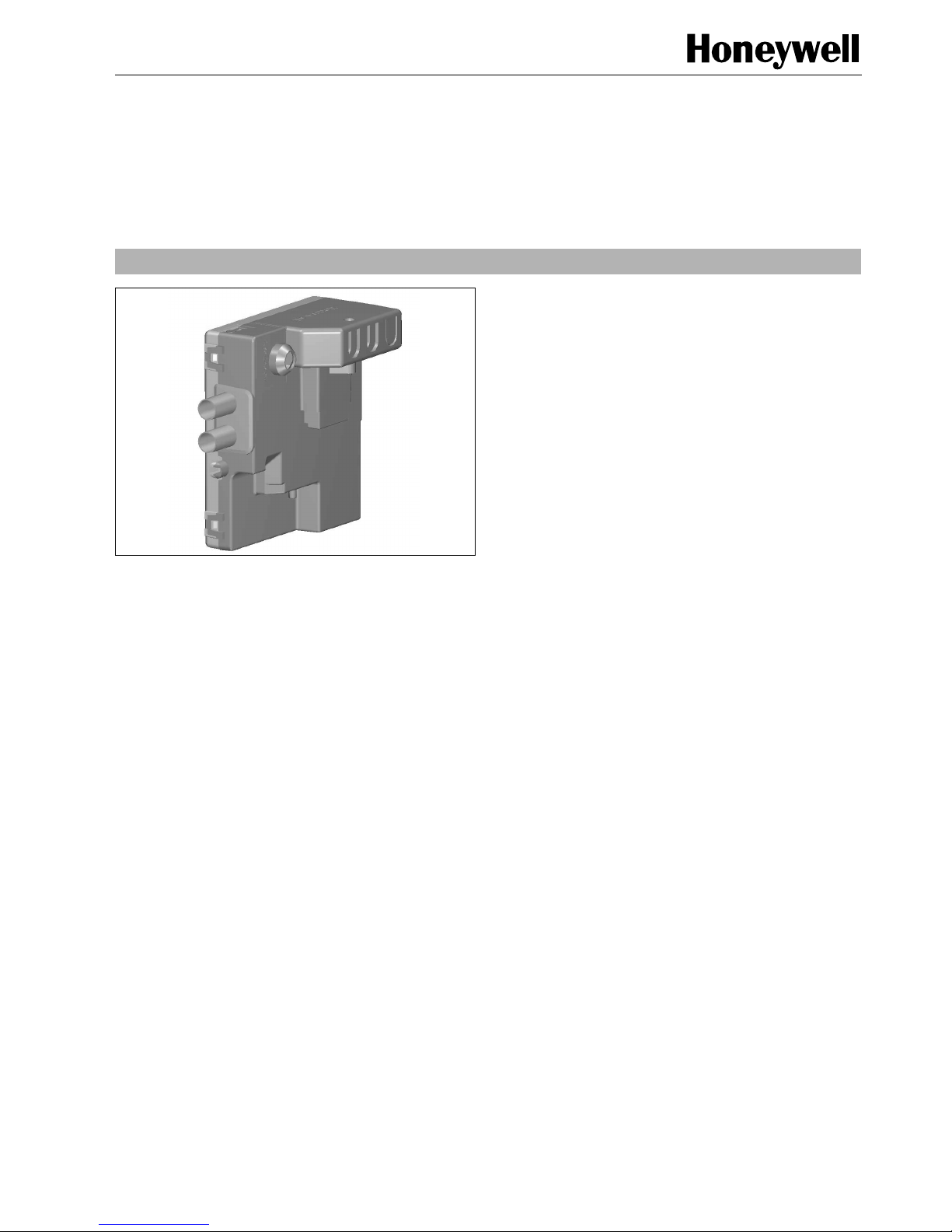
DESCRIPTION
The Combined Valve Boiler Control (CVBC) is the
combination of a VK41.. modulating or non-modulating gas
control with an electronic boiler control.
The boiler control consists of an automatic ignition control and
a comfort boiler control.
Most of the standard control functions of a gas fired boiler can
be performed within one single control box which can easily be
clicked on the gas control.
Possible applications are:
• Instantaneous water heaters.
• Floor standing boilers.
• Combi boilers.
• Low Nox boilers.
• Condensing boilers.
• See chapter Features for the standard features which can
be implemented in this control box.
ALARM
RESET

3 EN2R-9053 0408R11-NE
FEATURES
• Multi trial full sequence ignition control.
• Permanent operation in accordance with EN 298 (2003).
• Non volatile lock-out.
• Self learning ignition sequence; no minimum adjustment,
using LOCON.
• Direct Burner- or Intermittent Pilot operation.
• Integral ignition including emission filter.
• Combined ignition and flame sensing option.
• Phase insensitive flame detection.
• Lock-out at flame simulation.
• Restart after flame loss.
• AC or DC fan control (24 VDC fan needs external trafo).
• Dynamic airflow check.
• Lock-out on no air.
• Automatic fan assisted/atmospheric recognition.
• Integral gas pressure modulation circuitry.
• Pump control.
• 3-way valve control.
• Multi temperature CH and DHW control with DHW priority
setting.
•∆T control in CH mode
• Flow sensor input for DHW detection and control
• Sensor- or contact switch high limit at control.
• Communication to MMI enabling comprehensive
diagnostics and operation.
• Factory safety parameter settings.
• Installer and OEM comfort boiler control parameter
settings.
• On board transformer and wiring center.
• Integral and/or remote reset and alarm indicator.
• Electrical safety in accordance with EN 60730-1 (2000).
• Replacable fuse
• OpenTherm communication
EN2R-9053 0408R11-NE 4
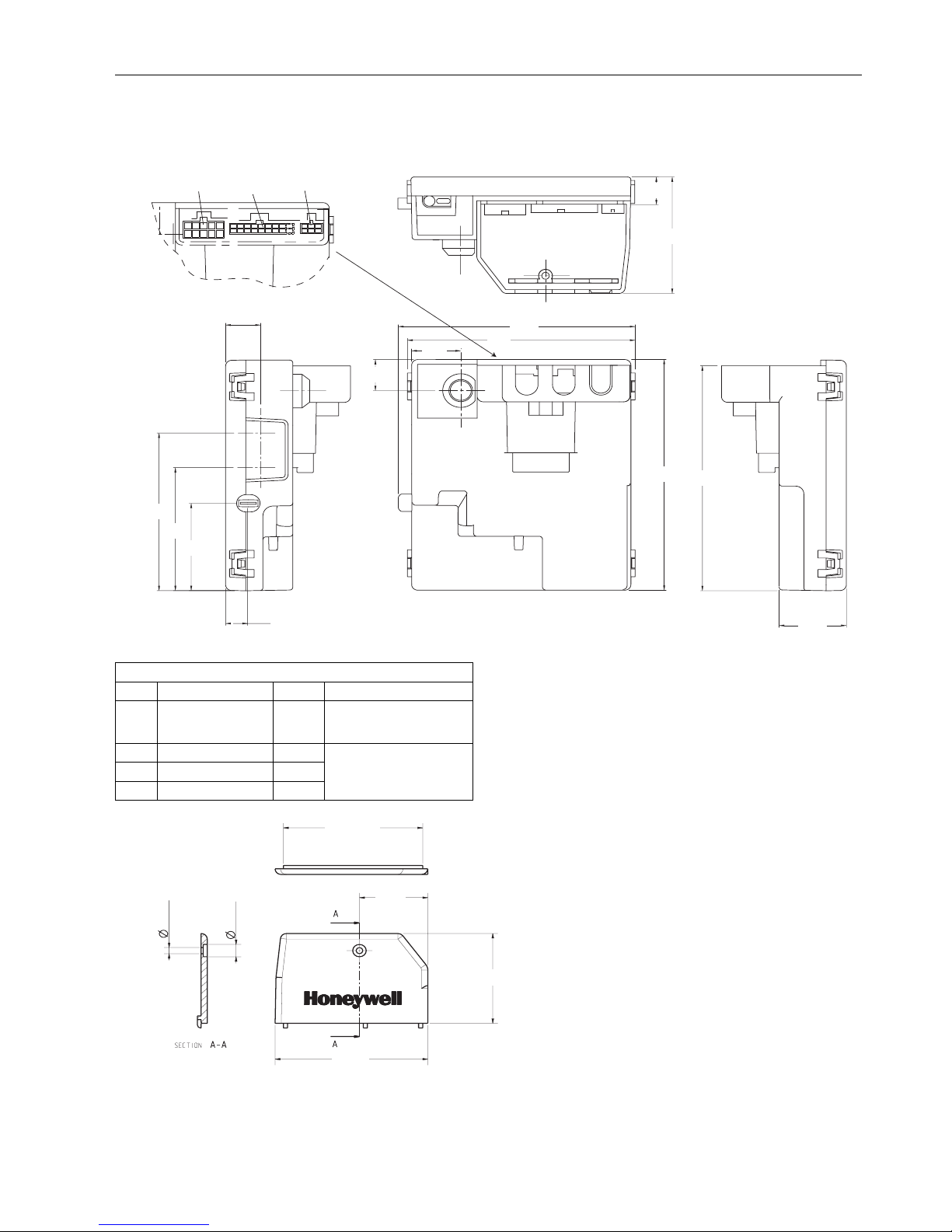
DIMENSIONAL DRAWING S4965 BOILER CONTROL
Molex Minifit (for X1) and Microfit (for X11 and X12) can be
used as alternatives
Dimension cover
110
115
120
117
82
64
46
17
12
61
14
33
24
16
1
6
3
1
1
8
9
16
18
15
10
X11X12X1
Material : ABS - V0
Tolerances ± 1 mm
unless noted
FOR CONNECTORS, USE FEMALE PARTS
Plastic part Pins Terminal
X1 TYCO 1-106527-0 10 TYCO 106528-2 (reel)
(for AWG 22-26, insulation
diameter 1,20 - 1,75 mm)
X11 TYCO 794617-6 6
TYCO 794607 (reel)
TYCO 794611
(for AWG 26-30)
X12 TYCO 1-794617-6 16
X12 TYCO 1-794617-8 18
6,6 ± 0,4
3,3 ± 0,3
68,1 ±0,3
33,4
74,65
48,2
Material : ABS - V0
Tolerances ± 1 mm
unless noted
5 EN2R-9053 0408R11-NE
SPECIFICATIONS
Models
Basically there is one PCB for a number of applications.
Depending on which components are mounted different
applications can be covered.
Supply voltage
230 Vac -15% +10%
50Hz ± 2%
Power consumption
5 VA
Humidity
90% RH max. at 40°C (non condensing)
Ambient temperature
-20 ... 60°C
Electrical rating
fusing: external: 2 A slow, sand filled
optional integral: 2A slow, sand filled
230V output 1 (ac fan or lpg valve):
230 Vac, 0.8 A max, cos ϕ ≤ 0.6
230V output 2 (pump or aux):
230 Vac, 0.8 A max, cos ϕ ≤ 0.6
230V output 3 (3 way or aux):
230 Vac, 0.8 A max, cos ϕ ≤ 0.6
230V output 4 (3 way or aux):
230 Vac, 0.8 A max, cos ϕ ≤ 0.6
Total output (1..4) : 2A
Room thermostat input:
230 Vac, 1 mA or by communication
Gas valve output: :
230Vrac, 50mA
Auxilary input:
12 Vdc, 100 kOhm
Air pressure switch input:
12 Vdc, 100 kOhm
DC fan control output:
5 V 10 mA
High limit switch input:
5 Vdc, 100 kOhm
Water pressure switch input:
12 Vdc, 100 kOhm
Flow sensor input and output:
12 ± 4Vdc, 10 mA max supply open collector input
Alarm output:
12 Vdc, 5 mA or by communication
OpenTherm output and communication:
In accordance with OpenTherm standard
Sensors inputs (total maximum 6):
Standard NTC T7335 10k-A material
(see survey S-T7335)
High limit dual sensor 10 kOhm NTC *
(Sensor type : T7336B 1001)
* this sensor needs special input
MicroCom Communication input and output:
input: logic “0” < 0.8 Vdc
logic “1” > 2 , < 24 Vdc (10 kOhm)
output: open collector 24 V and 10 mA max
DC output: depending on OS number:
9Vrac, 5mA max
or 24Vdc, 50mA and 7V, 250mA
Electrical PCB connectors
High voltage spark: 2.8 x 0.5 mm faston
or 4 mm round.
Flame sensing: 4.8 x 0.8 mm faston
Mains connector: 10 pole TYCO, AMP-duac
Low voltage connectors: 16 or 18 and 6 pole TYCO,
MATE-N-LOCK
Flame sensing
Factory parameter setting:
minimum flame current settable between 0.5 and 5 µA
Response time ON: < 0.2 s
Response time OFF: < 1 s
Ignition
Spark voltage: 15 or 20 kV @ 30pF
Spark frequency: 15 Hz
Spark pulse energy: 4 or 15 µAs
Timing
Pre purge time: 0 ... 51 s
Waiting time (T
w
): 0 ... 51 s
Pre ignition time: 0 ... 51 s
Safety time (T
s
): 0 ... 51 s
Number of retrials: 0 ... 255
Flame failure response time: 1 s
Stabilisation time: 0 ... 51 s
Post ignition/stabilisation time: 0 ... 51 s
Post purge time: 0 ... 51 s
Pump over run time: 0 ... 600 s
Anti cycling time: 0 ... 255 s
Timing tolerance ± 5%
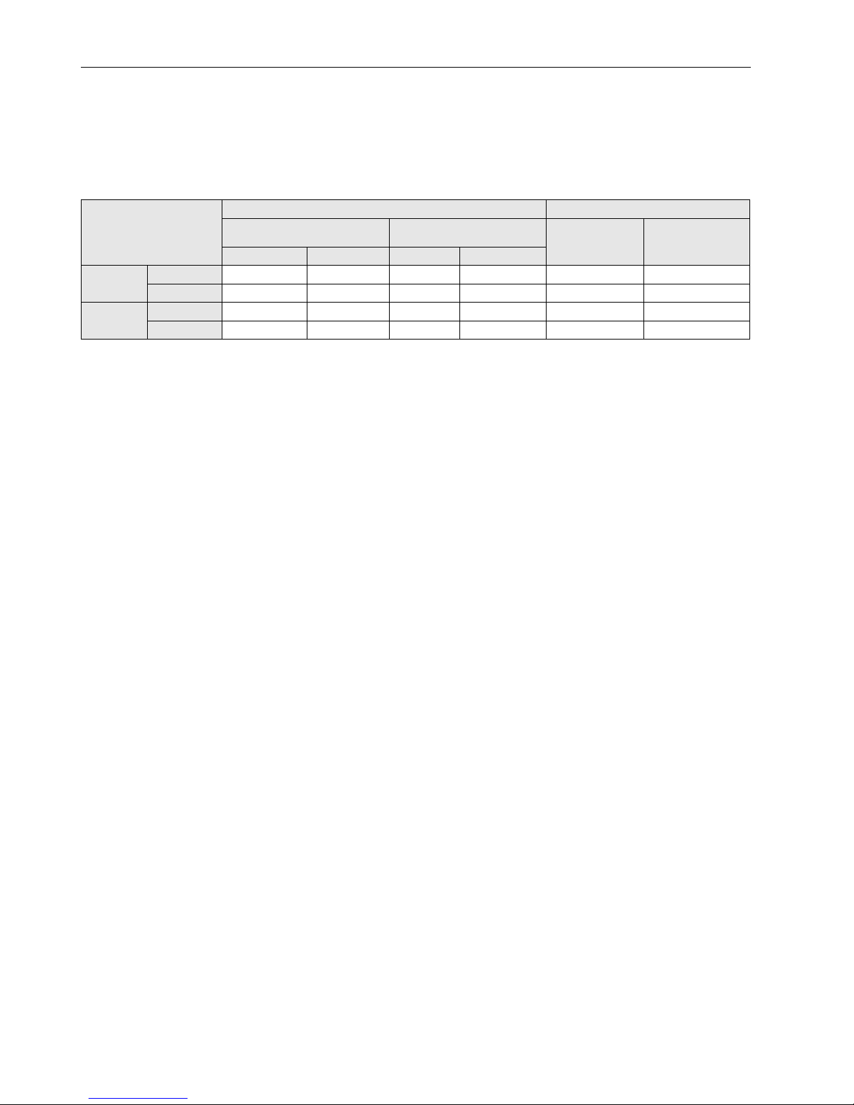
Application
Atmospheric combustion Premix combustion
Normal Combustion feedback
(LoCon)
Normal
(Pneumatic
gas/air)
SQUARE
(Electronic gas/air
or Gas addaptive)
Open flue Fan assistant Open flue Fan assistant
On /Off
Electronics S4965A S4965C ------------- ------------- S4965V -------------
Gasvalve VK4105A2/C2 VK4105A2/C2 ------------- ------------- VK4115V2 -------------
Modulation
Electronics S4965AM S4965CM S4965AL S4965CL S4965V S4965S
Gasvalve VK4105G1 VK4105G1 VK4105G2 VK4105G2 VK4115V2 VK4105G3
 Loading...