

Honeywell S4565, S4575, S4585 Production Handbook
PRODUCTION HANDBOOK
1 EN2R-9031 0402R15-NE
Subject to change without notice. All rights reserved
S4565, S4575 AND S4585
IGNITION CONTROLS FOR COMBINED VALVE AND IGNITION SYSTEM
APPLICATION
The Combined Valve and Ignition (CVI) system has been
developed for application in gas fired domestic central
heating boilers, combi boilers and warm air furnaces or water
heater appliances with an automatic ignition system.
For this system, the S4565, S4575 and S4585 ignition
controls are used in conjunction with the VK41.. series gas
controls to provide and optimised safety sub-system for
programmed safe light up and flame supervision of the main
burner of the appliance
The combined system then provides programmed safe light
up, flame supervision and regulation of gas flow to the main
burner and/or pilot burner of the appliance.
NOTE: The Combined Valve and Ignition (CVI) product concept consists of a specially designed gas valve family in
combination with a dedicated ignition controls family. This product handbook describes the CVI ignition controls family
S4565, S4575 and S4585 for use in combination with the CVI gas control family VK41.. For details of the CVI gas
controls please refer to Product Handbook EN2R-9004. For an up-to-date copy please contact your nearest
Honeywell office. For glossary of terms, abbrevations and symbols see document EN2R-9039

EN2R-9031 0402R15-NE 2
CONTENTS
General Page
Description 3
Features 4
Dimensional drawing housing 5
Dimensional drawing “old style” housing 6
Accessories for degree of protection IP 20, IP 40, IP X4, IP 44 7
Assembling of IP X4/44 housing 8
Application S4565/S4575/S4585 ignition controls 9
S4565 ignition controls
Specifications S4565A, B ,P, Q 10
System operation S4565A, B, P, Q 12
Specifications S4565C, D, R, T 14
System operation S4565C, D, R, T 16
Specifications S4565AD, BD, CD, DD, PD, QD, RD, TD “1000” series 18
System operation S4565AD, BD, CD, DD, PD, QD, RD, TD “1000” series 22
Specifications S4565AD, BD, CD, DD, PD, QD, RD, SD, TD “2000” series 25
System operation S4565AD, BD, CD, DD, PD, QD, RD, SD, TD “2000” series 30
Specifications S4565AF, BF, CF, DF, PF, QF, RF, TF 33
System operation S4565AF, BF, CF, DF, EF, PF, QF, RF, TF 35
Application note S4565BF with second main valve control 38
Application note S4565DF, TF with external main burner interrupt 39
Specifications S4565PV, QV, RV, TV 42
System operation S4565PV, QV, RV, TV 45
S4575 ignition controls
Specifications S4575A, B, P, Q 50
System operation S4575A, B, P, Q 52
S4585 ignition controls
Specifications S4585D 54
System operation S4585D 57
Var ious
General considerations 59
Installation
EMC guidelines 60
Electrical connections and wiring 61
Quality assurance statement 62
Standards and approvals 63
Ordering information 64
Overview ignition controls 65
Replacement parts and accessories 66
Cable assemblies 66

3 EN2R-9031 0402R15-NE
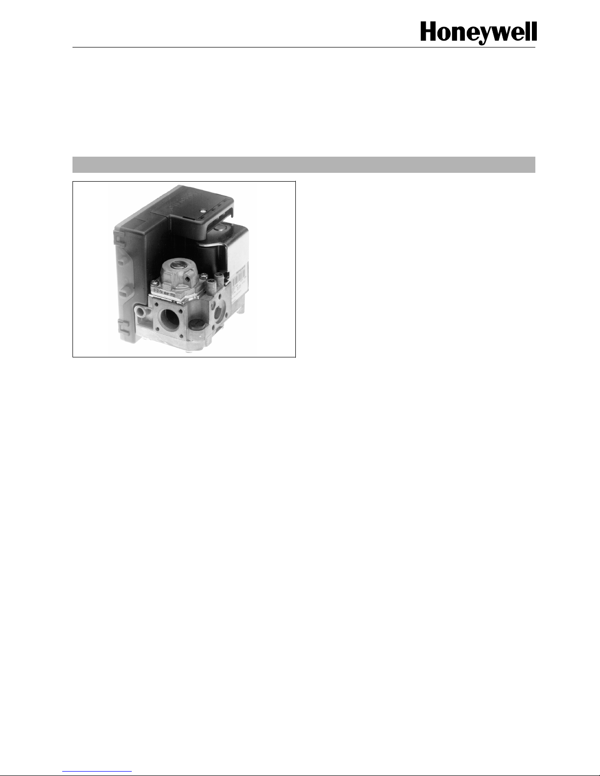
DESCRIPTION
Val ves
The Combined Valve and Ignition (CVI) system controls and
performs all the functions required for safe ignition, flame
supervision and for safely regulating the gas flow to the pilot
and/or main burner.
The CVI consists of a gas valve of the VK41.. series and a
dedicated ignition control of the series S4565, S4575 and
S4585 which is connected directly on to it.
Ignition control
The S4565, S4575 or S4585 220/240 Vac series ignition
controls can be directly electrically connected to a VK41..
series gas control. (S4575 can also be rated 110 ... 120Vac)
The S4565/S4575 ignition controls are not intended for direct
exposure to flame envelope.
S4565, S4575 and S4585 ignition controls give excellent
performance and a high reliability standard. There are
versions available for different ignition systems:
The S4565/S4575 ignition controls are approved on the
North American standard ANSI Z21.20 Automatic Ignition
Systems.
S4565, S4575 and S4585 systems function in accordance
with EN 298.
• S4565
Direct Burner Ignition (DBI) or Intermittent Pilot ignition
(IP) with a defined safety time for applications with or
without fan, with flame detection, volatile or non volatile
lock out, optional remote reset, fixed waiting times and in
case of flame failure recycling of the full start up
sequence.
• S4575
Hot Surface Ignition (HSI) with a defined safety time for
applications with or without fan, with flame detection,
volatile or non volatile lock out, optional remote reset,
fixed waiting times and in case of flame failure recycling of
the full start up sequence.
• S4585
Intermittent Pilot ignition (IP) for atmospheric or fan
assisted applications with the so called ”wild pilot system”
without safety time for ignition, with flame detection on the
pilot flame. Wild pilot system means a safety T
s
+ ∞ and is
applicable for pilot burners up to 250 Watt
Intermittent Pilot ignition (IP) for atmospheric or fan assisted
applications with the so called ”wild pilot system” * without
safety time for ignition and flame detection on the pilot flame.
The performance and the construction of the ignition control
is optimized and dedicated to the VK41.. series gas controls.
NOTE: S4565SD is not an ignition control but an ignition
circuit and rectifier only

EN2R-9031 0402R15-NE 4
FEATURES
General
• All burner control safety functions concentrated in one
reliable and optimized system.
• Specially designed to provide the optimum system
solution in gas appliances with a DBI or IP system to light
the main burner.
• Both gas control and ignition control incorporate time
proven design concepts assuring reliability.
• Easy assembly of ignition control on gas control by
plugging it on from the top.
• Mounting orientation may be within 90° in any direction
from the electric on/off operator upright position.
Ignition control
• Hybrid technology for high reliability.
• Flame supervision.
• Built-in 2.5 ... 60 Hz ignition.
• Internal or external reset and alarm.
• Accurate safety timer.
• Supply voltages of 220/230 ... 240 V 50/60 Hz in a single
product. (S4575 can also be rated 110 ... 120Vac)
• Full operating sequence after flame loss.
• Extended spark ignition.
• Optional phase neutral independent operation, flame
sensing independent of safety ground potential for
S4565AD ... TD “2000” series and S4575.
• Safety time triggered by Air Pressure Switch (APS) for
S4565AD ... TD “2000” series.
• Optional safe separation flame relay output or opto
coupler.
• Optional main burner interrupt for S4565BF, DF, QF, TF.
• Volatile or non volatile lock-out according to EN 298.
• EMC filter optional.
• Protective impedance flame rod.
• Under voltage protection.
• Flame relay option.
• Option of separate power supply and heat demand input.
• Optional flame retarding housing (UL 94-V0)
Electrical connection options
• Connection to the gas control is made entirely by
plugging the ignition control on.
• Electric connections are positioned on top and are made
by a multiple plug-in connector (IP 20 enclosure if side
connections are accessible).
• The housing can receive a cover for strain relief in order
to have an IP 30 or an IP 40 enclosure,(if side
connections are accessible). When the cover is applied in
combination with the cable seal grommet, sleeves and
gasket the enclosure is IP X4 (IP 44 if side connections
are accessible)
• Ignition and flame detection connections are at the outlet
end of the housing.
• Flame detection is accessible.
• Volt free relay of S4575 is accessible.
• Ignition connection is accessible if f
s
t 25 Hz and ignition
and flame sensing is separate.
• Ignition connection AMP 2.8 x 0.5 mm.
• Flame detection connection AMP 4.8 x 0.8 mm in case of
separate ignition and flame sensing.
5 EN2R-9031 0402R15-NE
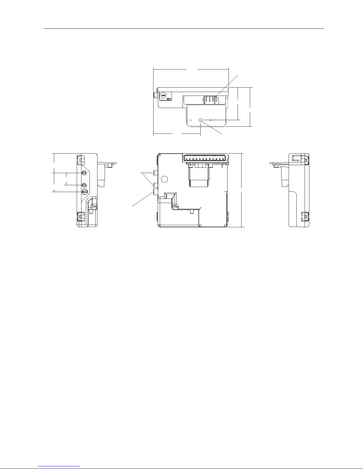
DIMENSIONAL DRAWING HOUSING
Fig. 1. Dimensional drawing housing in mm
Ignition
72
115
60
50
113
Mounting hole Ø 3.2
Flame detection
30
29
19
Connector pins suitable for
Molex 3001 female connectors
Note: specific housings may deviate from drawing
EN2R-9031 0402R15-NE 6
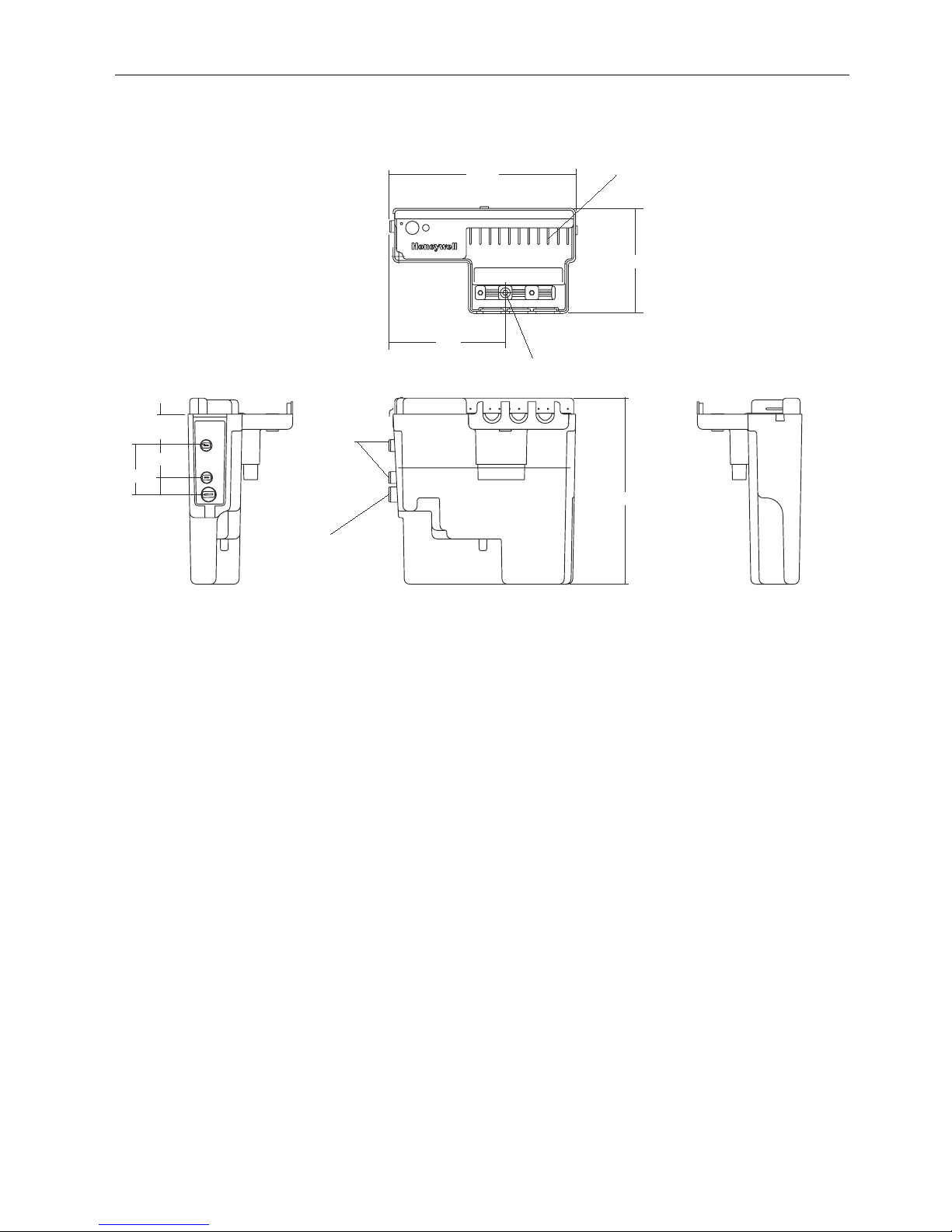
DIMENSIONAL DRAWING “OLD STYLE” HOUSING
Fig. 2. Dimensional drawing “old style” housing in mm (do not use for new designs)
111
Connector pins suitable for
Molex 3001 female connectors
62
Mounting hole Ø 3.2
69
29
19
18.5
69
110
Ignition
Flame detection
Note: specific housings may deviate from drawing
7 EN2R-9031 0402R15-NE
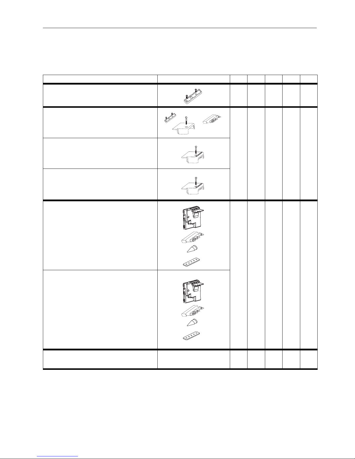
ACCESSORIES FOR DEGREE OF PROTECTION IP 20, IP 40, IP X4, IP 44
See also Replacement parts and Accessories on page 66.
1
) For IP 20 the cable grommet may be left out.
2
) Classification valid after correct installation of wires.
3
) Only if the spark frequency is larger than 25 Hz or in case
of combined ignition and flame sensing or if the side connections have DC or AC output then additional protection
against electrical shock shall be provided for these connections by the application manufacturer since in such
case the side connections must be considered as hazardous live parts.
IP 00 IP 20 IP 40 IP X4 IP 44
Optional strain relief
Order number: 45900442-007 or- 011: 45900440-001 (
screws included)
Cover set with separate strain relief
Order number: 45900440-001 (screws included)
Order number: 45900431-005
Order number: 45900431-007 (screw included)
Choose one cover set 1)
Choose one cover set 1)
Choose one cover set 1)
Choose one cover set 1)
Cover set with integrated strain relief
Order number: 45900431-004 (screw included)
Cover set with integrated strain relief, flame
retarding in accordance with UL 94 V0.
Order number: 45900431-005 (screw included)
Special housing for IP X4/44
See O.S. card
Color: grey and red
Cable grommet
Order number: 45900442-008
Sleeve
Order number: 45900442-003 or- 006
Gasket
Order number: 45900442-007 or- 011
Choose one set (housing with accessoiries) 2)
Choose one set (housing with accessoiries) 2)
Special housing for IP X4/44, flame retarding in
accordance with UL 94 V0
See O.S. card
Color: black
Cable grommet
Order number: 45900442-008
Sleeve
Order number: 45900442-003 or- 006
Gasket
Order number: 45900442-007 or- 011
Additional means for electrical protection of side
outlets
To be provided by the appliance
manufacturer
Use 3)
Use 3)
Use 3)
EN2R-9031 0402R15-NE 8
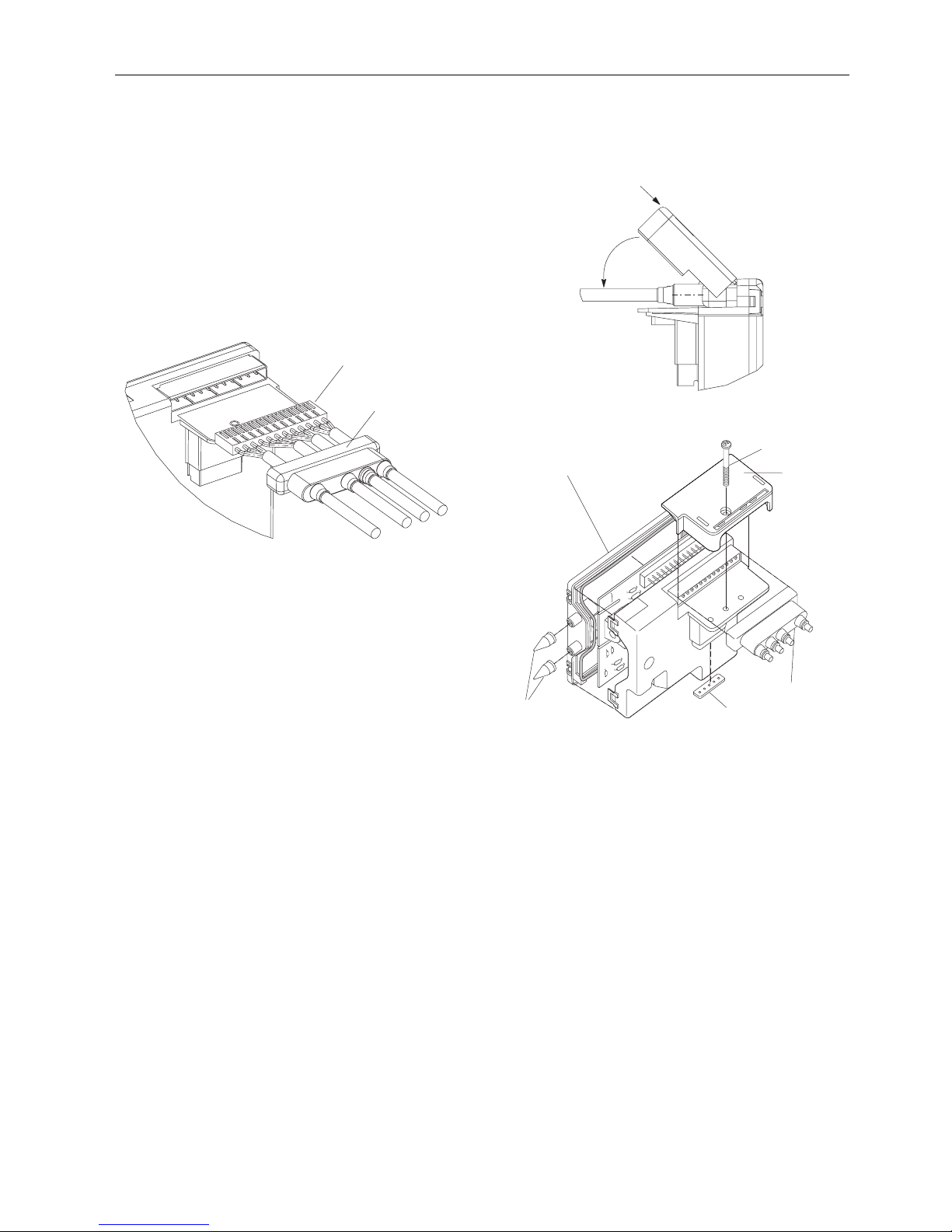
ASSEMBLING OF IP X4/44 HOUSING
Assembling of the cable connector(s) and cover (see Fig. 3. and Fig.
5.)
• Use cable with Ø 5 ... Ø 7 mm.
• Strip length cable: 15 mm
• Grommet inlet nunmbers1, 2, 4 applicable for cable
with Ø 5 ... Ø 7 mm.
• Grommet inlet number 3 applicable for cable
with Ø 4 ... Ø 7 mm.
• Mount the connector(s) and bring the cable grommet in
position over the cables and connector.
Fig. 3.
Assembly of strain relief for IP X4/44 protection (see Fig. 4. and Fig.
5.)
Position the cover on the ignition control Then, when holding
the cover down (in direction A) rotate it to mount the cable(s)
in the strain relief (in direction B).
Place the gasket on the pins of the gas control and finally fix
the whole assembly (ignition control and cover) with a screw
on the gas control wit a torque of 40 Ncm max.
Use sleeves to connect the flame sensing wire and sparking
connection(s).
In case the spark plug connections are not accessible,
additional means for electrical protection need to be provided
by the boiler manufacturer if IP 44 is needed. The spark plug
connections must not be removable without the use of a tool.
Fig. 4.
Fig. 5.
Cable grommet
Connector
1
3
2
4
A
B
Special housing for IP X4/44
Fixing screw
Cap
Cable grommet
Gasket
Sleeves

9 EN2R-9031 0402R15-NE
APPLICATION
The S4565, S4575 and S4585 series ignition controls have
been specially developed for application in gas fired domestic
appliances.
The S4565, S4575 and S4585 series ignition controls are
used in conjuction with the VK41.. series gas controls to
provide and optimised safety sub-system for programmed
safe light-up and flame supervision of the main burner of the
appliance.
In S4565 series there are versions available for both Direct
Burner Ignition (DBI) and Intermittent Pilot (IP) ignition
systems with a defined safety ignition time.
The S4575 series are suitable for Hot Surface Ignitors.
The S4585 series can be used for appliances with ”Wild
Pilot” Intermittent Pilot systems. (Wild pilot means a safety
time T
s
= ∞ and is applicable for pilot burners up to 250 Watt.)

EN2R-9031 0402R15-NE 10
SPECIFICATIONS S4565A, B ,P, Q
Model
Suffix A: atmospheric, direct burner ignition
Suffix B: atmospheric, direct burner ignition,
flame relay output
Suffix P: as A except volatile lock-out
Suffix Q as B except volatile lock-out
Supply voltage
220 ... 240 Vac, 50/60 Hz (-15%, +10%)
Power consumption
4 VA
Humidity
90% RH max. at 40°C non condensing
Storage
- 30 ... 70°C
Ambient temperature
-15 ... 60°C
Electrical rating (see also note 3.)
Alarm: 220 ... 240 Vac, 50/60Hz, 1 A,
cos ϕ > 0.6 or max 1 mA
Flame relay contact: 220 ... 240 Vac, 50/60Hz, 1 A,
cos ϕ > 0.6
Flame opto coupler: +5 V, 10 kΩ
Electrical connection
High voltage spark: 2.8 x 0.5 mm spade terminal
Flame sensing: 4.8 x 0.8 mm spade terminal
PCB connectors: Molex 3003 series suitable for
Molex 3001 female cable connector
Housing (degree of protection)
See:
accessories for degree of protection page 7..
replacement parts and accessories page 66..
Timing (depending on O.S. number)
Self check time (T
c
): 1.5 s
Waiting time (T
w
): 0 ...30 s
Safety time (Ts): 3.5 ... 55 s
Extended spark ignition time (Tx): 0 ... Ts max.
Flame sensing
Min flame current: 0.9 µA
Response time on: > 0.2 s
Response time off(T
FR
): < 1 s
(optionally other values available)
Ignition
Spark voltage: >12 kV at 40 pF load
(depending on O.S. number)
Spark energy: 3 ... 15 µAs
Repetition rate: 2.5 ... 60 Hz
(depending on O.S. number)
Max. spark gap: 3.5 mm
Length flame sensing cable
1 m max.
Length ignition cable
0.5 m max.
Length of wiring for external components
1 m max.
Remark
Optional integrated flame relay available with safe separation
or opto coupler with safe separation.
N.C. contact of flame relay has no safe separation.
WARNING
Opto coupler interface needs a
debounce time > 20 ms in order to prevent noise
caused by transients on mains.
11 EN2R-9031 0402R15-NE
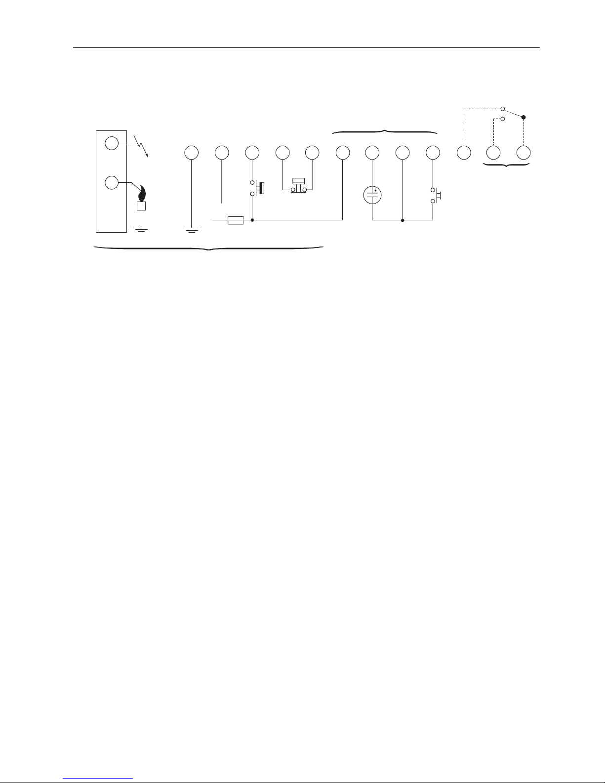
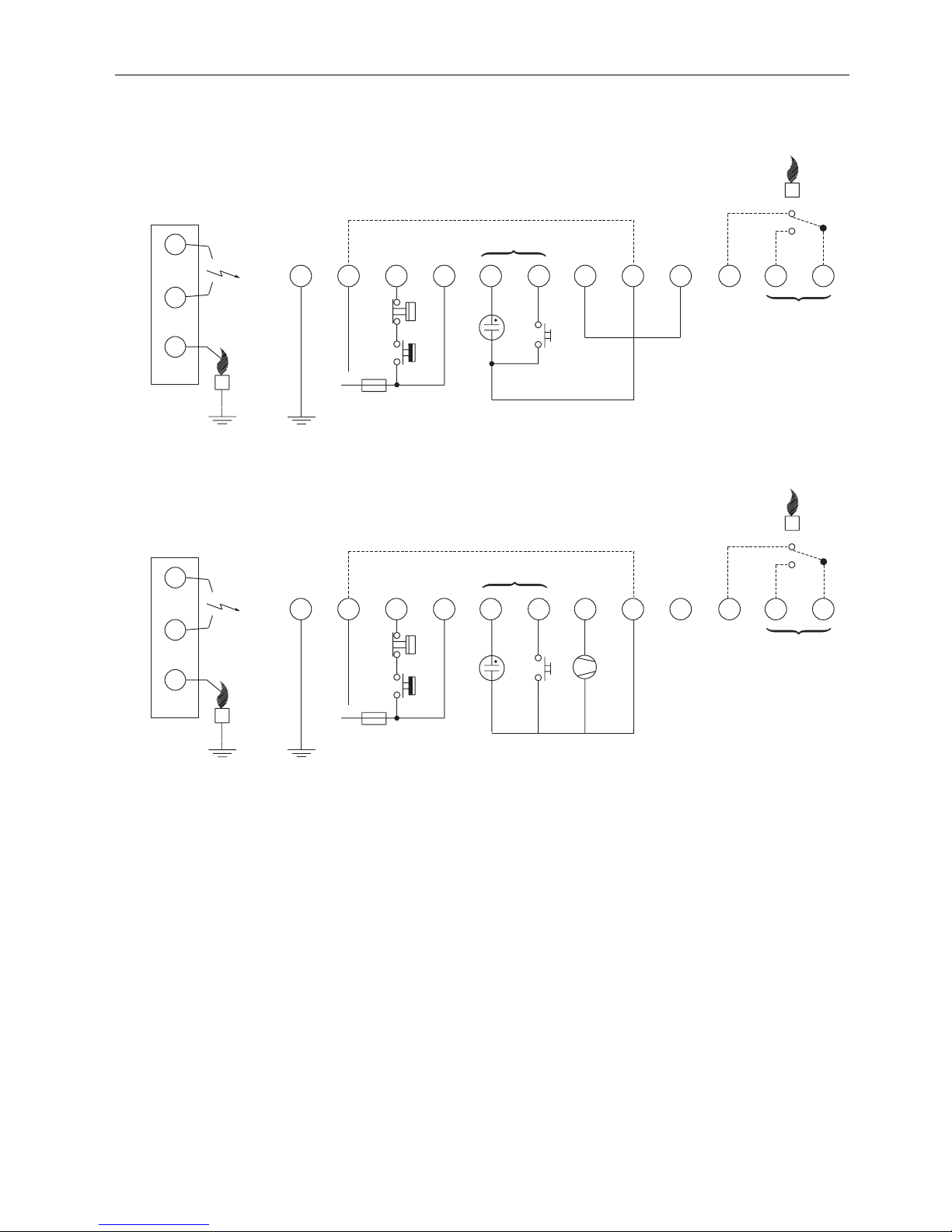
CONNECTION DIAGRAM S4565A, B ,P, Q
Fig. 6. Connection diagram S4565A, B, P and Q
Side connections
N
L
Optional **
LM
RS
Optional
Optional
All versions
*
12
11
10
9
8
76 5
4
3
21
* See note 3.
** See page 21. Fig. 19.

EN2R-9031 0402R15-NE 12
SYSTEM OPERATION S4565A, B, P, Q
General
Lock-out reset
The S4565A, B, P and Q ignition controls can be reset by
either depressing the internal/external reset button (suffix A
and B) or by interrupting the permanent live connection
(suffix P and Q).
If a first reset is not succesful, wait at least 15 seconds before
attempting another one.
NOTE 1.: When first starting, the ignition control can be in
the lock-out condition; depress the reset button
to free the ignition control. After a manual reset
an extended prepurge/waiting time will occur.
NOTE 2.: If during normal use the reset button is pressed,
the gas valves drop out and the ignition control
starts a new sequence after releasing the reset
button.
NOTE 3.: If permanent alarm output: neon indicator with
integral resistor >150 kΩ (max 1 mA)
NOTE 4.: If an automatic return high limit thermostat is
used, the high limit switch in the application
needs a longer return time than the trial for ignition time of the ignition control. This in order to
provide non volatile lock out.
Suffix A, B, P and Q (see Fig. 7.)
When there is a call for heat a self check period (Tc) plus
waiting period (T
w
) elapse before built-in igniter and gas valve
are switched on.
The ignition spark ignites gas and resulting flame is detected
by the flame rod.
Ignition is switched off after extended ignition time and flame
establishment.
If flame is not established within the safety time (T
s
), the
ignition control locks out.
If the flame is lost during normal run, the ignition control
repeats the start sequence.
13 EN2R-9031 0402R15-NE
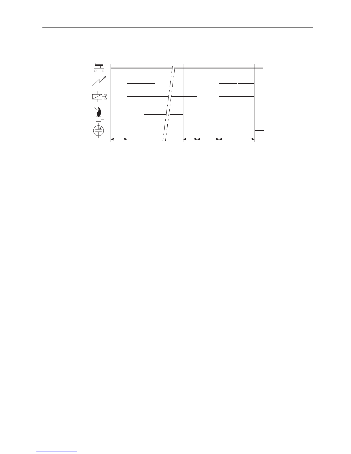
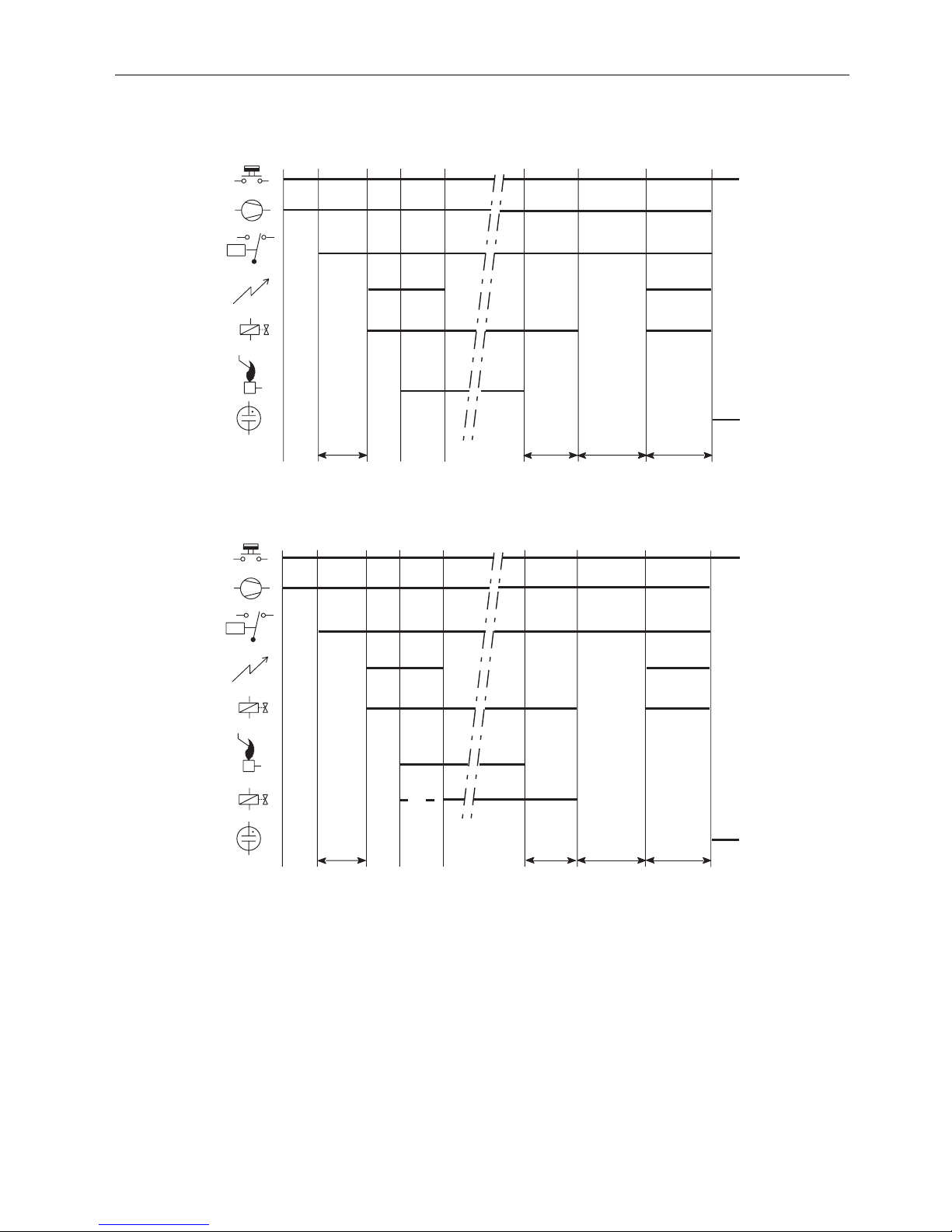
TIMING DIAGRAM S4565A, B, P, Q
Fig. 7. Timing diagram S4565A, B, P and Q
Tc+Tw TsTc+TwTFR

EN2R-9031 0402R15-NE 14
SPECIFICATIONS S4565C, D, R, T
Model
Suffix C: fan assisted, direct burner ignition
Suffix D: fan assisted, intermittent pilot burner ignition
including safety timer
Suffix R: as C except volatile lock-out
Suffix T: as D except volatile lock-out
Supply voltage
220 ... 240 Vac, 50/60Hz (-15%, +10%)
Power consumption
4 VA
Humidity
90% RH max. at 40°C
Ambient temperature
-15 ... 60°C
Electrical rating (see also note 7.)
Alarm: 220 ... 240 Vac, 50/60Hz, 1 A,
cos ϕ > 0.6 or max 1 mA
Fan: 220 ... 240 Vac, 50/60Hz, 1 A,
cos ϕ > 0.6
LPG outdoor valve: 220 ... 240 Vac, 50/60Hz, 1 A,
cos ϕ > 0.6
External ignition transformer: 220 ... 240 Vac, 50/60Hz,
1 A, cos ϕ > 0.6
Electrical connection
High voltage spark: 2.8 x 0.5 mm spade terminal
Optional: External mains voltage ignition
transformer
2.8 x 0.5 mm spade terminal
Flame sensing: 4.8 x 0.8 mm spade terminal or 2.8 x
0.5 mm spade terminal for combined
high voltage spark/flame sensing
PCB connectors: Molex 3003 series suitable for
Molex 3001 female cable connector
Housing (degree of protection)
See:
accessories for degree of protection page 7..
replacement parts and accessories page 66..
Timing (depending on O.S. number)
Self check time (T
c
): 0, 1.5 or 2 s
Prepurge time (Tp): 0 ... 30 s
Safety time (Ts): 3.5 ...55 s
Extended spark ignition
time and stabilisation time: 0 ... T
s
(depending on elaps of safety time)
Flame sensing
Min flame current: 0.9 µA
Response time on: > 0.2 s
Response time off (T
FR
): < 1 s
(optionally other values available)
Ignition
Spark voltage: > 12 kV at 40 pF load
(depending on O.S. number)
Spark energy: 3 ... 15 µAs
Repetition rate: 2.5 ... 60 Hz
(depending on O.S. number)
Max spark gap: 3.5 mm
Length flame sensing cable
1 m max.
Length ignition cable
0.5 m max.
Length of wiring for external components
1 m max.
15 EN2R-9031 0402R15-NE
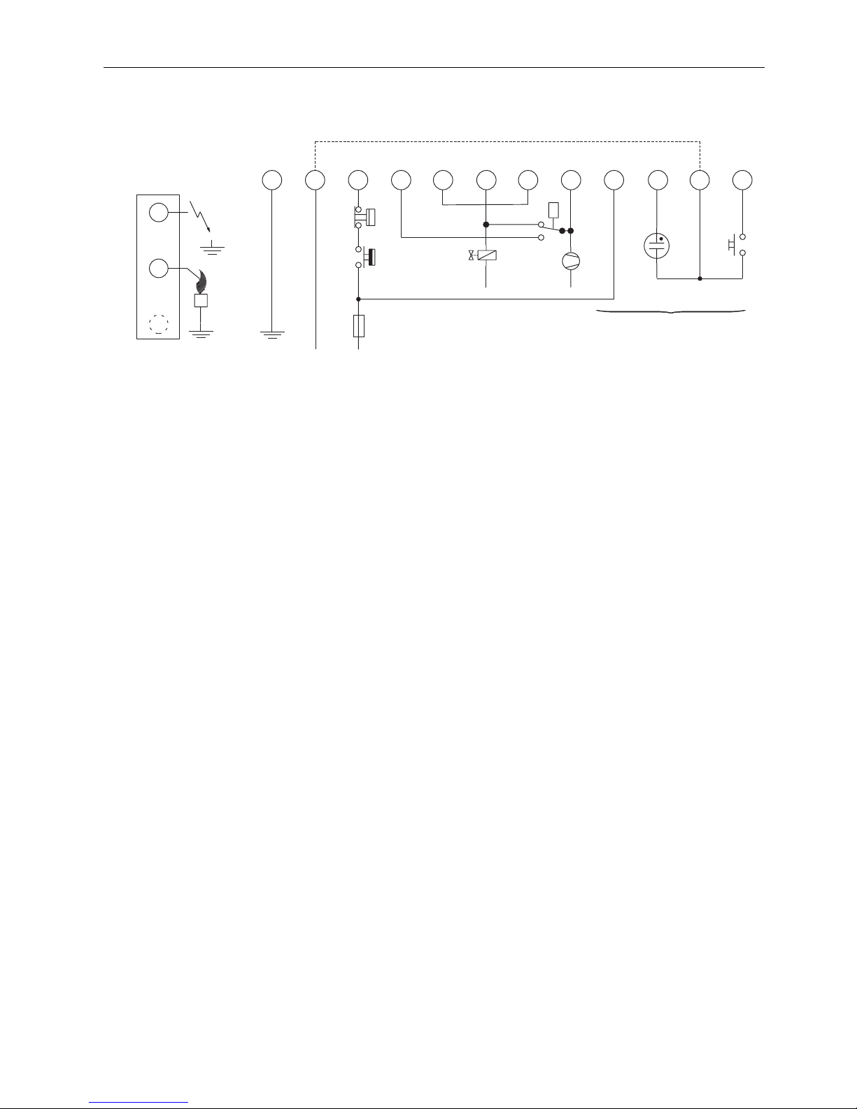
CONNECTION DIAGRAM S4565C, D, R, T
Fig. 8. Connection diagram S4565C, D, R and T
P
LN
Side connections**
LM
RS
Optional
*
N
LPG
N
10
3
7
1
11
8
24
569
12
* See note 7.
** Alternative side connection for models with combined flame de-
tection/high voltage. See page 56. Fig. 71.

EN2R-9031 0402R15-NE 16
SYSTEM OPERATION S4565C, D, R, T
General
Lock-out reset
The S4565C, D, R, T ignition controls can be reset by either
depressing the internal/external reset button (suffix C and D)
or by interrupting the permanent life (suffix R, and T).
If a first reset is not succesful, wait at least 15 seconds before
attempting another one.
NOTE 5.: When first starting, the ignition control can be in
the lock-out condition, depress the reset button
to free the ignition control. After a reset an
extended waiting time will occur.
NOTE 6.: If during normal use the reset button is pressed,
the gas valves close and the ignition control
starts a new sequence after releasing the reset
button.
NOTE 7.: If permanent alarm output:neon indicator with
integral resistor >150 kΩ (max 1 mA)
Suffix C and R (see Fig. 9.)
When there is a call for heat the fan starts running through
the no air position of the air proving switch.
If an external LPG valve is connected, this will be energized.
When sufficient air flow is proven by the air proving switch, a
self check period (T
c
) plus a prepurge period (Tp) elapse
before the gas valve and built-in ignition or external ignition
transformer (optional) are switched on.
The ignition spark ignites gas and resulting flame is detected
by the flame rod.
Internal or external ignition is switched off.
After flame establishment a predetermined, extended ignition
time can be included.
If flame is not established within the safety time (T
s
), the
ignition control locks out.
If the flame is lost during normal run, the ignition control
repeats the start sequence with prepurge.
If no air is proven by the air proving switch within the
prepurge time (T
p
), the ignition control stays in waiting mode
with fan running.
Suffix D and T (see Fig. 10.)
When there is a call for heat the fan starts running through
the no air position of the air proving switch.
If an external LPG valve is connected, this will be energized.
When sufficient air flow is proven by the air proving switch, a
a self check period (T
c
) plus a prepurge period (Tp ) elapse
before the pilot gas valve and built-in ignition or external
ignition transformer (optional) are switched on.
The ignition spark ignites pilot gas and resulting flame is
detected by the flame rod.
Internal or external ignition is switched off.
After flame establishment a predetermined, extended ignition
time can be included.
If flame is not established within the safety time (T
s
), the
ignition control locks-out.
If the flame is lost during normal run, the ignition control
repeats start sequence at prepurge.
If no air is proven by the air proving switch within the
prepurge time (T
p
), the ignition control stays in waiting mode
with fan running.
WARNING
Do not interchange air proving switch wiring in order
to prevent malfunctioning
17 EN2R-9031 0402R15-NE
TIMING DIAGRAM S4565C, D, R, T
Fig. 9. Timing diagram S4565C and R
Fig. 10. Timing diagram S4565D and T
T
c + Tp
P
T
s
T
c + Tp
T
FR
T
c + Tp
P
T
s
PV
MV
T
c + Tp
T
FR

EN2R-9031 0402R15-NE 18
SPECIFICATIONS S4565AD, BD, CD, DD, PD, QD, RD, TD “1000” SERIES
Model
Suffix AD: atmospheric, direct burner ignition
Suffix BD: as AD but with flame relay output
Suffix CD: fan assisted, direct burner ignition
Suffix DD: as CD but with flame relay output
Suffix PD: as AD except volatile lock-out
Suffix QD: as BD except volatile lock-out
Suffix RD: as CD except volatile lock-out
Suffix TD: as DD except volatile lock-out
Supply voltage
220 ... 240 Vac, 50/60Hz (-15%, +10%)
Power consumption
4 VA
Humidity
90% RH max. at 40°C non condensing
Storage
- 30 ... 70°C
Ambient temperature
-15 ... 60°C
Electrical rating (see also note 10.)
Alarm: 220 ... 240 Vac, 50/60Hz, 1 A,
cos ϕ > 0.6 or max 1 mA
Fan: 220 ... 240 Vac, 50/60Hz, 1 A,
cos ϕ > 0.6
Flame relay contact: 220 ... 240 Vac, 50/60Hz,1 A,
cos ϕ > 0.6
Flame opto coupler: +5 V, 10 kΩ
LPG valve: 220 ... 240 Vac, 50/60 Hz, 1 A max,
cos ϕ > 0.6
Electrical connection
High voltage spark: 2.8 x 0.5 mm spade terminal
Flame sensing: 4.8 x 0.8 mm spade terminal
PCB connectors: Molex 3003 series suitable for
Molex 3001 female cable connector
Housing (degree of protection)
See:
accessories for degree of protection page 7..
replacement parts and accessories page 66..
Timing (depending on O.S. number)
Self check time (T
c
): 1.5 s
Waiting time (Tw): 0 ... 30 s
Safety time (Ts): 3.5 ... 25 s
Extended spark ignition time: 0 ... T
s
(depending on elaps of safety time)
Flame sensing
Min flame current: 0.9 µA
Response time on: > 0.2 s
Response time off (TFR): < 1 s
Ignition
Spark voltage: > 12 kV at 40 pF load
(depending on O.S. number)
Spark energy: 3 ... 15 µAs
Repetition rate: 2.5 ... 60 Hz
(depending on O.S. number)
Max. spark gap: 3.5 mm
Optional external ignition circuit:220 ... 240 V (at no load),
single phase rectified,
max 2 VA
Length flame sensing cable
1 m max.
Length ignition cable
0.5 m max.
Length of wiring for external components
1 m max.
Remark
Optional integrated flame relay available with safe separation
or opto coupler with safe separation.
N.C. contact of flame relay has no safe separation.
WARNING
Opto coupler interface needs a debounce time > 20
ms in order to prevent noise caused by transients on
mains.
19 EN2R-9031 0402R15-NE
CONNECTION DIAGRAM S4565AD, BD, CD, DD, PD, QD, RD, TD “1000“ SERIES
Fig. 11. Connection diagram S4565AD and BD “1000” series
Fig. 12. Connection diagram S4565BD and QD “1000” series for gas/air application
L
N
LM
Optional
RS
Side connections **
*
Optional ***
Optional
12
11
10
9
8
76 5
4
3
21
* See note 10.
** See page 21. Fig. 17.
*** See page 21. Fig. 19.
L
N
LM
Optional
RS
Side connections **
*
Optional ***
Optional
12
11
10
9
8
76 5
4
3
21
* See note 10.
** See page 21. Fig. 17.
*** See page 21. Fig. 19.
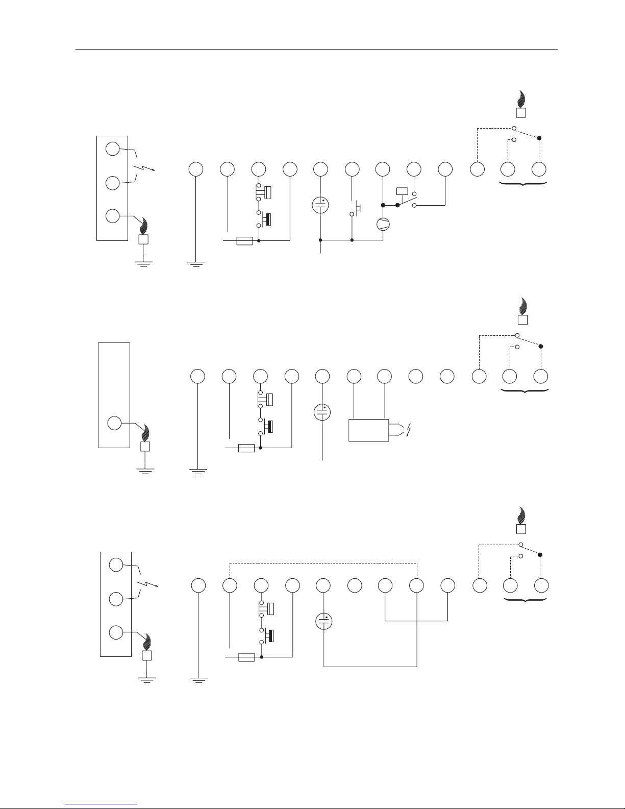
EN2R-9031 0402R15-NE 20
Fig. 13. Connection diagram S4565CD and DD “1000” series
Fig. 14. Connection diagram S4565QD “1000” series with external ignition circuit
Fig. 15. Connection diagram S4565PD and QD “1000” series
L
N
LM
Optional
RS
N
P
Side connections **
*
NC
NO
C
Optional ***
12
11
10
9
8
76 5
4
3
21
* See note 10.
** See page 21. Fig. 17.
*** See page 21. Fig. 19.
12
11
10
9
8
76 5
4
3
21
L
N
LM
N
Side connections
*
+-
Optional ***Optional
* See note 10.
*** See page 21. Fig. 19.
12
11
10
9
8
76 5
4
3
21
N
L
LM
Optional
Side connections **
*
Optional ***
* See note 10.
** See page 21. Fig. 17.
*** See page 21. Fig. 19.
 Loading...