

INSTRUCTION SHEET
S4567A 1001 & S4567B 1017
IGNITION CONTROL FOR COMBINED VALVE AND IGNITION SYSTEM
EN1R--9132 0011R7--NE
APPLICATION
The Combined Valve and Ignition system (CVI) has specially
been developed for application in gas fired appliances with
either intermittent pilot or direct burner ignition.
For this system, the S4567A 1001 and S4567B 1017 ignition
controls have been designed to attach directly onto the
VK4105 gas controls.
The combined system then provides programmed s afe light
up, flame supervision and regulation of gas flow to the main
burner.
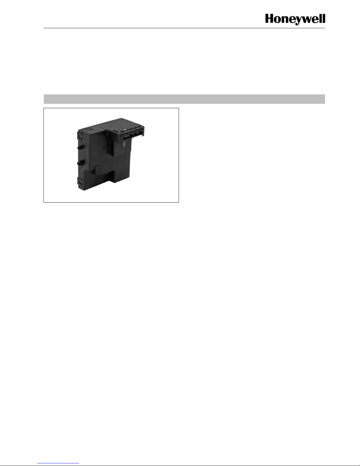
DESCRIPTION
The S4567A 1001 and S4567B 1017 ignition controls provide
automatic ignition for direct gas burner applications.
The S4567A 1001 and S4567B 1017 ignition controls comply
with EN 55014 and function in accordance with:
-- EN 298, code A/M/C/L/X/N.
-- ANSI Z21.20
FEATURES
Flame supervision.
Built in 33 Hz or 40 Hz ignition.
External reset and alarm.
Accurate safety timer.
Supply voltages of 220 ... 240 V in a single product.
Full operating sequence after flame loss.
Safe separation opto couplers for flame output
(S4567B 1017 only), alarm output and reset input.
Non volatile lock --out according EN 298.
Gas valve live output (S4567A 1001 only).
Flame rod safely accessible because of protective
impedance.
SPECIFICATIONS
Model
S4567A 1001 ignition control for atmospheric, direct
burner ignition.
S4567B 1017 ignition control for atmospheric, direct
burner ignition and flame opto output
Supply voltage
220 ... 240 Vac, 50 ... 60 Hz
Power consumption
4VA
Humidity
90% RH max. at 40 _C (non condensing)
Ambient temperature
--15 ... 60 _C
Electrical rating
Gas valve output (pin 2 of S4567A 1001): suitable for one
VK4105. Use rectifier plug from the 45.900.441--“series “,
e. g. 45.900.441 --030
Electrical connection
High voltage spark: 2.8 x 0.5 mm spade terminal
Flame sensing: 4.8 x 0.8 mm spade terminal
PCB connector: Stocko mks 2823 3 and 4 pole
IP protection degree in accordance with EN 60529
IP 00 (standard)
IP 04 or IP X4
Use: cover set 45.900.431--004 or
cover set 45.900.431 --005
(flame retardant according to UL94--V0)
cable grommet 45.900.442--008/009
sleeve 45.900.442--003
gasket 45.900.442--007/011
IP 44
As IP 04 but the appliance manufacturer must connect the
ignition output in such a way that it cannot be taken off
without the use of a tool.
In order to prevent the risk of an electric shock when the
ignition control is mounted in the appliance, additional
protection of the ignition output must be provided by the
application manufacturer in all above cases.
Timing
Self check time (T
c
): 1.5 s
Safety time (T
s
): 10 s
Flame sensing
Min. flame current: 0.9 ←A
Response time on: > 0.2 s
Response time off at I
flame
=2←A:< 1s
Subject to change without notice. Printed in the Netherlands.
2
EN1R--9132 0011R7--NE
Cable length
Flame sensing: 1000 mm max.
Ignition: 500 mm max.
Ignition
Spark voltage: > 15 kV at 40 pF load
Repetition rate: S4567A 1001: 40 Hz
S4567B 1017: 33 Hz
Spark energy: S4567A 1001: 9 ←As
S4567B 1017: 3 ←As
Max. spark gap: 3.5 mm
Remark
Integrated flame (S4567B 1017 only), alarm and reset opto
couplers with safe separation.
SYSTEM OPERATION
S4567A 1001 and S4567B 1017 (see fig. 3.)
When there is a call for heat a self check time (T
c
) plus waiting
period (T
w
) elapse before built--in igniter and gas valve(s) are
switched on.
The ignition spark ignites gas and resulting flame is detected
by the flame rod.
Ignition is switched off after extended ignition time and flame
establishment.
If flame is not established within the safety time (T
s
), the
ignition control locks out.
If the flame is lost during normal run, the ignition control
repeats start sequence.
Lock- out reset
The ignition control can be reset by depressing the external
reset button.
If a first reset is not succesful, wait at least 15 seconds before
attempting another one.
NOTE 1.: When first starting, the control can be in the
lock--out condition; depress the reset button to free
the controls.
After a manual reset an extended waiting time will
occur.
NOTE 2.: If during normal use the reset button is pressed, the
gas valves drop off and the ignition control starts a
new sequence after releasing the reset button.
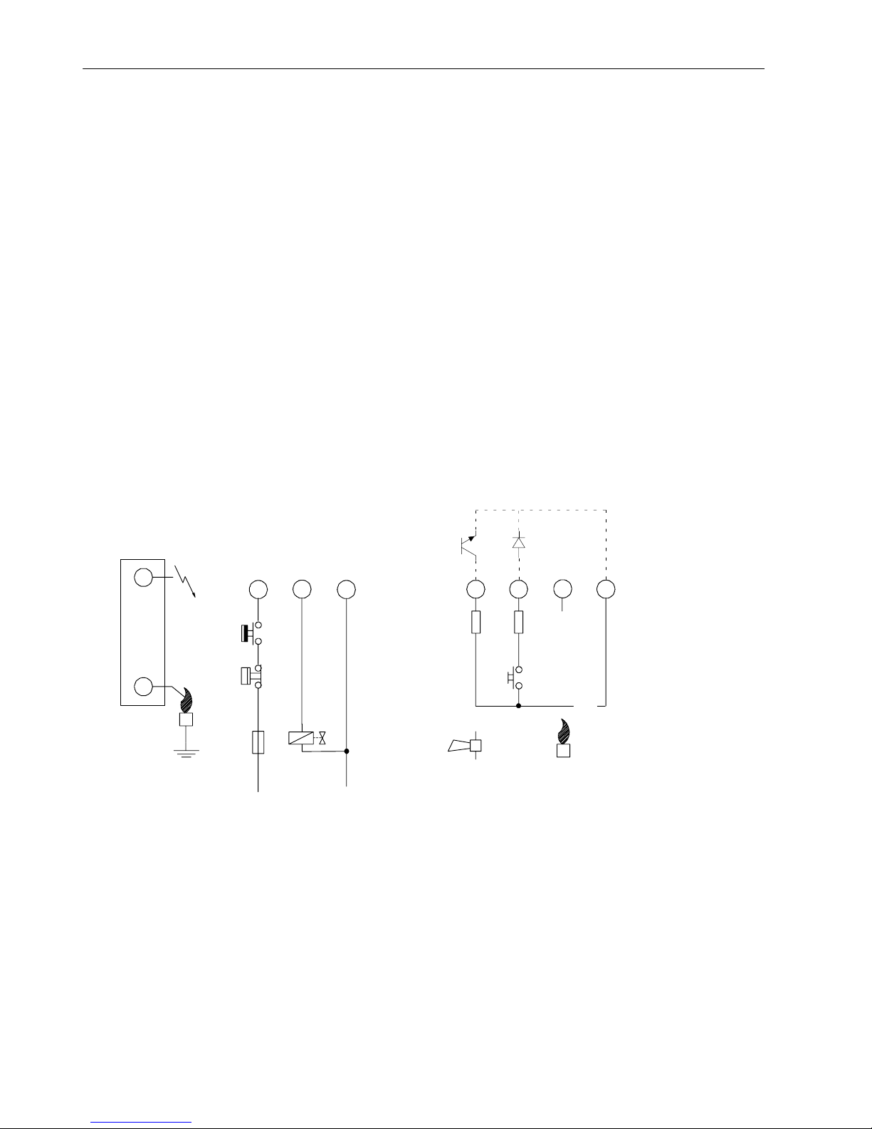
Side connection
45
L
3
31
RS
62
LM
N
10K 1K
+ --
5V
LM -- Limiter
RS -- Reset switch
GV -- Gas valve
GV
Fig. 1. Connection diagram S4567A 1001
 Loading...