

Page 1
RP92OD
RP920A-D
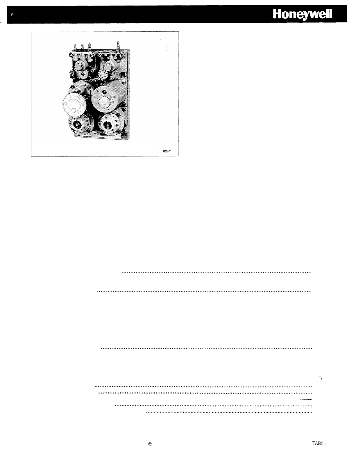
Modular Pneumatic
Controller
Service Data
TABLE OF CONTENTS
GENERAL
Description
Application
Specifications
Operation ......................................................................................................................................
RP920A
RP920B
MAINTENANCE..
Equipment Required
Inspection and Cleaning
Operational Check
All Systems
System in Operation
System not Operating-Sensors Disconnected
Calibration Check..
Calibration ....................................................................................................................................
Adjustments . . . . . . . . . . .
.......................................................................................................................................
....................................................................................................................................
...................................................................................................................................
................................................................................................................................
or C Controller..
or D Controller
........................................................................................................................
..........................................................................................................................
...............................................................................................................................
....................................................................................................................
Equipment
Pr0xdLu.e
Operating Point
Operating
S etpoint
Compensation Startpoint
RP920A
RP920B
RP920C
General
..............................................................................................................................
................................................................................................................................
(RP920A
Point
as
....................................................................................................................................
. . . . .
. . . . . .
. . . . . . . . . . . . . . . . . . . . . . . . . . . . . . . . . . . . . . . . . . . . . . . . . . . . . . . . . . . . . . . . . . . . . . . . . . . . . . . . . . . . . . . . . . . . . . . . . . . . . . . . . . . . . . .
and D
. . . . . . . . . . . . . . . . . . . . . . . . .
...............................................................................................................
...................................................................................................................
..................................................................................
and B)
Maximum
(RP920B
...................................................................................................
.......................................................................
Limit
and D)
(RP920C
.......................................................................................
D).
and
3
3
3
4
4
4
4
4
5
5
5
5
5
5
5
6
6
6
6
7
-7
9
9
9
Copyright 1993 Honeywell Inc. � All Rights Reserved
85-0142
MLF C. 6.
Page 2

TABLE OF CONTENTS (Continued)
Direct to Reverse Acting
Negative to Positive Compensation
Integral Action Cut-Off and Gage Function
Setpoint
Adjustment
Local Setpoint Adjustment
Remote
Setpoint
Adjustment
......““““““.““.““.“““.‘..“‘.““.
(RP920B
and D)
(RP92OC
..“““.“‘.“.“‘.““.““““‘.““““““.“““‘.““““.“‘.““‘.‘.‘..“..“..--.‘.
..““““““““““‘.““‘.‘.“.‘..““.“““‘....“*“‘.““.““..“““..“‘...‘*.‘..‘...“.
Control Point Adjustment (CPA Models Only)
Proportional Band Adjustment
Authority Adjustment
Compensation Startpoint Adjustment
Reset Time Adjustment
Cover
....*...“‘.‘....““..‘..“.“‘.‘...“..“‘.““.“..“.‘.“‘.““‘..“..‘..““.“.‘...*....“....‘.““..‘.“‘.‘..**.*.......‘...
TROUBLESHOOTING
(RP920B
and D)
(RP920B
(RP920C
and D)
..““.““““..““‘.“““““‘....“‘*‘.‘.‘.‘.‘.““““““..““....“.‘...f..
...*“‘...‘..‘.‘..“.‘.‘..“‘.“..“.“...‘
REPAIR... . . . . . . . . . . .
Module Replacement
Setpoint
Knob Replacement
..““.“““““...“........‘..“‘.‘
..‘..““““““.“‘..“‘.*“.“‘.‘.‘.“.“.“.“.““‘.‘
Filter/O-Ring Replacement in Connector Block Module
Gage Seal Replacement
PARTS AND ACCESSORIES
Parts List
Accessories
APPENDIX A
......““‘*....“‘*“““.“““““‘
..*“.“...‘.‘.“““‘..“““‘
..““..“.““.“.“.‘.“
..‘..‘.“.“.‘.“‘.“““...“‘.‘.“‘.“““‘...‘.‘.‘*“.‘.‘....‘.“.“‘..‘....‘.‘..“*‘.X‘.‘.....“.‘.‘..
..“.“.“‘.‘.“‘.“.‘.f*“
..“.“.“‘.‘.““.“.‘.‘......‘........*...
and D)
..“‘.“.“....“....t.“‘...
..““““..““.‘.“““‘.““.‘.‘.““*““.“““.‘..‘...*..tl.
..“““..““.““‘...‘n‘..“......‘f...s
..,‘.“““‘..“.‘...*..‘..
...‘.“‘..‘.*‘.“.““‘.“‘..‘.1..‘.‘.*..--...
and D)
..‘.“““..“.‘..“‘*.“.*..
....‘..*‘.““‘.‘.“.‘.“....‘.*...“‘
.
11
11
11
12
12
12
13
13
13
13
13
13
14
14
14
14
.
15
15
16
16
16
16
850142
ii
Page 3
GENERAL
DESCRIPTION
The RP920 Modular Pneumatic Controller, in
conjunction with remote sensors, provides Proportional
(P)
or Proportional Plus Integral (p + I) control of temperature,
humidity, pressure, or dewpoint in WAC systems.
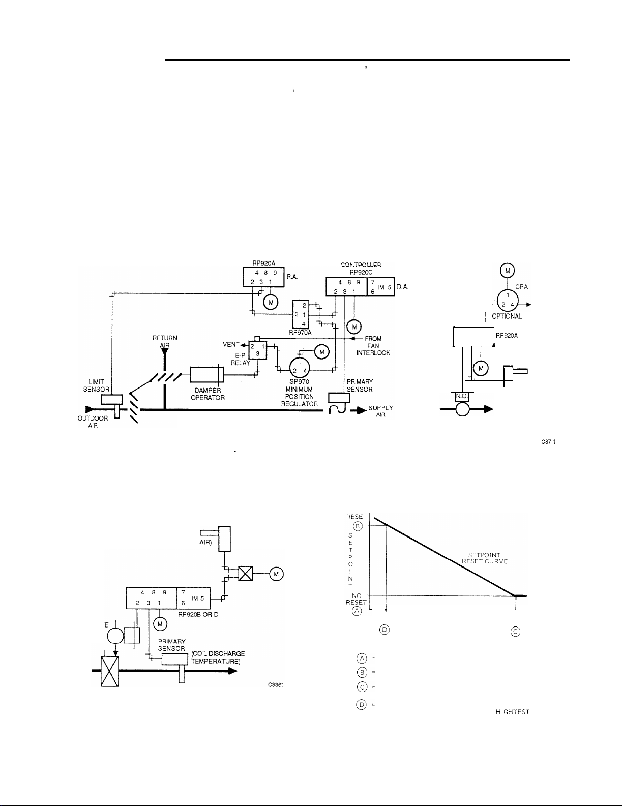
APPLICATION
In the mixed air control application (Fig.
sensor modulates the outdoor and return air dampers
MIXED AIR CONTROL SYSTEM
Fig. 1 Typical Single-Input Controller Applications.
l),
the primary
LIMIT
CONTROLLER
through the primary controller
(RP920C)
maintaining a
constant mixed air temperature. The limit controller
(RP920A)
and limit sensor sets outdoor air intake to a
minimum.
l),
In the hot water converter control application (Fig.
the
primary sensor modulates the steam valve on the converter
to maintain the hot water temperature. On CPA models the
hot water temperature can be adjusted remotely using a
gradual switch.
PRIMARY
M
CPA
1
2 4
4 8 9
2 3 1
r-l
STEAM
SUPPLY
HOT WATER CONVERTER
CONTROL SYSTEM
r
, MODELS ONLY
CPA
OR C
DA
PRIMARY
SENSOR
IN HWS
TO CONVERTER
LINE
In a dual-input control application (Fig.
2),
the RP920B
or D provides reset capability. Often, control of a building
is more efficient if the setpoint of the controller is reset to a
different value as a function of some parameter other than
COMPENSATION
SENSOR (OUTDOOR AIR)
VALV
N.O.
Fig, 2.
Typical
Dual-Input Control System.
the controlled variable, in this system, outdoor air
temperature. To use compensation, a reset schedule must be
set up (Fig. 3).
FULL
COMPENSATION
WHERE:
FULL
COMPENSATION SENSOR
LOWEST VALUE OF CONTROLLED VARIABLE.
HIGHEST VALUE OF CONTROLLED VARIABLE.
VALUE OF COMPENSATION VARIABLE WHEN
CONTROLLED VARIABLE IS AT ITS LOWEST VALUE.
VALUE OF COMPENSATION VARIABLE WHEN
CONTROLLED VARIABLE IS AT ITS
COMPENSATION
START
21365-l
Fig. 3. Compensation Reset Schedule.
3
VALUE.
85-O 142
Page 4

SPECIFICATIONS
OPERATION
Models:
RP920A:
RP920B:
RP920C:
RP920D:
Main Air Supply:
18
Minimum Air Pressure:
15
Maximum Safe Air Pressure:
30
Input Signal:
3
to 15 psi (21 to 103
Output Signal:
3
to 13 psi (21 to 90
Air Consumption:
RP920B
Sensor:
Air Capacity:
0.07
Single-Input Controller
Dual-Input Controller
Single-Input P + I Controller
Dual-Input P + I Controller
psi (124
psi (103
psi (207
pressure difference
kPa)
kPa)
kPa)
and
and D:
scfm
(33.0 ml/s) at
minimum
C:
kPa)
kPa)
scfm
0.021
scfm
0.046
0.019
scfm
sensor selected
18 psi
(9.9 ml/s)
(21.7 ml/s)
(9.0 ml/s) depending on
(124kPa) with 1
psi (7 kPa)
RP920A
the primary controller modulates the outdoor and return air
damper to maintain the mixed air temperature set on the
controller. As the outdoor temperature rises through the
narrow throttling range of the limit controller, the dampers
are gradually returned to the minimum position as set on the
minimum position switch. When the fan is off, the dampers
assume the normal positions.
primary sensor in the hot water supply
modulates the steam valve on the steam supply to the
converter to maintain the hot water temperature. As the
water temperature rises through the throttling range the
valve moves
change the control point temperature percent x the
sensor span.
RP920B
the primary sensor, located in the discharge air, is reset by
the compensation sensor in the outdoor air. Adjustments are
made on the controller to change the discharge air temperature according to a predetermined compensation reset
schedule (Fig. 3).
application because of the integral action.
OR C CONTROLLER
In the mixed air control system with high
In the hot water converter control system
from
from
open to closed. If the CPA is used, it can
OR D CONTROLLER
In the dual-input control system
The RP920D
(Fig.
2),
the
provides finer control in this
limit
(Fig. 1),
(Fig.
l), the
the converter
setpoint
of
Proportional Band:
2.5 to
50%,
field adjustable
Authority
5
Compensation Start Point
0
Integral Reset Time
0.5 to 20
Ambient Temperature:
40
(RP920B
to 300% of primary sensor span
to 100% of compensation sensor span
minutes, field adjustable
to 130F (5 to 55C)
and D Only):
(RP920B
(RP920C
and D Only):
and D Only):
MAINTENANCE
EQUIPMENT REQUIRED
1.
Gage 305965 (0-
2.
Gage Adaptor 729 with plug-in fittings.
3.
Receiver Gage to match primary
matic Indication, Receiver, and Target Gages Specification Data 77-6091).
4.
Barb Fitting 14003755-001 (integral models).
5.
Controller Calibration Kit
6.
Pneumatic Calibration Kit
to
30-psi).
MQP8
sensor
16A,
(see Pneu-
85-0142
Page 5
INSPECTION AND CLEANING
Occasionally, check for leaks and loose fittings and
screws. Especially check the self-tapping screw in Port 8
and the self-tapping screw at the top of the integral module
(RP920C
NOTE: Once removed, self-tapping screws can be a
or dirt from th e RP920.
and
D).
source of air leakage because of a damaged
0-
ring. Check the O-ring and replace it if it is
damaged,
Use a soft cloth or brush to remove accumulated dust and/
of the throttling range as set by the authority and
compensation startpoint. If a discrepancy exists,
recalibrate the controller.
Move th e setpoin t slightly up and down. The BLP
4.
should change proportionally in the same direction
for direct acting and in the opposite direction for
reverse acting controllers. Repeat this step using the
CPA if applicable. If the BLP responds properly, the
controller is good. Return th esetpoin t and CPA to the
original settings,
NOTE: The
RP920C
or D should maintai ncontrol
closer to th e setpoin t or reset schedule than
the RP920 A or B because of the integral
action.
OPERATIONAL CHECK
ALL SYSTEMS
Be certain all adjustment settings and conditions are
correct. See job drawing s
of the adjustments available on each model.
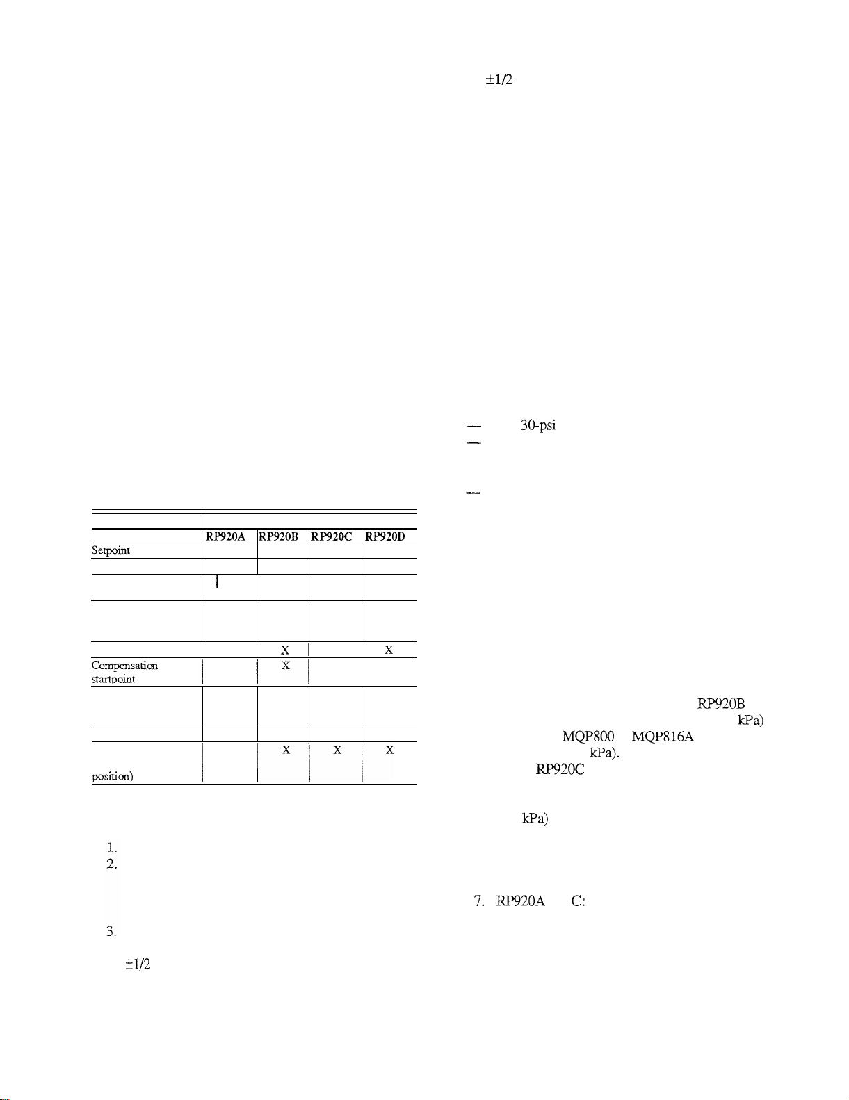
Table 1 . RP92 0 Adjustments.
Adjustment
Proportional Band
Internal restrictor
switch
Direct/reverse acting
(proportional
module position)
Authority
Positive/negative
compensation (switch
block module position
Reset time
Gage/integral cut-off
(switch block gasket
SYSTEM IN OPERATION
Be certain th e
Observe BLP. If it is not between 3 and 13 psi (21 to
90 kPa) , slowly adjust th e setpoin t knob and/or CPA
Allow the system to stabilize before continuing.
Measure the temperature, humidity, or static pressure
at the main sensor. This should agree with th e
of the
throttling range .
measurement should agree with the reset schedule
for
prope r
settings. Table 1 is a list
Model
X X X X
X X X X
X
I Xl X I X
X
I
HVAC
X X X
I I
X
X X
equipment is functional.
For
theRP920B andD
0 kPa ) range. until the BLP is in the 3 to 13 psi (21 to 9
setpoint
X
X
the
SYSTEM NOT OPERATING-SENSORS
DISCONNECTED
EQUIPMENT
0- to pressure gage.
Restricted air supply, adjustable from 3 to 15 psi (21
kPa) ,
to 10 3
with receiver gage to match sensors or
Sensor Controller Calibration Ki t MQP816A.
Pneumatic Calibration Kit MQP80 0 (optional).
PROCEDURE
1.
Connect the 0- t o30-psi gage to Port 2 (branch).
Connect the main air supply to Port 1 (18 psi
2.
minimum).
3.
Pipe a 3 to 15 psi (21 to 10
kPa ) adjustable air 3
supply with a receiver gage which matches the
primary sensor to Port 3.
4.
Pipe a second 3 to 15 psi (21 to 10
3kPa ) adjustable
air supply with a receiver gage which matches the
compensation sensor to Port 5 of an
5.
If checking a CPA model, pipe 9 psi to (62 to
Port 9. The
or can be used to
supply 9 psi (62
6.
On an and D, remove and save the seal
screw from the integral module (Fig. 12) and install
Barb Fitting 14003755-001 in its place. Apply 8 psi
(55
to the integral module. This prevents
integral action. Without this procedure, it is
necessary to allow additional time for the controller
to finish responding to any change in input pressure
or settings.
and
a .
Adjust the input air pressure to Por 3t to
correspond with the mid-point of the throttling
range of the primary sensor (see APPENDIX
A).
or D.
5
85-O 142
Page 6
b.
Set the
setpoint
knob to the percent of span,
temperature, or humidity that corresponds to the
input pressure. The BLP should be 8 psi (55
kPa).
If it is not correct, go to Step
8.
RP920B
a.
and D:
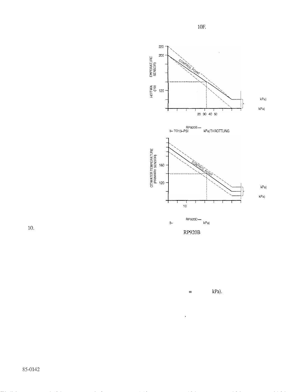
Plot the reset schedule to determine the
10.
corresponding compensation and primary
sensor values.
Convert the reset schedule value to pressure
b.
(See APPENDIX A) and adjust the air supplies
to those pressures. For an
should be 8 psi (55
kPa).
RP920D,
For an
the BLP
RP920B,
expected BLP depends on which point on the
reset schedule is being simulated. If BLP is not
within 1 psi of the control point pressure, go to
Step 10. Exact control point pressure can be
established for each application by constructing
a chart similar to that shown in Figure 4 and
referencing
APPENDIX
A.
If it is not correct, go
to Step 10.
9.
Move the
a,
kPa).
setpoint
knob until the BLP is 8 psi (55
Slowly increase the
setpoint
adjustment
one division The BLP should decrease
proportionally if the controller is direct acting or
increase proportionally if the controller is
reverse acting.
Slowly decrease the
b,
setpoint
one division. The
BLP should change proportionally in the
opposite direction of Step
For CPA models, repeat Steps 9a and 9b
c.
substituting the
If the controller works properly, go to Step 11. If
d.
CPA knob
9a,
for the
setpoint
knob.
the controller works properly, but is out of
calibration, go to Step 10.
To calibrate the controller:
a.
Adjust the
setpoint
knob until the correct BLP is
indicated on the gage.
b. Remove the
setpoint
knob. Replace it at the
correct setting without changing the
Return to Step 9.
Connect the tubing and make settings according to
11.
the job drawings.
the
BLP
Throttling range =
Proportional Band = 5 percent.
Setpoint = 1OOF
180
160
k-z@ 140
100
-10
220
200
180
140
I
100
-10 0 20 30 40 50 60 70
0
TO 13-PSI (21 TO 90 THROTTLING RANGE
(or 30 percent).
10 60 70
OUTDOOR AIR TEMPERATURE
(COMPENSATION SENSOR)
OUTDOOR AIR TEMPERATURE
(COMPENSATION SENSOR)
DIRECT ACTING
(21 TO 90 RANGE
DIRECT ACTING
13 PSI (90
THROTTLING RANGE
3 PSI (21
13 PSI (90
THROTTLING RANGE
3 PSI (21
c3337
Fig. 4. and D Reset Schedule,
Select (Fig. 4) any compensation sensor value (outdoor
temperature) within the compensation range, in this case
32F. Construct a line vertically to the control point line and
then horizontally to the left side. The hot water temperature
must be 140F to meet the reset schedule.
NOTE: On the
integral module with the seal screw. Be sure the
RP920C
and D, replace fitting in the
O-
ring is sealed
EXAMPLE:
The hot water temperature is reset from
100
to 200F as the
outdoor temperature goes from 60 to -l0F. The range of
the primary sensor is 40 to 240F and the compensation
sensor is
-40
to
16OF,
Additional settings taken from the
job drawings are:
Compensation startpoint = 60F (or
50
percent).
Compensation is negative.
Authority setting
=
157 percent.
From APPENDIX A the input pressures are:
Port 3 (primary) 9 psi (62
Port 5 (compensation) =
The BLP should be 8 psi (55
for
kPa)
NOTE:
RP920B
Previous discussion and illustration assumes 3 to
13 psi (21 to 90
7.3
psi (50.3
kPa) for RP920D,
kPa)
operating range. However,
the controller may be calibrated to match the
spring range of the actuator (e.g., 4 to
expected BLP at the would then be the
center of the actuator spring range (e.g., 7.5 psi).
6
kPa).
or 9 psi (62
11
psi). The
Page 7

CALIBRATION CHECK
TheRP920 is factory calibrated.
operate properly, check the calibration as follows,
OPERATING POINT (RP920A AND B)
1.
Pipe the connections (Fig. 5). Install Barb Fitting
14003755-001 in Port 8.
2.
Set the internal restriction to the blocked position.
Adjust the setpoint knob to 50 percent. On the
RP920B, adjust the compensation startpoint knob to
30 percent and set to negative compensation.
Adjust the proportional band to 50 percent and set for
3.
direct acting.
4.
If the BLP is 8 psi (55 kPa), go to Step 5.
the setpoint knob (Fig. 6) and turn the operating point
screw with a 5/64-inch Allen wrench until this value
is matched,
Reinstall the self-tapping screw in Port 8.
5.
If
the
controller
If
not, remove
does not
OPERATING POINT AS MAXIMUM LIMIT
(RP920C
1.
and D)
Pipe the connections (Fig.
7).
Install Barb Fitting
14003755-001 in Port 8 and in the top of the integral
module. Connect the mainline to the integral module.
This procedure requires 20 psi (138
kPa)
MLP_
2.
Adjust the setpoint to 50 percent. On the
adjust the compensation module to negative compensation and set the compensation startpoint to 30 percent.
3.
Adjust the proportional module to direct acting and
set the proportional band to 50 percent.
4.
Adjust the reset time to 15 minutes.
If the BLP is 17.5 psi (120 kPa), go to Step 6. If not,
5.
remove the setpoint knob and turn the operating point
screw with a 5/64-inch Allen wrench until this value
is matched.
Reinstall the self-tapping screws in Port 8 and in the
6.
top of the integral module.
minimum
RP920D
Fig. 5. Connections for Operating Point Check-RP920A
and B.
OPERATING POINT SCREW
MODULE
KNOB
Fig. 6. Operating Point Screw Location.
Fig. 7. Connections for Operating Point Check
and
SETPOINT
1.
Pipe the connections (Fig. 8). Install Barb Fitting
14003755-001 in Port 8.
2.
Apply
MLP.
Adjust the setpoint knob or screw until the gage
3.
reading is 9 psi (62 kPa).
4,
The setpoint knob setting should be 50
not, remove the setpoint knob and replace it oriented
to 50 percent.
5.
Reinstall the self tapping screw in Port 8.
(RP920C
percent. If
85-0142
Page 8

4 8 9
2 3 1
8. Connections for
009
ONLY
RP920 Setpoint
489 7
2 3
C, AND D
Check.
RP920A
If none exists, install a temporary receiver gage
(matching
sensor) or a 0- to
30-psi
primary sensor gage port.
2.
Apply MLP.
3.
Install a 0- to
4.
Adjust the
30-psi
setpoint
gage in the BLP test tap.
knob until the BLP equals the
centerpoint of the controlled device spring range.
5.
If the
setpoint
remove the
and primary sensor gage do not match,
setpoint
knob and replace it so the
matches the actual primary sensor gage reading.
6.
Readjust the
7.
Calibration is complete.
setpoint
to the desired setpoint.
gage in the
setpoint
COMPENSATION STARTPOINT
1.
Pipe the connections (Fig. 9).
2.
Apply
MLP-
Adjust the startpoint knob or screw until the gage
3.
indicates 9 psi (62
The
4.
setpoint
not, remove the
kPa).
knob setting should be 50 percent. If
setpoint
knob and replace it oriented
(RP920B
to 50 percent.
Fig. 9. Connections for
RP920B
and D Compensation
Startpoint Check.
CALIBRATION
and D)
RP920B
Supply the adjustable restricted air (equivalent to
Controller Calibration Kit
(primary sensor).
NOTE: Sensors are not connected.
Pipe a receiver gage matching the compensation
sensor, or a 0- to
RP920B.
NOTE: If the controller switch block module
If a BLP gage does exist, install a 0- to
in the branch line or in the BLP gage port if the
switch block gasket is in Position
4.
Apply MLP.
5.
Adjust the compensation startpoint knob until the
receiver gage indicates pressure equivalent of the
compensation startpoint (Fig. 10 and 11).
NOTE:
MQP816A)
30-psi
gage to Port 5 of the
to Port 3
gasket is in Position C, block Port 5 and
use the existing gage.
30-psi
gage
B.
Use APPENDIX A to find the equivalent
pressures for the temperature, humidity,
and percent of sensor span.
-THROTTLING
NOTE:
The following procedures can be used to calibrate
the RP920, or the
Calibration Kit can be used following procedures
in
CCT816B
Instructions 95-7 153
85-0142
MQP816A
Controller
Calibration Unit Installation
SENSOR
COMPENSATION
START POINT (WC)
Fig. Negative (Winter) Compensation Calibration
Reset Schedule, Direct Acting Controller-3 to 13 psi
Throttling Range.
8
Page 9

PRIMARY
SENSOR
COMPENSATION
START POINT (WC)
COMPENSATION
SENSOR
THROTTLING
RANGE
Fig. 11. Positive (Summer) Compensation Calibration
Reset Schedule, Direct Acting Controller-3 to 13 psi
(21 to 90
6.
Adjust the
the primary sensor at the compensation
kPa)
restrictor
Throttling Range.
for the equivalent pressure of
startpoint
on the reset schedule.
7.
Adjust the
setpoint
knob until the BLP equals the
desired BLP at the compensation start conditions
(e.g., 13 psi
[90
kPa]
for negative compensation, 3
psi for positive compensation).
8.
If needed, remove the
it so the
setpoint
at the compensation start. The
setpoint
knob and reposition
matches the primary sensor value
setpoint
knob is
calibrated.
Supply the adjustable restricted air (equivalent to
Controller Calibration Kit
MQP816A)
to Port 5
(compensation sensor).
10.
Adjust the
restrictors
for the equivalent pressure of
the sensors at full compensation on the schedule.
11.
Adjust the authority knob until the BLP equals the
desired pressure of the controlled device with full
compensation conditions.
NOTE:
This point can be slightly different from
the calculated authority set on the controller. Leave the new setting on the
controlIer
and mark the job drawings with the new
value.
12.
Calibration is complete.
RP920C AND D
1.
Remove and save the screw from the
RP92OC
integral module (Fig. 12) and install Barb Fitting
14003755-001 in its place.
2.
Apply 8 psi (55
3.
Calibrate the
the
RP920A.
procedures for the
When calibration is complete, remove the barb fitting
4.
kPa)
to the integral module.
RP92OC
following the procedures for
Calibrate the
RP920B.
RP920D
following the
and replace screw. Be certain that the O-ring is tight.
REMOVE SEAL
SCREW AND
INSTALL BARB
FITTING.
Fig.
ADJUSTMENTS
GENERAL
1.
Some adjustments on the
Controllers require removal of modules. Module and
port locations are shown in Figures 13 and 14.
2.
If a connection to Port 4, 6, or 7 is required, remove the
self-tapping screw from Port 8 and use the screw to tap
the port.
3.
Install Barb Fitting 14003755-001 and O-ring
tight in the appropriate port.
4.
If Port 8 is not used, reinstall the screw.
RP920
Modular Pneumatic
finger-
or D
9
85-0142
Page 10

I-MAIN I-MAIN
E-BRANCH
3-SENSOR
4-VENT
GAGE
PLUG
P-BRANCH
3-SENSOR
B-CLOSED
MODULE
VENT
BLOCK
MODULE
BRANCH GAGE
PORT
NTEGRAL
MODULE
PROPORTIONAL
MODULE
I-MAIN
‘J-PRIMARY
SENSOR
VENT
SENSOR
&CLOSED &CLOSED
PROPORTIONAL
MODULE
I-MAIN
2-BRANCH
3-PRIMARY
SENSOR
VENT
SENSOR
SWITCH
BLOCK
BRANCH GAGE
G
SWITCH
BLOCK
MODULE
COMPENSATION
SENSOR OR
BRANCHGAGE
PORT
NTEGRAL
MODULE
PROPORTIONAL
MODULE
COMPENSATION
‘ION
I
RP920
Fig. 13. Module and Port Locations.
10
Page 11

NEGATIVE TO POSITIVE COMPENSATION
(RP920B
and D)
Positive compensation is used for summer compensation
or humidity reset applications.
PROPORTIONA
ADJUSTMENT
Fig. 14. Adjustment Locations.
DIRECT TO REVERSE ACTING
1.
Loosen the four screws (Fig. 15) on the proportional
module.
2.
Remove the module. Rotate the module and its gasket
180 degrees and reinstall. Ensure that the notch on the
module lines up with the
proper indication on the
base.
Retighten the four screws.
3.
If required, recalibrate.
4.
PROPORTIONAL MODULE
CAPTIVE SCREWS
ADJUSTMENT
COMPENSATION
Loosen the four screws on the compensation module
(Fig. 16).
Remove the module. Rotate the module and its gasket
180 degrees and
reinstall.
Ensure that the notch on the
module lines up with the proper indication on the
base.
Retighten the four screws.
If required, recalibrate.
COMPENSATION MODULE
NEGATIVE COMP.
(FACTORY SET)
7 ’
NOTE LOCATION
OF NOTCH.
CAPTIVE SCREWS (4)
POSITIVE COMP.
Fig. 16. Changing from Negative to Positive
Compensation,
DIRECT REVERSE ACTING
NOTE LOCATION
0 F NOTCH
Fig. 15. Changing Controller Action
lNTEGRAl_
TION
11
ACTION CUT-OFF AND GAGE FUNC-
(RP920C
1.
Check the position of the gasket tab (Fig. 17). The
and
D)
position of the gasket located under the switch block
module determines the function of the field-installed
gage on the switch block module and determines if the
integral action cut-off function is enabled or disabled,
See Table 2 for factory and field settings.
Table
2.
Switch Block Module Gasket Position.
RP920B
RP920C
RP920D
B
B
B
C
C,
B = Branch Line Gage
C = Compensation Sensor Gage
= Action Cut-Off
Enabled
85-O
142
Page 12

Loosen the three screws securing the switch block
module and remove the module. Remove the gasket
and note the symbols embossed on the back of the
module (Fig 17).
3.
Rotate and/or flip the gasket until the gasket position
matches the functions desired with the desired letter
showing from the back of the module.
Reinstall the switch block module and tighten the
4.
three screws.
Connect the integral action cut-off switching
5.
components in Ports 6 and 7, if used
BLOCK MODULE
GASKET
TAB
POSITION
C.
Control Point Adjustment (CPA models only)--Thd baseline
setpoint
on the controller can be
adjusted percent of the primary sensor span
from a remote 3 to
4
15 psi (21
to 103kPa)signalinto
F-RON-T-
GASKET SHOWN IN C POSITION. AND ARE ALSO
SHOWN HERE FOR LOCATION.
Fig.
17. Integral Action Cut-Off and Gage Function
Gasket Position
SETPOINT ADJUSTMENT
1.
The
setpoint
knob Fig
18)
is embossed with a
to loo-percent scale. Scaleplate overlays are included
to match various sensor ranges.
2.
Three methods of
a, Local
setpoint
Setpoint
adjustment are available:
Adjustment-The
setpoint
adjusted directly on the controller.
b.
Remote
Setpoint
Adjustment-The
setpoint
controlled from 0 to 100 percent of primary sensor
span from a remote 3 to 15 psi (21 to 103
bleed-type switch or controller feeding Port 8.
Restricted air is supplied to Port 8 by the
controller.
NOTE:
Remote adjustment can be either Remote
Setpoint
Adjustment or CPA but not
both.
O-
is
is
kPa)
Fig.
18.
Setpoint
LOCAL SETPOINT ADJUSTMENT
See preceding
Adjustment.
2a.
If the scale overlay is used, insert the overlay between
the knob and transparent overlay retainer_
Note the position of the key and notch.
Using the
setpoint
knob, adjust the
setpoint
according
to the job drawings,
Calibrate only if the control point deviates
3.
significantly from the setpoint, taking into
consideration the throttling range.
REMOTE SETPOINT ADJUSTMENT
See preceding NOTE
1.
Adjust the
2b,
setpoint
knob to 100 percent or to the
maximum desired.
2,
Install Barb Fitting
connect to a bleed-type remote
SP970)
and 0- to
14003755-001
30-psi
gage,
to Port 8 and
setpoint
device (e.g.,
85-0142
12
Page 13

CONTROL POINT ADJUSTMENT (CPA Models Only)
1.
Pipe the CPA device to Port 9.
NOTE: A 1 psi change in the CPA pressure causes a
change of 2.5 percent of the primary sensor
span.
2.
Set the CPA to the center of its range when calibrating
controllers. For example: Set the CPA to 9 psi (62
for a 3-to
PROPORTIONAL BAND ADJUSTMENT
Adjust the Proportional Band
15-psi
(21 to 103
kPa)
signal range.
(PB)
according to the job
kPa)
drawings with the proportional band adjustment knob (Fig.
14).
PB =
Operating Throttling Range
Primary Sensor Span
COMPENSATION STARTPOINT ADJUSTMENT (RP920B and
D)
Adjust the compensation startpoint according to the job
drawings with the compensation startpoint adjustment
knob (Fig. 14). If the startpoint is not in percent, convert it
to a percentage of the compensation sensor range. See
APPENDIX A.
RESET TIME ADJUSTMENT (RP920C and D)
Adjust the reset time according to the job drawings
the
reset time adjustment knob (Fig, 14). When the system
with
is in operation and stable, decrease the setting a little at a
time
until
the system becomes unstable. Increase the setting
slightly until the system becomes stable.
COVER
AUTHORITY ADJUSTMENT (RP920B and D)
Adjust the authority according to the job drawings with
the authority adjustment knob
(Fig.
14). Calculate the
authority setting as follows:
Negative compensation:
ASC
Positive compensation:
A C x
Where (in measured variable units):
A C =
ASC =
scs =
ASP =
SPs
Authority
Compensation sensor operating range
Compensation sensor span
Primary sensor operating range
Primary sensor span
Throttling range in measured variable (use 0
RP920D)
for
If the authority is greater than 300 percent or
must be calculated using pressure units, see
RP920A-D
Modular Pneumatic Controller
Engineering Data 77-6082.
NOTE: Calibration can cause the actual
authority setting to vary from the
calculated value.
a cover is used, snap it straight on from the front. The
cover is secured by tightening the self-tapping screw in the
lower right comer.
13 85-O 142
Page 14

TROUBLESHOOTING
Table 3 lists the problems and solutions in
troubleshooting in
RP920
Controller,
Table 3.
Problem
1. When
2.
3.
4.
10. No air is supplied to primary sensor (Port 3) with Replace connector block module.
11.
12. Air leaks at restrictor switch.
13. Controller produces unacceptable noise (high
setpoint
does not reach the minimum of 0.5 psi (3.5
maximum of 2 psi (14
BLP does not react properly or reacts too slowly.
Continuous bleed-off at Port 4.
Air leak at BLP test tap. Plug with 14002172-001 Gage Tap Repair Plug or
When authority setting is changed in both directions,
BLP does not change.
RP920B
Compensation startpoint cannot be changed by Recalibrate if needed.
adjustment of compensation startpoint knob.
restriction switch in the unblocked position.
Air
leaks at Port 3 with restriction switch in blocked
position.
frequency humming).
is changed in both directions, BLP
kPa)
below mainline pressure.
and D only:
RP920
Problem-Solution Chart.
Replace
kPa)
or
I
renlace connector block module.
Replace switch block module (with startpoint
Tighten restrictor switch screw or replace connector
block module.
Identify which prv is generating the noise by touching
the related adjustment knob or screw until noise changes.
If source is
setpoint
prv,
renlace switch block. If needed, recalibrate,
Solution
setpoint
module. If source is in compensation startpoint
module and recalibrate,
setpoint
or operating point prv, replace
prv).
REPAIR
The following repair procedures cover recommended
repair for the
SORIES section under PARTS LIST.
NOTE? Before doing any repair on the
MODULE REPLACEMENT
1. Remove the module to be replaced, including the
gasket, by loosening the screws
85-0142
RP920
as listed in the PARTS AND ACCES-
RP920,
system air and disconnect all tubing from
shut off
ports.
2.
Install the new gasket and secure the replacement
module to the base with the screws.
3.
Connect and turn on the system air. Perform the
operational check.
SETPOINT
Simply lift off the
new one (Fig.
14
KNOB REPLACEMENT
setpoint
knob and replace it with the
Page 15

FILTER/O-RING REPLACEMENT IN
CONNECTOR BLOCK MODULE
Loosen the four screws securing the connector block
module to the base (Fig. 19).
2.
Loosen the screw securing the restrictor switch until
the connector block module can be lifted from the
base.
3.
Remove the screw and restrictor switch (Fig. 20).
4.
Using a wire or large paper clip, push through the hole
(Fig. 20). The filter and O-ring will fall out.
5.
Install the new filter and O-ring.
6.
Secure the restrictor switch to the connector block
module with the knob on restrictor switch positioned
between the two stops.
7.
Secure the connector block module with the four
screws.
SCREWS(4)
RES
CONNECTOR
GAGE SEAL REPLACEMENT
Remove the gage or gage plug (Fig. 20) from the
connector block module or switch block module.
2.
Insert a wire or paper clip into the hole in the center of
gage seal and gently pry out the old seal.
3.
Insert the new seal, small end down. Use the point of
a ball point pen to seat the seal.
4.
Replace the gage or gage plug,
RESTRICTOR
SWITCH
GAGE PLUG
/--GAGE SEAL
I
BLP TEST TAP
19442-3
Fig. 19. Connector Block Module Parts Identity.
22879
Fig. 20. Filter/O-Ring, Gage Seal Replacement Diagram.
15
85-0142
Page 16

PARTS AND ACCESSORIES
PARTS LIST
Table 4.
14004276002
14004277-003
14004277-004
14004278-002
14004283-002
Includes Gage
14004283-003
14004533-001
14004533-002
43188083-002
43188059-001
14004290-002
43 187524-001
43915905-l 10
14001865-001
14002172-001
14003757-001
RP920
Parts List (Refer to Fig. 13).
Seal and Plug
ACCESSORIES
Add-On
1.
2.
Gage 305965 (0 to 30 psi).
Gage Adaptor 315161A with plug-in fittings.
3.
4.
Receiver Gage to match primary sensor (see
Pneumatic Indication, Receiver, and Target Gages
Specification Data 77-609
5.
Controller Calibration Kit
Barb
Fitting 14003755-001.
1).
816A.
APPENDIX A
Table 5. Sensor
Humidity Sensors
VaIue
to Pressure or Percent of Span Conversion Chart.
Cover (Clear Plastic):
6.
43188057-010-RP920A.
43188123-010--RP920B,
Temperature, humidity, dewpoint, and
7.
warmer
Static pressure
8.
Rail mounting bag assembly (25 sets) 14004322-001.
9.
setpoint
scales 14004267-001.
setpoint
C, and D.
cooler-
scales 14004267-002.
85-0142
16
Page 17

Page 18

Page 19

Page 20

Page 21

Page 22

UNITED STATES
ALABAMA
MOBILE
ALASKA
ALASKA
ARIZONA
PHOENIX
ARKANSAS
LITTLE ROCK
CALlFORNlA
IRVINE
LOSANGELES
SACRAMENTO
SAN DIEGO
SAN FRANClSCO
SAN JOSE
COLORADO
DENVER
CONNNECTICUT
HARTFORD
DELAWARE
FLORIDA
JACKSONVILLE
MIAMI
ORLANDO
TAMPA
GEORGIA
HAWAII
ILLINOIS
CHlCAGO DOWNTOWN
CHICAGO NORTH
CHICAGO SOUTH
ELGW
PEORlA
INDlANA
FORT WAYNE
21
INDIANAPOLIS
IOWA
DAVENPORT
DES MOINES
KANSAS
80014455546
KENTUCKY
LOUISIANA
BATON ROUGE
NEW ORLEANS
SHREVEPORT
MAINE
ME
MARYLAND
BALTlMORE
x247
MASSACHUSETTS
BOSTON
MICHIGAN
DETROIT
1
GRAND RAPIDS
61612474811
SAGINAW
92-8707
MINNESOTA
TWIN CITY
MlSSlSSlPPl
JACKSON
MISSOURI
KANSAS
ST.
LOUIS
NEBRASKA
OMAHA
NEVADA
LAS VEGAS
NORTHERN NEVADA
NEW HAMPSHIRE
NEW HAMPSHIRE
NEW JERSEY
MT.
LAUREL
WESTFIELD
201,2351245
NEW MEXICO
NEW YORK
ALBANY
BUFFALO
LONG
ROCHESTER
SYRACUSE
WHITE PLAINS
NORTH CAROLINA
CHARLOTTE
GREENSBORO
RALEIGH
NORTHDAKOTA TEXAS
FARGO
OHIO
AKRON
CLEVELAND
COLUMBUS
DAYTON
AUSTIN
51214751788
DALLAS
EL PASO
FORT WORTH
HOUSTON
aoam7-4757
SAN
UTAH
OKLAHOMA
SALT LAKE CITY
CITY
TULSA
OREGON
PORTLAND, OR
PENNSYLVANIA
HARRISBURG
21516668302
VALLEY FORGE
METRO
RHODE ISLAND
PROVIDENCE
SOUTH CAROLINA
SOUTHDAKOTA
TENNESSEE
MEMPHIS
193
NASHVILLE CASPER
61513853400
VIRGINIA
RICHMOND
ROANOKE
WASHINGTON
SEATTLE
SPOKANE
WASHINGTON, D.C.
WASHINGTON, D.C.
WEST
CHARLESTON
CLARKSBURG
WISCONSIN
APPLETON
MADISON
MlLWAUKEE
WYOMING
VIRGINIA
(WV)
(OH)
CANADA
ALBERTA MANITOBA NOVA SCOTIA
CALGARY
EDMONTON
BRITISH COLUMBIA
VICTORIA
Home and Building Control
Honeywell Inc. Honeywell Limited-Honeywell
Honeywell Plaza 740 Ellesmere Road
P.O. Box 524 Scarborough, Ontario
Minneapolis, MN
850142 MLF TAB: II. C. 6. Rev. 3-89
WINNIPEG
NEW BRUNSWICK
MONCTON
NEWFOUNDLAND
ST. JOHN’S
Home and Building Control
ONTARIO
LONDON
51916852010
51
NORTH YORK
Printed in USA
OTTAWA
SUDBURY
WWDSOR
QUEBEC
SAtNTE-FOY
41816888320
VERDUN
51417659355
SASKATCHEWAN
REGINA
SASKATOON
Honeywell
Helping You Control Your World
 Loading...