

Page 1
Modular Pneumatic Controllers
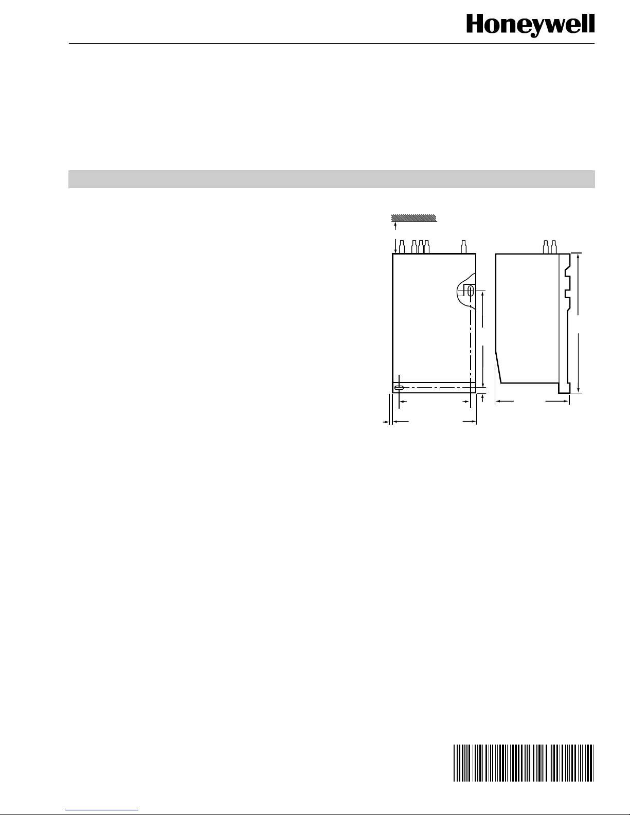
3 (75) MINIMUM CLEARANCE
4
(102)
3-3/8 (86)
9/32
(7)
RP920A: 1-1/2 (36)
RP920B-D: 3-1/4 (83)
5-7/8
(148)
1/8 (3)
MINIMUM
SPACING
BETWEEN
MODULES
RP920A: 1-7/8 (48)
RP920B-D: 3-13/16 (96)
M17581
INSTALLATION
Adjustments Before Mounting
1.
If a connection to port 4, 6, 7, or 8 (Fig. 2) is required,
remove the self-tapping screw from port 8 and use the
screw to tap the appropriate port.
2.
Install 14003755-001 Barb Fit ting and O-ring fing er-tight
in the appropriate port.
3.
Reinstall the screw in port 8 if not used.
4.
If a remote restriction is used for the primary sensor,
block the internal air supply (adjustable after gage
installation, but easier to adjust before installation):
a. Loosen the screw one turn (Fig. 3) and rotate the
switchplate (light grey) 90 degrees co unterclockwise
to the sensor supply blocked position.
b. Retighten the screw and check for leaks. If a leak is
found, reposition the switchplate.
RP920A,B,C,D
INSTALLATION INSTRUCTIONS
Device Mounting
1.
2.
Connections
1.
2.
NOTES:
— The switchplate screw mu st be tightene d securely
to prevent a false inoperative senso r condi tio n.
— The compensation sensor on port 5 requires an
external restricted main air supply.
Mark and drill two No. 8 fastener mounting holes using
the controller or Fig. 1 dimensions as a template.
Mount the controller with two No. 8 fasteners (not
supplied).
Push the tubing on the port barb fittings according to
the job drawings. See Fig. 2 for port locations.
Install the gage or plug:
a. If no gage is used, tighten gage plugs finger-tight.
If a gage is used, remove the plug and, by hand,
screw the gage into the gage port three turns.
b. If the gage is not oriented for correct viewing, rotate
the gage counterclockwise unti l corre ct.
NOTE: A soft-rubber, factory-installed seal allows
plug or gage rotation (for alignment) without
leakage.
Fig. 1. RP920 Dimensions in in. (mm).
After Mounting Adjustments and Changes
Controller Action Change
1.
Loosen the four Proportional Module screws (Fig. 4).
2.
Remove the module.
3.
Rotate the module and its gasket 180 degrees, and
reinstall. Ensure that the notch on the module lines up
with the proper indication on the controller label (base).
4.
Retighten the four screws.
5.
Recalibrate if required.
Negative (Winter) to Positive (Summer)
Compensation Change (RP920 B and D only)
1.
Loosen the four compensation module screws (Fig. 5).
2.
Remove the module.
3.
Rotate the module and its gasket 180 degrees, and
reinstall. Ensure that the notch on the module lines up
with the proper indication on the controller label (base).
4.
Retighten the four screws.
5.
Recalibrate, if required.
® U.S. Registered Trademark
Copyright © 2000 Honeywell • All Rights Reserved
95- 7392EF
Page 2
RP920A,B,C,D MODULAR PNEUMATIC CONTROLLERS
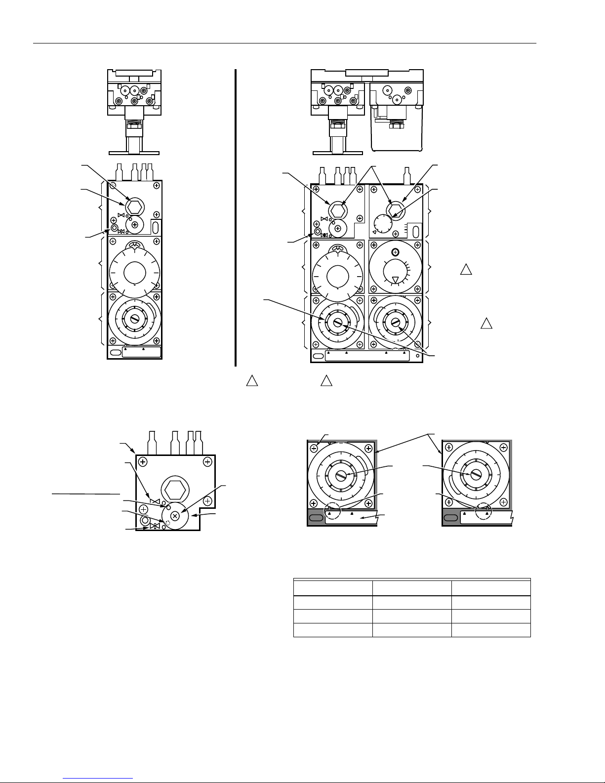
GAGE PLUG
PRIMARY SENSOR
GAGE PORT
Connector
Block Module
BLP TEST TAP
Setpoint
Module
Proportional
Module
RP920A
4 8 9
2 3 1
60
40
20
W
1
0
%
5
10
20
40
30
DIR.
REV.
RP920A
1 – MAIN
2 – BRANCH
3 – PRIMARY
SENSOR
132
4 – VENT
8 – CLOSED/REMOTE
SETPOINT
9 – CPA
80
100
Xp (%)
45
PRIMARY SENSOR
GAGE PORT
Connector
Block Module
BLP TEST TAP
Setpoint
Module
PROPORTIONAL
BAND ADJUSTMENT
KNOB
Proportional
Module
RP920B,C,D
4 8 9
32
2 3 1
60
40
20
W
1
0
%
5
10
20
40
30
DIR. REV.
100
Xp (%)
45
1
80
RP920D
7
GAGE
PLUGS
7 6 5
100
80
60
20
40
TR
0.5
1
300
Ac (%)
5
50
1 – MAIN
2 – BRANCH
5
6
Wc
%
0
B
+
C
+
B
C
Min
20
15
10
4
3
1.5
2
250
200
150
100
NEG.
POS.
3 – PRIMARY
SENSOR
4 – VENT
5 – COMPENSATION
SENSOR
6 – VENT
7 – VENT
8 – CLOSED/REMOTE
SETPOINT
9 – CPA
COMPENSATION SENSOR
OR BRANCH GAGE PORT
COMPENSATION STARTPOINT
ADJUSTMENT KNOB
Switch
Block
Module
Integral
7
Module
5
Compensation
Module
MODULE KNOB SCREWS
(DO NOT LOOSEN)
1
2
RP920C,D ONLY.
1
Fig. 2. Module and port Locations.
Connector
Block Module
SENSOR
SUPPLY OPEN
SWITCHPLATE
POSITION INDICATOR
2 3 1
SCREW
OPEN POSITION
BLOCKED POSITION
SENSOR SUPPLY BLOCKED
(EXTERNAL RESTRICTOR)
SWITCHPLATE
C5102
Fig. 3. Primary sensor air supply.
Gage Function and Integral Action Cut-off
Adjustment (RP920C and D)
The position of the gasket located under the switch block
module (Fig. 2) determines the function of the field-installed
Switch Block Module gage and enables/disables the integral
action cut-off function. See Table 1 for factory and field
settings.
RP920B,D ONLY.
2
CAPTIVE SCREW (4)
5
10
Xp (%)
20
45
40
30
DIR. REV. DIR. REV.
DO NOT
ADJUST
SCREW
NOTE LOCATION
OF NOTCH
CONTROLLER
LABEL
DIRECT ACTING
PROPORTIONAL MODULE
40
45
Xp (%)
5
REVERSE ACTING
Fig. 4. Changing controller action.
Table 1. Switch Block Gasket Position.
Model Field Setting
a
Options
RP920B B C
RP920C B B+
RP920D B C, C+, B+
a
Shipped from the factory in this position.
B = Branch line gage.
C = Compensation sensor gage.
+ = Integral action cut-off enabled.
M17584
30
20
10
C5103
95-7392EF 2
Page 3
CAPTIVE SCREW (4)
CAUTION
250
300
Ac (%)
5
50
100
POS.
NEG.
NEGATIVE COMP. (FACTORY SET)
200
150
DO NOT
ADJUST SCREW
COMPENSATION MODULE
NOTE
LOCATION
OF NOTCH
100
150
200
250
POS.NEG.
POSITIVE COMP.
50
5
Ac (%)
300
C5104
Fig. 5. Changing from negative to positive compensation.
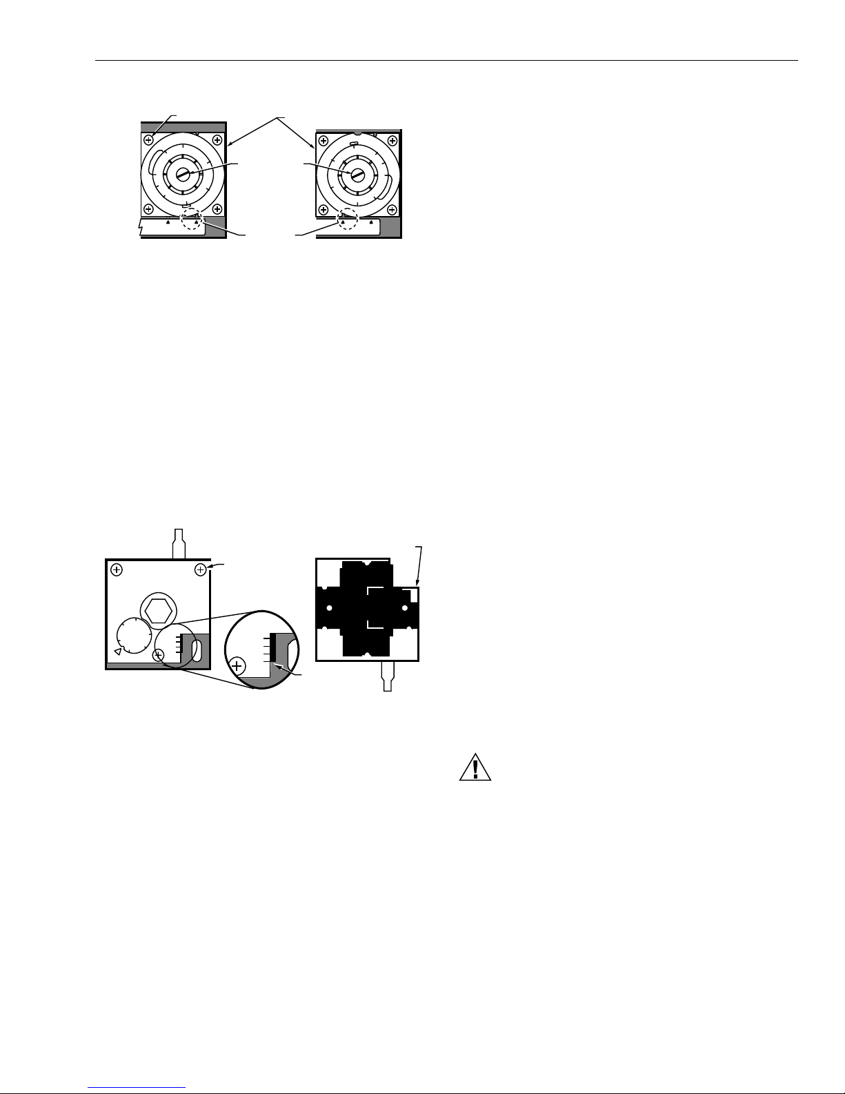
1.
Check the gasket tab position (Fig. 6, front view).
2.
Loosen the three switch block module screws and
remove the module.
3.
Remove the gasket and note the letters (B, B+, C, C+)
embossed on the module back.
4.
Rotate and/or flip the gasket until the gasket position
matches the functions desired (Fig. 6, back view).
RP920A,B,C,D MODULAR PNEUMATIC CONTROLLERS
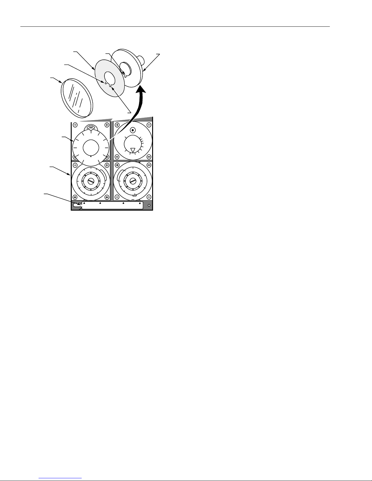
Adjustments:
1.
If using a scaleplate o ve r lay, insert the overlay betw ee n
the setpoint knob and the transparent overlay retainer.
Note positions of the key and non-coded scaleplate
overlay notch (Fig. 7).
2.
Adjust the setpoint (W
using the setpoint knob.
3.
If the control point deviates excessively from the
setpoint (W
consideration.
), calibrate, taking the throttling range into
1
), according to the job drawings,
1
REMOTE SETPOINT
Setpoint (W
primary sensor span from a remote 3 to 15 ps i (21 to 103 k Pa)
) is controlled from 0 to 100 percent of the
1
bleed-type signal.
Adjustments:
1.
Adjust the setpoint knob to 100 percent (Fig. 7) or to
the maximum remote setpoint limit to be applied.
2.
Install the 14003755-001 Barb Fitting and O-ring to
port 8 and connect to a bleed-type remote setpoint
device (e.g., SP970) and a remote setpoint gage.
NOTE: With the correct gasket position, only the
desired let ter shows.
5.
Install the gasket on the switch block module back.
6.
Reinstall the module, and tighten the three screws.
7.
If used, connect the integral action cut-off switching
components to ports 6 and 7.
GASKET SHOWN IN C POSTION. B, B+, AND C+ LEGENDS
CANNOT BE SEEN WITH GASKET IN THE C POSTION,
BUT ARE ILLUSTRATED HERE TO DISLPLAY LOCATION.
CAPTIVE SCREW (3)
Switch Block
+
B
+
C
B
C
B
B
+
GASKET TAB
IN C POSITION
C
C
+
BACK
C5105
60
FRONT
7 6 5
W
100
80
%
0
40
20
c
+
B
+
C
B
C
Fig. 6. Integral action cut-off and gage
function gasket position.
Setpoint (W1) Adjustment
The setpoint knob is embossed with a 0 to 100 percent scale
which correlates with the values in Table 3 (see Appendix).
Scaleplate overlays are included to directly match various
sensor ranges.
Three methods of controlling setpoint (W
LOCAL SETPOINT
Adjust setpoint (W
) directly on the controller.
1
) are available:
1
CONTROL POINT ADJUSTMENT (CPA)—AVAILABLE ON SPECIFIC
MODELS
Local (baseline) setpoint (W
and can be varied ±15 percent of the primary sensor span
) is adjusted on the controller
1
from a remote 3 to 15 psi (21 to 103 kPa) signal.
Adjustments:
1.
Pipe CPA to port 9.
2.
If used, select the proper scaleplate overlay.
3.
Note the position of key on the setpoint knob and the
non-coded scaleplate overlay notch (Fig. 7) for
controllers with U.S. A. labels. Controlle rs (RP920B,C,D)
with German labels must use “R” coded scaleplate
overlay notch when using a CPA device.
4.
Insert the scaleplate overlay between the setpoint knob
and the transparent overlay retainer.
5.
Adjust the setpoint (W
using the setpoint knob.
) according to the job drawings
1
Proportional Band (Xp) Adjustment
Adjust the proportional band (Xp), according to the job
drawings, using the proportional module proportional band
adjustment knob (see Fig. 2).
Control Loss Hazard.
Loosening knob screws can induce controller
leaks.
Use CCT819 and Authority S etting Ad justment Tool or
a narrow, stiff-blade putty knife to rotate adjustment
knobs (Xp and Ac).
Authority (Ac) Adjustment (RP920B and D only)
Adjust the authority (Ac), according to the job drawings, with the
compensation module authority adjustment knob (see Fig. 2).
3 95-7392EF
Page 4
RP920A,B,C,D MODULAR PNEUMATIC CONTROLLERS
SCALEPLATE OVERLAY
"R" CODED SCALEPLATE
OVERLAY NOTCH
OVERLAY
RETAINER
SETPOINT KNOB
Setpoint
Module
LABEL
C5106
SETPOINT
KNOB KEY
R
NON-CODED
SCALEPLATE
OVERLAY NOTCH
60
40
20
20
80
W
1
100
0
%
5
10
Xp (%)
45
40
30
DIR. REV. POS. NEG.
HONEYWELL
RP920
SETPOINT
KNOB
TR
0.5
1
Ac (%)
5
Min
20
15
10
7
5
4
3
1.5
2
250
300
200
150
50
100
Fig. 7. Setpoint (W1) Adjustment.
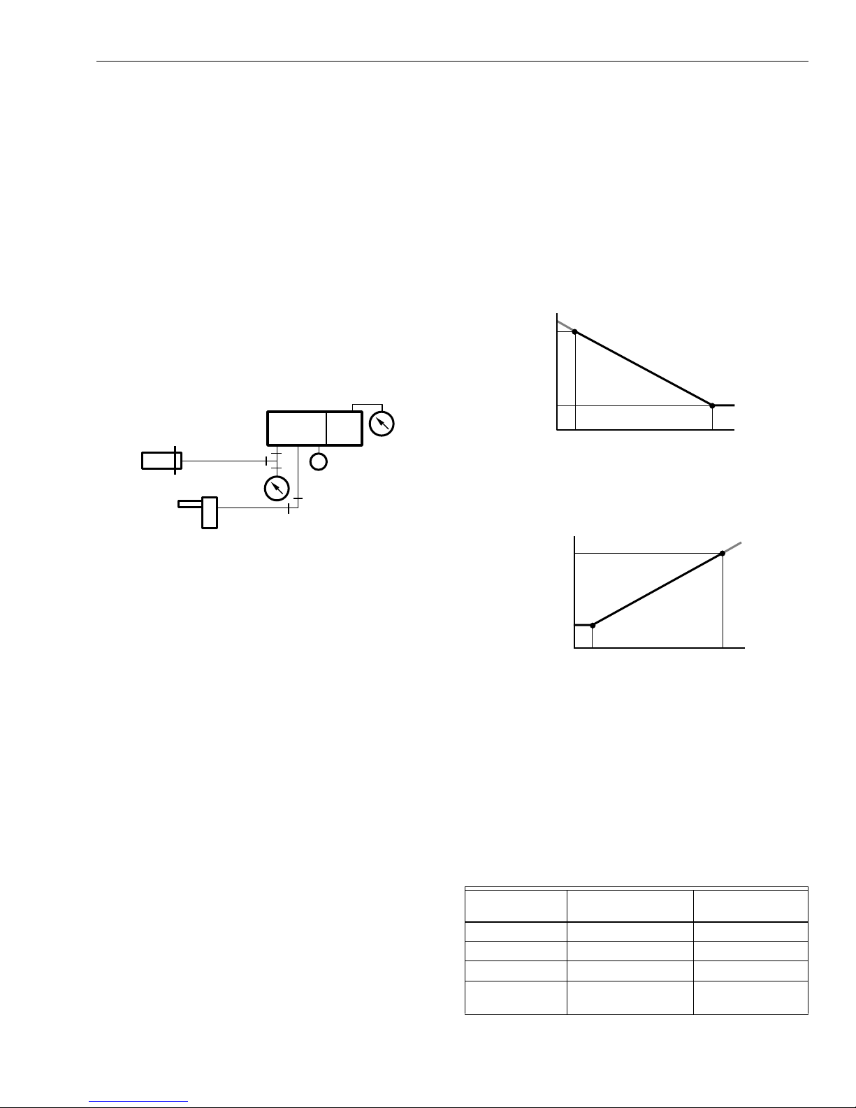
Compensation Startpoint (Wc) Adjustment
(RP920B and D only)
Adjust the compensation startpoint (Wc), according to the job
drawings (reset schedule), using the compensation startpoint
adjustment knob (see Fig. 2). For direct-acting sensors, the
knob setting is equal to the compensation value
corresponding to th e lowest value given for the pr imary senso r
(from the reset schedule). See Fig. 9 and 10. If the value
given is not a percentage, convert it to a percentage of the
compensation sensor range using Table 3 (see Appendix):
1.
Find the correct sensor range column.
2.
Find the desired temperature in the column.
3.
Read the equivalent pressure in the second column.
4.
Read the equivalent pe rcentage in the first co lumn.
Reset Time (Tr) Adjustment (RP920C and D only)
Adjust the reset time (Tr), according to the job drawing s, using
the reset time adjustment knob (see Fig. 2):
1.
Decrease setting until the system becomes unstable.
2.
Increase the setting slightly until the system becomes
stable.
Replacing Cover
1.
If a cover is used, snap the cover straight on the front.
2.
The cover can be secured further by tightening the selftapping screw in the cover lower right corner.
CALIBRATION
Sensors
Sensors are calibrated to the sy st em a nd req uire n o separate
calibration.
Systems
All RP920 Controllers a re f actory calibrat ed. It i s int end ed tha t
the controller be adjusted to the field-calculated values listed
on the job drawing. This controller startup approach will be
adequate for most systems. If it is determined that closer
calibration is required, use the following procedures:
NOTES:
— The controller allows all adjustments to be made
independently. For example, changing the
proportional band (X
calibration of the: setpoint (W
startpoi nt (W
— If a CPA device is used, apply 9 psi (62 kPa) to
), or authority (Ac) adjustment.
c
port 9.
— If a remote setpoint is used, block port 8.
RP920A System
1.
Install either:
a. a temporary receiver gage (matching the primary
sensor) or a 0 to 30 psi (0 to 207 kPa) gage in the
primary sensor gage port if one is not permanently
installed, or
b. a “tee” gage into the sensor line (port 3).
2.
Apply mainline pressure (MLP) to the system.
3.
Install a 0 to 3 0 psi (0 to 207 kPa) gag e in the branchli ne
pressure (BLP) test tap (moisten the needle before
inserting).
4.
If the sensor reading is greater than ±10 percent of the
expected setpoint, remove the se nsor tubing from por t 3
and apply a pressure equivalent (expected setpoint)
using a CCT816B Calibration Unit.
NOTE: For the most accurate calibration, the actual
measured variable at the sensor must be
±10 percent of the expec ted se tpo int.
5.
With the sensor at or near the desired control point,
adjust the setpoint knob until the BLP equals the
controlled device throttling range midpoint, e.g., 8 psi
(55 kPa) for a 3 to 13 psi (21 to 90 kPa) range device.
6.
If the setpoint (W
match, remove the setpoint knob and replace it so the
) and primary sensor gage do not
1
setpoint matches the primary sensor gage reading.
7.
Ensure W
8.
Calibration is complete.
is at the desired setpoint.
1
RP920B Systems
1.
Install in port 5 either a receiver gage that matches the
compensation sensor, or a 0 to 30 psi (0 to 207 kPa)
gage (see Fig. 8).
) setting does not affect the
p
), compensation
1
95-7392EF 4
NOTE: If the controller is setup for a compensation
gage in the right gage p ort, plug port 5 and use
the existing gage.
Page 5
RP920A,B,C,D MODULAR PNEUMATIC CONTROLLERS
PRIMARY SENSOR
FULL
COMP
SETPOINT
(W1 )
COMPENSATION
STARTPOINT (Wc )
COMPENSATION SENSOR
C5111
2.
Install a 0 to 30 psi (0 to 207 kPa) gage in BLP test tap
or in BLP gage port if one is not permanently installed.
3.
Apply MLP to the system.
4.
Adjust the authority knob to minimum.
5.
Adjust the compensation startpoint knob until the
receiver gage (port 5) reads the pressure equivalent of
the compensation startpoint (W
6.
If the compensation startpoint (W
startpoint do not match, rem ov e the k no b and re pla ce it
) (Fig. 9 or 10).
c
) and desired
c
so they do match.
7.
The compensation startpoint (W
) is now calibrated.
c
NOTE: The response of the receiver gage may be
slow (up to one minute). The controller is not
defective under these conditions.
8.
Set up the CCT816B Calibration Unit (Fig. 11) to
connect to port 3 (primary sensor).
NOTE: Sensors are not connected.
THE GAGE RANGE MUST
MATCH THE RANGE OF THE
SENSOR FEEDING PORT 5
PRIMARY
SENSOR
4 8 9 7 5
2 3 1 6
M
C5109
17.
Remove the CCT816B Calibration Unit and pipe
sensors.
RP920C and D Systems
1.
Remove the integral module screw (Fig. 13) and install
the 14003755-001 Barb Fitting and O-ring in its place.
2.
Apply 8 psi (55 kPa) to the integral module.
3.
Calibrate the RP920:
a. RP920C: follow the procedure for the RP920A.
b. RP920D: follow the procedure for the RP920B
except that the calibration value of the BLP for
4.
Fig. 9. Negative compensation calibration reset sc hedule.
Steps 10 and 15 should both be 8 psi (55 kPa).
When calibration is complete, remove the barb fitting
from the integral module and replace the screw.
FULL
COMP
PRIMARY SENSOR
SETPOINT
(W 1)
COMPENSATION
STARTPOINT (Wc )
C5110
COMPENSATION SENSOR
Fig. 8. Piping for RP920B compensation
startpoint (W
9.
Apply a pressu re equ ivale nt of the p rimary sen sor valu e
c
corresponding to the compensation start (
the reset schedule (Fig. 9 or 10).
10.
Adjust the setpoint knob until the BLP equals the
expected pressur e of the cont rolled device at
conditions.
11.
If needed, remove the setpoint knob and replace it
so the setpoint matches the primary sensor value at
comp start
12.
The setpoint (W
13.
Set up the CCT816B Calibration Unit (Fig. 12) to
.
) is now calibrated.
1
connect to port 3 (primary sensor) and port 5
(compensation sensor).
14.
Apply sensor input pressures equivalent to the full
compensation on the building schedule.
15.
Adjust the authority (A
expected pressure of the controlled device at full
) knob until the BLP equals the
c
compensation conditions.
16.
Calibration is complete.
IMPORTANT
Changing compensation startpoi nt (W
(W1) affects only the one corresponding value of the
reset schedule, while changing authority (A
only the slope of the reset schedule.
NOTE: See the Compensation Startpoint (W
Adjustment section for more information.
) setting.
comp start
comp start
) or setpoint
c
) affects
c
)
c
) on
Fig. 10. Positive co m pen sa ti on c al ibr a ti on r e se t sc he du le .
RP920B Calibration Example
Assume the following conditions:
— A 10°F (5.6K) throttling range.
— Using a 2.5 to 6.5 psi (17 to 45 kPa) operator with a
normally open (N.O.) valve where conditions are: 6.5 psi
(45 kPa) with no load and 2.5 psi (17 kPa) with full load.
— See Fig. 14 for the schedule graph.
— See Table 2 for the reset schedule.
Table 2. Reset Schedule.
Compensation
Range
Start 120°F (49°C) (40%) 60°F (16°C) (50%)
Full 160°F (71°C) (60%) 0°F (-18°C) (20%)
Operating Span 40°F (22K) 60°F (33K)
Sensor Range 40 to 240°F
5 95-7392EF
Primary Sensor
(Discharge)
(4 to 11 6°C)
Compensation
Sensor (OA)
-40 to 160°F
(-40 to 71°C)
Page 6

RP920A,B,C,D MODULAR PNEUMATIC CONTROLLERS
Printed in U.S.A. on recycled
paper containing at least 10%
post-consumer paper fibers.
CCT816B
CALIBRATION UNIT
3
NO
CONNECTION
PRIMARY
SENSOR
C5112
4 8 9 7 5
2 3 1 6
M
NO
CONNECTION
PRIMARY SENSOR
RESTRICTION
SWITCH
BLOCKED
M
(BLOCKED RESTRICTION
ALTERNATE OK)
Fig. 11. RP920B setpoint (W1) CCT816B
Calibration Unit piping.
Initial Settings:
(W
Setpoint
)
= 120°F (49°C) = 40% = 7.8 psi (53.8 kPa).
1
For Calibration Step 5:
Compensation sensor at start = Compensation startpoint
W
= 60°F (15°C) = 50% = 9 psi (62 kPa)
c
For Calibration Step 9:
Primary sensor at start = 120° F (49°C) or 7.8 psi (53 .8 kPa)
For Calibration Step 10:
Desired BLP = 6.5 psi (45 kPa)
For Calibration Step 15:
Primary sensor at full compensation =
160°F (71°C) = 10.2 psi (70 kPa)
Compensation sensor at full compensation =
0°F (-18°C) = 5.4 psi (37.2 kPa)
Expected BLP = 2.5 psi (17 kPa)
(W )
COMPENSATION
SENSOR
M
489 7 5
231 6
M
NO
CONNECTION
PRIMARY
SENSOR
C5113
PRIMARY SENSOR
RESTRICTION
SWITCH
BLOCKED
M
Fig. 12. RP920B authority (A
c
Calibration Unit piping.
TR
0.5
1
1.5
Min
20
15
10
7
5
4
3
2
INSTALL 14003755-001
BARB FITTING AND APPLY
8.0 PSI (55 kPa)
INTEGRAL
MODULE
CCT816B
CALIBRATION UNIT
3
NO
CONNECTION
(BLOCKED RESTRICTION
ALTERNATE OK)
) CCT816B
c
C5114
M
Fig. 13. Integral module piping.
Home and Building Control Home and Building Control Honeywell Asia Pacific Inc. Honeywell Europe S.A. Honeywell Latin American
Honeywell Honeywell Limited-Honeywell Limitée Room 3213-3225 3 Avenue du Bourget Region
1985 Douglas Drive North 35 Dynamic Drive Sun Hung Kai Centre 1140 Brussels 480 Sawgrass Corporate Parkway
Golden Valley, MN 55422 Scarborough, Ontario No. 30 Harbour Road Belgium Suite 200
M1V 4Z9 Wanchai Sunrise FL 33325
95-7392EF B.B. 8-00
Hong Kong
160F
FULL
(71C)
COMP
120F
SETPOINT
PRIMARY SENSOR
(48C)
(W )
1
0F
(–18C)
COMPENSATION
STARTPOINT (W )
COMPENSATION SENSOR
2.5 PSI
(17.5 kPa)
EXPECTED
BLP
6.5 PSI
(45.5 kPa)
c
C5115
Fig. 14. Calibration example reset schedule.
www.honeywell.com
Page 7

Régulateurs pneumatiques modulaires
75 (3) DÉGAGEMENT MINIMAL
102
(4)
86 (3-3/8)
7
(9/32)
RP920A: 36 (1-1/2)
RP920B-D: 83 (3-1/4)
148
(5-7/8)
3 (1/8)
ESPACEMENT
MINIMAL
ENTRE LES
MODULES
RP920A: 48 (1-7/8)
RP920B-D: 96 (3-13/16)
MF17581
INSTALLATION
Réglage à effectuer avant l’installation
1.
S’il faut une connexion aux orifices 4,6, 7 ou 8 (Fig. 2),
retirer la vis autota raudeuse d e l’orific e 8 et util iser la vi s
pour tarauder l’orifice adéquat.
2.
Installer le raccord à crans 14003755-001 et le joint
torique sur l’orifice adéquat et serrer à la main.
3.
Replacer la vis dans l’orifice 8 s’il n’est pas utilisé.
4.
Si on emploie un restricteur à distance avec le capteur
primaire, bloquer l’orifice interne d’alimentation en air
(il peut être réglé après l’installation du manomètre,
mais il est plus facile de le régler avant) :
a. Dévisser la vis d’un tour (Fig. 3) et faire tourner la
plaque de commutation de 90 degrés dans le sens
antihoraire pour mettre l’alim en tati on du cap teu r en
position bloquée.
b. Resserrer la vis et vérifier s’il y a des fuites. En cas
de fuite, replacer la plaque de commutation.
RP920A,B,C,D
NOTICE D’INSTALLATION
REMARQUES :
— La vis de la plaque de commutation doit être bien
— Le capteur de compensation de l’orifice 5 exige
Installation de l’appareil
1.
À l’aide du régulateur comme gabarit ou après avoir
consulté l’encombrement à la Fig. 1, marquer et percer
deux ouvertures de montage pouvant recevoir des
attaches n
2.
Installer le régulateur au moyen de deux attaches n
(non fournies).
serrée pour éviter une fausse défaillance du
capteur.
l’emploi d’un restricte ur extern e de la c analisati on
principale d’alimentati on en air.
o
8.
o
8
Fig. 1. Encombrement du RP920 en mm (po).
Raccordements
1.
Pousser la canalisation sur le raccord à crans
conformément aux plans de l’installation. Voir la Fig. 2
pour connaître l’emplac em en t de s orifi ce s.
2.
Installer le manomètre ou le bouchon :
a. Si le manomètre n’est pas utilisé, resserrer à la
main le bouchon de la prise de manomètre. Si un
manomètre est utilisé, retirer le bouchon et, à la
main, insérer le manomèt re dans l’ orifice rése rvé au
manomètre en lui faisant faire trois tours.
b. Si le manomètre est mal orienté, le faire tourner
dans le sens antihoraire jusqu’à ce que le cadran
soit correct.
REMARQUE : Un joint de caoutchouc souple installé
en usine permet de faire tourner le
manomètre (pour le mettre dans la
bonne position) sans provoquer de
fuites.
® Marque déposée aux É.-U.
Copyright © 2000 Honeywell Tous droits réservés
95- 7392EF
Page 8

RÉGULATEURS PNEUMATIQUES MODULAIRES RP920A,B,C,D
PRISE DE
MANOMÈTRE
ORIFICE DU
MANOMÈTRE
DU CAPTEUR
PRIMAIRE
Bloc de
raccordement
PRISE D'ESSAI
PRESSION
SECONDAIRE
Module du
point de
consigne
Module de
régulation
proportionnelle
RP920A
4 8 9
2 3 1
60
40
20
W
1
0
%
5
10
20
40
30
DIR.
REV.
RP920A
1 - CANALISATION
PRINCIPALE
2 - CANALISATION
SECONDAIRE
132
3 - CAPTEUR
PRIMAIRE
4 - ÉVENT
8 - POINT DE
CONSIGNE
FERMÉ/À DISTANCE
9 - RÉGLAGE DU
POINT DE
CONTRÔLE (RPC)
80
100
Xp (%)
45
ORIFICE DU MANOMÈTRE
DU CAPTEUR
PRIMAIRE
Bloc de
raccordement
PRISE D'ESSAI
PRESSION
SECONDAIRE
Module du
point de
consigne
BOUTON DE RÉGLAGE
DE LA
BANDE
PROPORTIONELLE
Module de
régulation
proportionnelle
RP920B,C,D
4 8 9
32
2 3 1
60
40
20
W
1
100
0
%
5
10
20
40
30
DIR. REV.
1
80
Xp (%)
45
RP920D
7
6
PRISES DE
MANOMÈTRE
7 6 5
100
80
Wc
%
0
60
B
+
C
+
20
40
B
C
TR
Min
0.5
20
4
1
3
1.5
2
250
300
200
Ac (%)
5
150
50
100
NEG.
POS.
5
15
10
7
5
1 - CANALISATION PRINCIPALE
2 - CANALISATION SECONDAIRE
3 - CAPTEUR PRIMAIRE
4 - ÉVENT
5 - CAPTEUR DE
COMPENSATION
6 - ÉVENT
7 - ÉVENT
8 - POINT DE CONSIGNE
FERMÉ/À DISTANCE
9 - RPC
CAPTEUR DE COMPENSATION OU
ORIFICE DU MANOMÈTRE DE
PRESSION SECONDAIRE
BOUTON DE RÉGLAGE DU POINT
DE DÉPART DE LA COMPENSATION
Bloc de
commutation
Module de
régulation
intégrale
Module de
compensation
VIS DU BOUTON DU MODULE
(NE PAS DESSERRER)
1
2
Fig. 2. Emplacement des modules et des orifices.
Bloc de
connexion
2 3 1
ALIMENTATION
DU CAPTEUR
OUVERTE
PLAQUE DE COMMUTATION
INDICATEUR DE POSITION
POSITION OUVERTE
POSITION BLOQUÉE
ALIMENTATION
DU CAPTEUR BLOQUÉE
(RESTRICTEUR EXTERNE)
VIS
PLAQUE
DE COMMUTATION
Fig. 3. Alimentation en air du capteur primaire.
RP920C, D SEULEMENT.
1
Ajustements et modifications après montage
CF5102
Modification de l’action du régulateur
RP920B, D SEULEMENT.
2
VIS IMPERDABLES (4)
5
10
Xp (%)
20
45
40
30
DIR. REV. DIR. REV.
NE PAS
RÉGLER
LA VIS
NOTER
L’EMPLACEMENT
DE L’ENCOCHE
ÉTIQUETTE
DU RÉGULATEUR
ACTION DIRECTE
Module de régulation
proportionnelle
40
45
30
Xp (%)
10
5
ACTION INVERSE
Fig. 4. Modification de l’action du contrôleur.
1.
Dévisser les quatre vis (Fi g. 4 ) du mo dul e de r égulation
proportionnelle.
2.
Retirer le module.
3.
Faire tourner le module et son joint d’étanchéité de
180 degrés, puis le réinstaller. S’assurer que l’encoche
du module est vis-à-vis l’indication adéquate de
l’étiquette du régulateur (base).
4.
Resserrer les quatre vis.
5.
Étalonner de nouveau, au besoin.
MF17584
20
CF5103
95-7392EF 2
Page 9

Passage de la compensation négative (hiver) à la
JOINT D’ÉTANCHÉITÉ EN POSITION C. NORMALEMENT,
LES LETTRES B, B+ ET C+ N’APPARAISSENT PAS
LORSQUE LE JOINT EST EN POSITION C ; ELLES SONT
ILLUSTRÉES POUR INDIQUER LEUR EMPLACEMENT.
CF5105
LANGUETTE
DU JOINT
D’ÉTANCHÉITÉ
DEVANT
ARRIÈRE
VIS IMPERDABLES (3)
Bloc de
commutation
7 6 5
40
20
0
60
80
100
%
W
c
C
B
C
+
+
B
B
C
B
C
+
+
B
B
+
C
+
C
EN POSITION C
compensation positive (été) (RP920B et D seulement)
1.
Desserrer les quatre vis (Fig. 5) du module de
compensation.
2.
Retirer le module.
3.
Faire tourner le module et son joint d’étanchéité de
180 degrés, puis le réinstaller. S’assurer que l’encoche
du module est vis-à-vis l’indication adéquate de
l’étiquette du régulateur (base).
4.
Resserrer les quatre vis.
5.
Étalonner de nouveau, au besoin
.
Ajustement de la fonction manomètre et blocage de
l’action intégrale (RP920C et D)
La position du joint d’étanchéité situé sous le module du bloc
de commutation (Fig. 2) détermine la fonction du manomètre
installé sur place sur le bloc de commutation. Elle détermine
également si l’action intégrale est bloquée ou non. Voir le
Tableau 1 pour connaître les réglages de l’usine et ceux qu’il
est possible de faire sur place.
RÉGULATEURS PNEUMATIQUES MODULAIRES RP920A,B,C,D
7.
Raccorder les composants de commutation du blocage
de l’action intégrale aux orifices 6 et 7, selon le cas.
Réglage du point de consigne (W1)
Le bouton de réglage du point de consigne (W1) est marqué
en relief d’une échelle allant de 0 à 100 %; cette échelle
correspond aux valeurs énumérées au Tableau 3 (voir
Annexe). Plusieurs caches acco mpagnent le r égulateur pour
que le bouton de réglage puisse correspondre à diverses
plages de service du capteur.
Il existe trois méthode s de r églage du po int de co nsig ne (W
1
):
Tableau 1. Position du joint d’étanchéité
du bloc de commutation
Modèle Réglage de l’usine
a
Options
RP920B B C
RP920C B B+
RP920D B C, C+, B+
a
Expédié de l’usine dans cette position.
B = Manomètre dans la canalisation secondaire.
C = Manomètre du capteur de compensation.
+ = Action intégrale bloquée.
VIS IMPERDABLES (4)
250
300
Ac (%)
COMP. NÉGATIVE
(RÉGLAGE DE L’USINE)
200
5
50
POS.
150
100
NEG.
L’EMPLACEMENT DE
L’ENCOCHE
Module de compensation
NE PAS
AJUSTER
LES VIS
NOTER
100
150
200
250
POS.NEG.
COMP. POSITIVE
Fig. 5. Passage de la compensation négative
à la compensation positive.
50
300
CF5104
5
Ac (%)
Fig. 6. Position du joint d’étanchéité selon la fonction du
manomètre et le blocage de l’action intégrale.
POINT DE CONSIGNE LOCAL
Le bouton de réglage du point de consigne (W
directement au régulateur.
) est réglé
1
Ajustements :
1.
Si on utilise un cache, insérer ce cache entre le bouton
de réglage du point de consigne et la rondelle de
retenue transparente. Noter la position de la clé et de
l’encoche non codée du cache (Fig. 7).
2.
Ajuster le point de consigne (W
utilisant le bouton de réglage du point de consigne.
3.
Étalonner seulement si le poi nt de contr ôle s’écart e trop
du point de consigne (W
bande proportionnelle.
1
) selon les plans en
1
) en tenant compte de la
POINT DE CONSIGNE À DISTANCE
Point de consigne (W1) commandé de 0 à 100 % de la
gamme du capteur primaire à partir d’un signal de type purge
de 3 à 15 psi (21 à 103 kPa).
1.
Vérifier la position de la languette du joint d’étanchéité
(Fig. 6, vue du devant).
2.
Dévisser les trois vis du bloc de commutation et retirer
le module.
3.
Retirer le joint d’étanchéité et remarquer les lettres (B,
B+, C, C+) en relief sur le revers du module.
4.
Faire tourner ou basculer le joint d ’étanchéité jusqu’à ce
que sa position corresponde à la fonction souhaitée
(Fig. 6, arrière).
REMARQUE : Lorsque la position est la bonne , seule la
5.
Installer le joint d’étanchéité au dos du module du bloc
de commutation.
6.
Réinstaller le module, puis resserrer les trois vis.
lettre voulue est visible.
Ajustements :
1.
Ajuster le bouton du point de consigne (W
(Fig. 7) ou à la valeur de consigne maximale souhaitée.
2.
Installer le raccord à crans 14003755-001 et le joint
) à 100 %
1
torique sur l’orifice 8 et raccorder à un appareil à point
de consigne de ty pe purge (par exem ple à un SP970) et
à un manomètre de point de consigne à distance.
RÉGLAGE DU POINT DE CONTRÔLE – OFFERT AVEC CERTAINS
MODÈLES SEULEMENT
Le point de consigne (W
régulateur et peut varier de ± 15 % par ra pport à l’intervalle du
) local (de référence) est ajusté au
1
capteur primaire à partir d’un signal à distance de 3 à 15 psi
(21 à 103 kPa).
3 95-7392EF
Page 10

RÉGULATEURS PNEUMATIQUES MODULAIRES RP920A,B,C,D
Ajustements :
1.
Installer une canalisation entre le dispositif de réglage
du point de contrôle et l’orifice 9.
2.
Sélectionner le cache adéquat, selon le cas.
3.
Dans le cas de régulateurs port ant une étiquette
américaine, noter la position de la clé et de l’encoche
non codée du cache (Fig. 7). D ans le cas de régulateurs
portant une étiquette allemande (RP920B,C,D), utiliser
le cache portant une encoche identifiée par la lettre R
lorsqu’un appareil avec réglage du point de co ntrôle es t
employé.
4.
Insérer le cache entre le bouton de réglage du point de
consigne et la rondelle de retenue transparente.
5.
Ajuster le point de consigne (W
utilisant le bouton de réglage du point de consigne.
CLÉ DU BOUTON
DE RÉGLAGE
CACHE
CACHE AVEC ENCOCHE
CODÉE "R"
RONDELLE
DE RETENUE
TRANSPARENTE
BOUTON DE
RÉGLAGE DU POINT
DE CONSIGNE
Module du
point de
consigne
ÉTIQUETTE
CF5106
DU POINT DE
CONSIGNE
60
40
20
W
1
0
%
5
10
20
30
DIR. REV. POS. NEG.
HONEYWELL
) selon les plans en
1
BOUTON DE RÉGLAGE
R
CACHE
AVEC ENCOCHE
NON CODÉE
TR
0.5
80
RP920
1
Ac (%)
5
40
100
Xp (%)
45
DU POINT DE
CONSIGNE
1.5
2
250
300
50
100
Fig. 7. Ajustement du point de consigne (W
Réglage de l’autorité (Ac) (RP920B et D seulement)
Régler l’autorité (Ac) selon les plans en utilisant le bouton de
réglage de l’autorité (A
.
(Fig. 2)
) situé sur le module de compen sation
c
Réglage du point de départ de la compensation (Wc)
(RP920B et D seulement)
Régler le point de départ de la compensation (Wc) selon les
plans (tableau de compensation) à l’aide du bouton de réglage
du point de départ de la compensation (W
cas de capteurs à action directe, le réglage du bouton est égal
) (Fig. 2). Dans le
c
à la valeur de compensation correspondant à la valeur la plus
basse indiquée pour le capteur primaire (en fonction du tableau
de compensation). Voir les Fig. 9 et 10. Si la valeur indiquée
n’est pas exprimée en pourcentage, convertir cette valeur en
pourcentage de la gamme du capteur de compensation ou
consulter le T ableau 2. V oici comment utiliser le Tableau 3 (voir
Annexe) :
1.
Trouver d’abord la colonne correspondant à la gamme
du capteur.
2.
Trouver ensuite la température souhaitée dans le
tableau.
3.
Relever la pression équivalente dans la deuxième
colonne.
4.
Relever le pourcentage équivalent dans la première
colonne.
Ajustement du délai de compensation (Tr)
(RP920C et D seulement)
Min
20
15
10
7
5
4
3
200
150
).
1
Régler le délai de comp ens ation (Tr) en fonction des p lan s e n
utilisant le bouton de réglage du délai de compensation (T
(Fig. 2) :
1.
Abaisser le réglage jusq u’à ce que le syst ème d ev ienne
)
r
instable.
2.
Augmenter le réglage légèrement jusqu’à ce que le
système redevienne stable.
Couvercle
1.
Si l’on se sert du couvercle, rabaisser le couvercle en
droite ligne à partir du devant.
2.
Le couvercle peut être fixé plus solidement : il suffit de
resserrer la vis autotaraudeuse située dans le coin
inférieur droit du couvercle.
Réglage de la bande proportionnelle (Xp)
Ajuster la bande proportio nnell e (Xp) en fonction des plan s en
utilisant le bouton de rég lag e d e la bande proportio nne lle (X
situé sur le module de régulation propor tionnelle (Fig. 2).
MISE EN GARDE
Risque de perte du signal.
Le fait de serrer la vis du bouton peut provoquer
une fuite du régulateur.
Utiliser l’outil CCT819 servant à régler l’autorité, ou
encore un co uteau à mastic mince et rigide pour faire
tourner le bouton (X
95-7392EF 4
et Ac).
p
ÉTALONNAGE
)
p
Capteurs
Les capteurs n’ont pas be soin d’être étalonnés puisqu’ils sont
étalonnés en fonction du système.
Systèmes
Tous les régulateurs RP920 sont étalonnés en usine. Il est
prévu que le régulateur soit ajusté selon les valeurs de
l’installation indiqu ée s sur l es pla ns . Cette façon de mettre en
service le régulateur convi ent en prin cipe à la plupart des
systèmes. S’il est déterminé qu’un étalonnage plus précis est
nécessaire, s uivre les étapes ci-dessous :
Page 11

RÉGULATEURS PNEUMATIQUES MODULAIRES RP920A,B,C,D
M
CAPTEUR
PRIMAIRE
4 8 9 7 5
2 3 1 6
LA GAMME DU MANOMÈTRE DOIT CORRESPONDRE
À CELLE DU CAPTEUR QUI ALIMENTE L’ORIFICE 5.
CF5109
REMARQUE :
— Le régulate ur est conçu de façon que tous les
réglages puiss ent être effectués indépendamment
les uns des autres . Par exemple, la modification
de la bande proportionnelle ( Xp) n’a pas d’effet
sur l’étalonnage du point de consigne (W1), le
point de départ de la compensation (W c) ou le
réglage de l’autorité (Ac).
— Si un dispositif de réglage du po int de contrôle est
employé, appliquer une pression de 9 psi
(62 kPa) à l’orifice 9.
— Si un point de consigne à distance est utilisé,
bloquer l’orifice 8.
Système RP920A
1.
Installer :
a. soit un manomètre récepteur temporaire
(correspondant au capteur primaire) ou un
manomètre de 0 à 30 psi (0 à 207 kPa) da ns l’orifice
du manomètre du capteur primaire si un tel
manomètre n’est pas déjà installé en permanence,
ou encore.
b. installer un manomètre en T dans la canalisation du
2.
3.
4.
capteur (orifice 3).
Appliquer la pression de la canalisation principale au
système.
Installer un manomètre de 0 à 30 psi (0 à 207 kP a) dans
la prise d’essai de la pression de la canalisation
secondaire (hum idifier la pointe du manom ètre ava nt de
l’insérer).
Si le relevé du capteur est sup érieur de ± 10 % au point
de consigne prévu, retirer la canalisation du capteur de
l’orifice 3 et appliquer une pression équivalente (point
de consigne prévu) au moyen de l’instrument
d’étalonnage CCT816B.
2.
Installer un manomètre de 0 à 30 psi (0 à 207 kPa) dans
la prise d’essai de la canalisation secondaire ou dans
l’orifice de m anomètre de la canalisation second aire s’il
n’y a pas déjà un manomètre inst allé en permanence.
3.
Appliquer la pression de la canalisation principale au
système.
4.
Ajuster le bouton de réglage de l’autorité (A
minimum.
5.
Ajuster le bouton de réglage du point de départ de la
) au
c
compensation jusqu ’à ce que le manomètre récepteur
(orifice 5) indique une pression équivalente au point de
départ de la co mpensation (W
6.
Si le bouton du point de départ (W
départ ne correspondent pas, retirer le bouton et le
), (Fig. 9 ou 10).
c
) et le point de
c
replacer de façon qu’il corresponde au point de départ.
7.
Le point de départ de la compensation (W
maintenant étalonné.
) est
c
REMARQUE : Il se peut que le manom ètre récepteur
soit lent à réagir (jusqu’à une minute).
Le régulateur n’es t pas po ur au tan t
défectueux.
8.
Fixer l’unité d’étalonnage CCT816B (Fig. 11) à l’orifice 3
(capteur primaire).
REMARQUE : Les capteurs ne sont pas raccordés.
REMARQUE : Pour un étalonnage plus précis, la
5.
Si le capteur est au point de contrôle prévu ou à une
valeur satisfaisante, ajuster le bouton de réglage du
point de consigne (W
canalisation secondaire soit égale au centre de la
bande proportionnelle de l’appareil à régler, par
exemple, 8 psi (55 kPa) pour un appareil d ont la gamme
est de 3 à 13 psi (21 à 90 kPa).
6.
Si le point de c onsigne (W
primaire ne correspondent pas, retirer le bouton de
réglage du point de consigne (W
façon que le point de consigne corresponde au relevé
du manomètre du capteur primaire.
7.
S’assurer que le point de consigne (W
souhaitée.
8.
L’ét alo nna ge es t ter miné.
Système RP920B
1.
Installer un manomètre récepteur correspondant au
capteur de compensation ou un manomètre de 0 à 30
psi (0 à 207 kPa) dans l’orifice 5, comme l’illustre la
Fig. 8.
REMARQUE : Si le régulateur comporte un manomètre
variable réelle mesurée au capteur doit
être à ± 10 % du point de consigne
prévu.
) jusqu’à ce que la pression de la
1
) et le manomètre du capteur
1
) et le replacer de
1
) à la valeur
1
de compensation dans l’orifice de
manomètre adéquat, bloquer l’orifice 5
et utiliser le manomètre existant.
Fig. 8. Raccordement des canalisations pour le réglage
du point de départ de la compensation (W
9.
Appliquer une pression équivalente à la valeur du
) du RP920B.
c
capteur primaire qui corr espond au poi nt de départ de l a
compensation (
comp start
) figurant dans le tableau de
compensation (Fig. 9 ou 10).
10.
Ajuster le bouton du poi nt de cons igne jusq u’à ce q ue la
pression de la canalisation secondaire soit égale à la
pression prévue de l’appareil à régler lorsque les
conditions de point de départ de la compensation sont
atteintes.
11.
Au besoin, retirer le bouton du point de consigne et le
replacer de façon qu’il correspon de à la valeur du
capteur primaire au po in t de départ de la compensa tion.
12.
Le point de consigne (W
13.
Fixer l’unité d’étalonnage CCT816 B (Fig. 12) à l’orifice 3
) est maintenant étalonné.
1
(capteur primaire) et à l’orifice 5 (capteur de
compensation).
14.
Appliquer des pressions d’entrée au capteur
équivalentes à la pleine compensation selon le tableau
de compensation du bâtiment.
5 95-7392EF
Page 12

RÉGULATEURS PNEUMATIQUES MODULAIRES RP920A,B,C,D
15.
Ajuster le bouton de réglag e de l’autorité (A
que la pression de la canalisation secondaire
) jusqu’à ce
c
corresponde à la pression prévue de l’appareil à régler
aux conditions de pleine compensation.
16.
L’ét alo nna ge es t main ten ant term in é.
PLEINE
COMPENSATION
IMPORTANT
La modification du point de départ de la compensati on
) ou du point de consi gne (W1) n’a d’effet que sur
(W
c
la valeur correspondan te du tableau de compensation,
tandis que la modifi ca tion de l’autorité (A
que sur la pente du tab lea u de com pe nsa tion .
REMARQUE : Voir la section sur l’ajustement du point
de départ de la compensation (W
obtenir pl us de détails.
17.
Retirer l’unité d’étalonnage CCT816B et raccorder les
capteurs aux canalisations.
Systèmes RP920C et D
1.
Retirer la vis du mo dule d e r égulat ion in tégrale (Fig. 13)
et installer le raccord à crans 14003755-001 et le joint
torique à la place.
2.
Appliquer une pression de 8 psi (55 kPa) au module de
régulation intégrale.
3.
Étalonner le RP920 comme suit :
a. RP920C : suivre les mêmes directives que pour le
RP920A.
b. RP920D : suivre les mêmes directives que pour le
RP920B; les valeur s d’étalonn age de la pres sion de
la canalisation secondaire aux étapes 10 et 15
devraient toutefois être de 8 psi dans (55 kPa) dans
4.
les deux cas.
Une fois l’étalonnage terminé, retirer le raccord à crans
du module de régulation intégrale et remettre la vis en
place.
PLEINE
COMPENSATION
) n’a d’effet
c
) pour
c
CAPTEUR
PRIMAIRE
POINT DE
CONSIGNE
(W1 )
POINT DE DÉPART DE
LA COMPENSATION (Wc )
DÉPART
COMPENSATION
CAPTEUR
DE COMPENSATION
C5111
Fig. 10. Tableau de compensation pour l’étalonnage
de la compensation positive.
4 8 9 7 5
2 3 1 6
UNITÉ D’ÉTALONNAGE CCT816B
M
PAS DE RACCORDEMENT
CAPTEUR
PRIMAIRE
INTERRUPTEUR DE
LA RESTRICTION DU
CAPTEUR
PRIMAIRE
BLOQUÉ
M
3
CAPTEUR
PRIMAIRE
POINT DE
CONSIGNE
(W1)
CAPTEUR DE
COMPENSATION
POINT DE DÉPART
DE LA COMPENSATION
(Wc )
Fig. 9. Tableau de compensation pour l’étalonnage
de la compensation négative.
95-7392EF 6
DÉPART
COMPENSATION
CF5110
PAS DE RACCORDEMENT
(AUTRE MÉTHODE DE BLOCAGE
DE LA RESTRICTION ACCEPTABLE)
Fig. 11. Raccordement des canalisations pour
l’unité CCT816B servant à l’étalonnage
du point de consigne (W
) du RP920B.
1
Exemple d’étalonnage du RP920B
Supposons les condition s sui va nte s :
1.
Bande proportionnelle de 10 °F (5,6 K).
2.
Supposons également un opérateur de 2,5 à 6,5 psi
(17 à 45 kPa) avec vanne n.o. où 6,5 psi (45 kPa)
équivaut à une charge nulle et 2,5 psi (17 kPa) à une
pleine charge.
3.
Voir la Fig. 14 pour obtenir le graphique du tableau de
compensation.
4.
Voir le Tableau 2 pour obtenir le tableau de
compensation.
CF5112
Page 13

RÉGULATEURS PNEUMATIQUES MODULAIRES RP920A,B,C,D
Capteur primaire au départ = 120 °F (49 °C) ou 7,8 psi (53,8 kPa)
Pression désirée à la canalisation secondaire = 6,5 psi (45 k Pa)
Capteur de compensation à la pleine compensation =
0 °F (-18 °C) = 5,4 psi (37,2 kPa)
Pression désirée à la canalisation secondaire = 2,5 psi (17 k Pa)
1
1.5
2
3
4
5
7
10
15
20
Min
0.5
TR
INSTALLER UN RACCORD À CRANS
14003755-001 ET APPLIQUER UNE
PRESSION DE 8 PSI (55 kPa)
MODULE DE
RÉGULATION
INTÉGRALE
CF5114
CAPTEUR PRIMAIRE
2.5 PSI
(71 °C)
160 °F
(18 kPa)
PLEINE
COMPENSATION
POINT DE
CONSIGNE
(W )
1
PRESSION PRÉVUE
À LA CANALISATION
SECONDAIRE
6.5 PSI
(49 °C)
120 °F
(45 kPa)
0°F
CAPTEUR DE
(–18 °C)
COMPENSATION (Wc)
POINT DE DÉPART DE LA COMPENSATION (W )
CF5115
c
Tableau 2. Tableau de compensation
Capteur de
GAMME DE
COMPENSATION
Capteur primaire
(air de soufflage)
compensation
(air extérieur)
DÉPART 120 °F (49 °C) (40 %) 60 °F (15 °C) (50 %)
PLEINE 160 °F (71 °C) (60 %) 0 °F (-18 °C) (20 %)
PLAGE DE SERVICE 40 °F (22 K) 60 °F (33 K)
GAMME DU CAPTEUR 40 à 240 °F
-40 à 160 °F (4 à 71 °C)
(4 à 116 °C)
CAPTEUR DE
COMPENSATION
M
489 7 5
231 6
M
UNITÉ D’ÉTALONNAGE CCT816B
M
PAS DE RACCORDEMENT
Réglages d’origine :
Point de consigne (W
) = 120°F (49°C)
1
= 40% = 7 ,8 psi (53,8 kPa)
Pour la cinquième étape d’étalonnage :
Capteur de compensation au d épart = point de départ de la
compensation (W
W = 60 °F (15 °C) = 50 % = 9 psi (62 kPa)
c
).
c
Pour la neuvième étape d’étalonnage :
Pour la dixième étape d’étalonnage :
Pour la quinzième étape d’étalonnage :
Capteur primaire à la pleine compensation =
160 °F (71 °C) = 10,2 psi (70 kPa)
CAPTEUR
PRIMAIRE
INTERRUPTEUR
DE LA RESTRICTION
DU CAPTEUR
PRIMAIRE
BLOQUÉ
PAS DE RACCORDEMENT
M
3
(AUTRE MÉTHODE DE BLOCAGE DE
LA RESTRICTION ACCEPTABLE)
Fig. 12. Raccordement des canalisations
pour l’unité CCT816B servant à l’étalonnage
de l’autorité (A
) du RP920B.
c
Fig. 13. Raccord de la canalisation au module
de régulation intégrale.
CF5113
Fig. 14. Tableau de compensation pour
exemple d’étalonnage.
7 95-7392EF
Page 14

RÉGULATEURS PNEUMATIQUES MODULAIRES RP920A,B,C,D
APPENDIX / ANNEXE
Tableau 3. Tableau de conversion des valeurs du capteur en pourcentage équivalent ou en pression équivalente.
% Span
% gamme
0 3 (20.7) 65 15 15 -40 (-40) 40 (4) -20 (-29) — — 30 (-1) 50 (10)
1 3.1 (21.5) 65.4 15.8 15.8 -38 (-39) 42 (6) -19 (-28) — — 31 (-1) 50.5 (10)
2 3.2 (22.3) 65.8 16.5 16.5 -36 (-38) 44 (7) -18 (-28) — — 32 (0) 51 (11)
3 3.4 (23.2) 66.2 17.3 17.3 -34 (-37) 46 (8) -17 (-27) — 25 (-4) 33 (0) 51.5 (11)
4 3.5 (24.0) 66.6 18.1 18 -32 (-36) 48 (9) -16 (-27) 0 (-18) 26 (-3) 34 (1) 52 (11)
5 3.6 (24.8) 67 18.8 18.8 -30 (-34) 50 (10) -15 (-26) 3 (-16) 28 (-2) 35 (1) 52.5 (11)
6 3.7 (25.6) 67.4 19.6 19.5 -28 (-33) 52 (11) -14 (-26) 5 (-15) 29 (-2) 35.5 (2) 53 (12)
7 3.8 (26.5) 67.8 20.4 20.3 -26 (-32) 54 (12) -13 (-25) 8 (-14) 30 (-1) 36 (2) 53.5 (12)
8 4.0 (27.3) 68.2 21.2 21 -24 (-31) 56 (13) -12 (-24) 10 (-12) 31 (0) 37 (3) 54 (12)
9 4.1 (28.1)
10 4.2 (29.0) 68.9 22.7 22.5 -20 (-29) 60 (16) -10 (-23) 15 (-9) 33 (1) 40 (4) 55 (13)
11 4.3 (29.8) 69.3 23.5 23.3 -18 (-28) 62 (17) -9 (-23) 18 (-8) 34 (1) 40 (4) 55.5 (13)
12 4.4 (30.6) 69.7 24.2 24 -16 (-27) 64 (18) -8 (-22) 20 (-7) 36 (2) 41 (5) 56 (13)
13 4.6 (31.4) 70.1 25 24.8 -14 (-26) 66 (19) -7 (-22) 23 (-5) 37 (3) 42 (5) 56.5 (14)
14 4.7 (32.3) 70.5 25.8 25.5 -12 (-24) 68 (20) -6 (-21) 25 (-4) 38 (3) 43 (6) 57 (14)
15 4.8 (33.1) 70.9 26.5 26.3 -10 (-23) 70 (21) -5 (-21) 27 (-3) 39 (4) 43 (6) 57.5 (14)
16 4.9 (33.9) 71.3 27.3 27 -8 (-22) 72 (22) -4 (-20) 29 (-1) 40 (4) 44 (7) 58 (14)
17 5.0 (34.7) 71.7 28.1 27.8 -6 (-21) 74 (23) -3 (-19) 31 (0) 41 (5) 45 (7) 58.5 (15)
18 5.2 (35.6) 72.1 28.8 28.5 -4 (-20) 76 (24) -2 (-19) 34 (1) 42 (6) 46 (8) 59 (15)
19 5.3 (36.4) 72.5 29.6 29.3 -2 (-19) 78 (26) -1 (-18) 36 (2) 43 (6) 47 (8) 59.5 (15)
20 5.4 (37.2) 72.9 30.4
21 5.5 (38.1) 73.8 31.2 30.8 2 (-17) 82 (28) 1 (-17) 40 (4) 45 (7) 48 (9) 60.5 (16)
22 5 .6 (38.9) 73.7 31.9 31.5 4 (-16) 84 (29) 2 (-17) 42 (6) 46 (8) 49 (10) 61 (16)
23 5 .8 (39.7) 74.1 32.7 32.3 6 (-14) 86 (30) 3 (-16) 44 (7) 47 (8) 50 (10) 61.5 (16)
24 5 .9 (40.5) 74.5 33.5 33 8 (-13) 88 (31) 4 (-16) 47 (8) 48 (9) 51 (10) 62 (17)
25 6.0 (41.4) 74.9 34.2 33.8 10 (-12) 90 (32) 5 (-15) 49 (9) 49 (9) 52 (11) 62.5 (17)
26 6 .1 (42.2) 75.3 35 34.5 12 (-11) 92 (33) 6 (-14) 51 (11) 50 (10) 53 (11) 63 (17)
27 6.2 (43.0) 75.7 35.8 35.3 14 (-10) 94 (34) 7 (-14) 53 (12) 51 (11) 54 (12) 63.5 (17)
28 6 .4 (43.8) 76.1 36.5 36 16 (-9) 96 (36) 8 (-13) 56 (13) 52 (11) 54.5 (12) 64 ( 18)
29 6.5 (44.7) 76.4 37.3 36.8 18 (-8) 98 (37) 9 (-13) 58 (14) 53 (12) 55.5 (13) 64.5 (18)
30 6.6 (45.5) 76.8 38.1 37.5 20 (-7) 100 (38) 10 (-12) 60 (16) 54 (12) 56 (14) 65 (18)
31 6.7 (46.3) 77.2 38.8 38.3 22 (-6)
32 6 .8 (47.2) 77.6 39.6 39 24 (-4) 104 (40) 12 (-11) 64 (18) 57 (14) 58 (15) 66 (1 9)
33 7.0 (48.0) 78 40.4 39.8 26 (-3) 106 (41) 13 (-11) 66 (19) 58 (14) 59 (15) 66.5 (19)
34 7.1 (48.8) 78.4 41.2 40.5 28 (-2) 108 (42) 14 (-10) 69 (20) 59 (15) 60 (16) 67 (19)
35 7.2 (49.6) 78.8 41.9 41.3 30 (-1) 110 (43) 15 (-9) 71 (21) 60 (16) 61 (16) 67.5 (20)
36 7 .3 (50.5) 79.2 42.7 42 32 (0) 112 (44) 16 (-9) 73 (23) 61 (16) 62 (17) 68 (20)
37 7.4 (51.3) 79.6 43.5 42.8 34 (1) 114 (46) 17 (-8) 75 (24) 62 (17) 63 (17) 68.8 (20)
38 7 .6 (52.1) 80 44.2 43.5 36 (2) 116 (47) 18 (-8) 77 (25) 63 (17) 64 (18) 69 (21)
Table 3. Sensor Value to Equivalent Percentage or Equivalent Pressure Conversion Chart.
LP915A
25 - 125
(-4 - 52)
psi (kPa)
Humidity Sens ors
Capteurs d’humidité LP914
%RH °F (°C)
65 -
15 -
15 -
-40 - 160
95
85
75
(-40 - 71)
68.6 21.9 21.8 -22 (-30) 58 (14) -11 (-24) 13 (-11) 32 (0) 38 (3) 54.5 (12)
30 0 (-18) 80 (27) 0 (-18) 38 (3) 44 (7) 47.5 (9) 60 (16)
40 - 240
(4 - 116)
102 (39) 11 (-12) 62 (17) 56 (13) 57 (14) 65.5 (19)
-20 - 80
(-29 - 27)
0 - 200
(-18 - 93)
25 - 125
(-4 - 52)
TP925,
TP974 1044,1051 1077 1085
50 - 100
(10 - 38)
95-7392EF 8
Page 15

RÉGULATEURS PNEUMATIQUES MODULAIRES RP920A,B,C,D
Table 3. Sensor Value to Equivalent Percentage or Equivalent Pressure Conversion Chart. (Continued)
Tableau 3. Tableau de conversion des valeurs du capteur en pourcentage équivalent ou en pression équivalente.
Humidity Sens ors
Capteurs d’humidité LP914
LP915A
TP925,
TP974 1044,1051 1077 1085
%RH °F (°C)
% Span
% gamme
psi (kPa)
65 -
95
15 -
85
15 -
75
-40 - 160
(-40 - 71)
40 - 240
(4 - 116)
-20 - 80
(-29 - 27)
0 - 200
(-18 - 93)
25 - 125
(-4 - 52)
25 - 125
(-4 - 52)
50 - 100
(10 - 38)
39 7.7 (52.9) 80.2 45 44.3 38 (3) 118 (48) 19 (-7) 78 (26) 64 (18) 65 (18) 69.5 (21)
40 7.8 (53.8) 80.5 45.7 45 40 (4) 120 (49) 20 (-7) 80 (27) 66 (19) 65.5 (19) 70 (21)
41 7.9 (54.6) 80.7 46.3 45.5 42 (6) 122 (50) 21 (-6) 82 (28) 67 (19) 66 (19) 70.5 (21)
42 8 .0 (55.4) 81 47 46 44 (7) 124 (51) 22 (-6) 84 (29) 68 (20) 67 (20) 71 (22)
43 8.2 (56.3) 81.2 47.6 46.5 46 (8) 126 (52) 23 (-5) 87 (30) 69 (20) 68 (20) 71.5 (22)
44 8 .3 (57.1) 81.3 48.3 47 48 (9) 128 (53) 24 (-4) 89 (32) 70 (21) 69 (21) 72 (2 2)
45 8.4 (57.9) 81.7 48.9 47.5 50 (10) 130 (54) 25 (-4) 91 (33) 71 (22) 70 (21) 72.5 (22)
46 8 .5 (58.7) 81.9 49.6 48 52 (11) 132 (56) 26 (-3) 93 (34) 72 (22) 71 (22) 73 (23)
47 8.6 (59.6) 82.2 50.2 48.5 54 (12) 134 (57) 27 (-3) 96 (35) 73 (23) 72 (22) 73.5 (23)
48 8 .8 (60.4) 82.4
50.9 49 56 (13) 136 (58) 28 (-2) 98 (37) 74 (23) 73 (23) 74 (23)
49 8.9 (61.2) 82.7 51.6 49.5 58 (14) 138 (59) 29 (-2) 100 (38) 75 (24) 74 (23) 74.5 (24)
50 9.0 (62.1) 82.9 52.2 50 60 (16) 140 (60) 30 (-1) 102 (39) 76 (24) 75 (24) 75 (24)
51 9.1 (62.9) 83.1 52.9 50.5 62 (17) 142 (61) 31 (-1) 104 (40) 77 (25) 76 (24) 75.5 (24)
52 9.2 (63.7) 83.4 53.5 51 64 (18) 144 (62) 32 (0) 106 (41) 78 (26) 77 (25) 76 (24)
53 9.4 (64.5) 83.6 54.2 51.5 66 (19) 146 (63) 33 (1) 108 (42) 79 (26) 77.5 (25) 76.5 (25)
54 9 .9 (65.4) 83.9 54.8 52 68 (20) 148 (64) 34 (1) 110 (43) 80 (27) 78 (26) 77 (25)
55 9.6 (66.2) 84.1 55.5 52.5 70 (21) 150 (66) 35 (2) 112 (44) 81 (27) 79 (26) 77.5 (25)
56 9 .7 (67.0) 84.4 56.1 53 72 (22) 152 (67) 36 (2) 114 (46) 82 (28) 80 (27) 78 (26)
57 9.8 (67.8) 84.6 56.8 53.5 74 (23) 154 (68) 37 (3) 116 (47) 83 (28) 81 (27) 78.8 (26)
58 1 0.0 (68.7) 84.8 57.5 54 76 (24) 156 (69) 38 (3) 118 (48) 84 (29) 82 (28) 79 (26)
59 10.1 (69.5) 85.1 58.1 54.5
78 (26) 158 (70) 39 (4) 120 (49) 85 (29) 83 (28) 79.5 (26)
60 10.2 (70.0) 85.3 58.8 55 80 (27) 160 (71) 40 (4) 122 (50) 86 (30) 84 (29) 80 (27)
61 10.3 (71.1) 85.6 59.4 55.5 82 (28) 162 (72) 41 (5) 124 (51) 87 (31) 85 (29) 80.5 (27)
62 10.4 (72.0) 85.8 60.1 56 84 (29) 164 (73) 42 (6) 126 (52) 88 (31) 86 (30) 81 (27)
63 10.6 (72.8) 86 60.7 56.5 86 (30) 166 (74) 43 (6) 127 (53) 89 (32) 87 (31) 81.5 (27)
64 10.7 (73.6) 86.3 61.4 57 88 (31) 168 (76) 44 (7) 129 (54) 90 (32) 88 (31) 82 (28)
65 10.8 (74.5) 86.5 62 57.5 90 (32) 170 (77) 45 (7) 131 (55) 91 (33) 89 (32) 82.5 (28)
66 10.9 (75.3) 86.8 62.7 58 92 (33) 172 (78) 46 (8) 133 (56) 92 (33) 90 (32) 83 (28)
67 11.0 (76.1) 87 63.4 58.5 94 (34) 174 (79) 47 (8) 135 (57) 93 (34) 91 (33) 83.5 (29)
68 11.2 (76.9) 87.3 64 59 96 (36) 176 (80) 48 (9) 136 (58) 94 (34) 92 (33) 84 (29)
69 11.3 (77.8) 87.5 64.7 59.5 98 (37) 178 (81) 49 (9) 138 (59) 95 (35) 93 (34) 84.5 (29)
70 11.4 (78.6) 87.7 65.3 60 100 (38) 180 (82)
50 (10) 140 (60) 96 (36) 93 (34) 85 (29)
71 11.5 (79.4) 88 66 60.5 102 (39) 182 (83) 51 (11) 142 (61) 97 (36) 94 (35) 85.5 (30)
72 11.6 (80.3) 88.2 66.6 61 104 (40) 184 (84) 52 (11) 144 (62) 98 (37) 95 (35) 86 (30)
73 11.8 (81.1) 88.5 67.3 61.5 106 (41) 186 (86) 53 (12) 146 (63) 99 (37) 96 (36) 86.5 (30)
74 11.9 (81.9) 88.7 68 62 108 (42) 188 (87) 54 (12 147 (64) 100 (38) 97 (36) 87 (31)
75 12.0 (82.7) 89 68.6 62.5 110 (43) 190 (88) 55 (13) 149 (65) 101 (38) 98 (37) 87.5 (31)
76 12.1 (83.6) 89.2 69.3 63 112 (44) 192 (89) 56 (13) 151 (66) 102 (39) 99 (37) 88 (31)
77 12.2 (84.4) 89.4 69.9 63.5 114 (46) 194 (90) 57 (14) 153 (67) 103 (39) 100 (38) 88.5 (31)
78 12.4 (85.2) 89.7 70.6 64 116 (47) 196 (91) 58 (14) 155 (68) 104 (40) 101 (38) 89 (32)
79 12.5 (86.0) 90 71.2 64.5 118 (48) 198 (92) 59 (15) 156 (69) 105 (41) 102 (39) 89.5 (32)
9 95-7392EF
Page 16

RÉGULATEURS PNEUMATIQUES MODULAIRES RP920A,B,C,D
Table 3. Sensor Value to Equivalent Percentage or Equivalent Pressure Conversion Chart. (Continued)
Tableau 3. Tableau de conversion des valeurs du capteur en pourcentage équivalent ou en pression équivalente.
Humidity Sens ors
Capteurs d’humidité LP914
LP915A
TP925,
TP974 1044,1051 1077 1085
%RH °F (°C)
% Span
% gamme
psi (kPa)
65 -
95
15 -
85
15 -
75
-40 - 160
(-40 - 71)
40 - 240
(4 - 116)
-20 - 80
(-29 - 27)
0 - 200
(-18 - 93)
25 - 125
(-4 - 52)
25 - 125
(-4 - 52)
50 - 100
(10 - 38)
80 12.6 (86.9) 90.2 71.9 65 120 (49) 200 (93) 60 (16) 158 (70) 106 (41) 103 (39) 90 (32)
81 12.7 (87.7) 90.4 72.5 65.5 122 (50) 202 (94) 61 (16) 160 (71) 107 (42) 104 (40) 90.5 (32)
82 12.8 (88.5) 90.6 73.2 66 124 (51) 204 (96) 62 (17) 162 (72) 108 (42) 105 (41) 91 (33)
83 13.0 (89.4) 90.9 73.9 66.5 126 (52) 206 (97) 63 (17) 164 (73) 109 (43) 106 (41) 91.5 (33)
84 13.1 (90.2) 91.1 74.5 67 128 (53) 208 (98) 64 (18) 166 (74) 110 (43) 107 (42) 92 (33)
85 13.2 (91.0) 91.4 75.2 67.5 130 (54) 210 (99) 65 (18) 167 (75) 111 (44) 108 (42) 92.5 (34)
86 13.3 (91.8) 91.6 75.8 68 132 (56) 212 (100) 66 (19) 169 (76) 112 (44) 109 (43) 93 (34)
87 13.4 (92.7) 91.9 76.5 68.5 134 (57) 214 (101) 67 (19) 171 (77) 113 (45) 110 (43) 93.5 (34)
88 13.6 (93.5) 92.1 77.1 69 136 (58) 216 (102) 68 (20) 173 (78) 114 (46) 111 (44) 94 (34)
89 13.7 (94.3) 92.3
77.8 69.5 138 (59) 218 (103) 69 (21) 175 (79) 115 (46) 112 (44) 94.5 (35)
90 13.8 (95.1) 92.6 78.4 70 140 (60) 220 (104) 70 (21) 176 (80) 116 (47) 113 (45) 95 (35)
91 13.9 (96.0) 92.8 79.1 70.5 142 (61) 222 (106) 71 (22) 178 (81) 117 (47) 114 (45) 95.5 (35)
92 14.0 (96.8) 93.1 79.8 71 144 (62) 224 (107) 72 (22) 180 (82) 118 (48) 114.5 (46) 96 (36)
93 14.2 (97.6) 93.3 80.4 71.5 146 (63) 226 (108) 73 (23) 182 (83) 119 (48) 115 (46) 96.5 (36)
94 14.3 (98.5) 93.5 81.1 72 148 (64) 228 (109) 74 (23) 183 (84) 120 (49) 116 (47) 97 (36)
95 14.4 (99.3) 93.8 81.7 72.5 150 (66) 230 (110) 75 (24) 185 (85) 121 (49) 117 (47) 97.5 (36)
96 14.5 (100.1) 94 82.4 73 152 (67) 232 (111) 76 (24) 187 (86) 122 (50) 118 (48) 98 (37)
97 14.6 (100.9) 94.3 83 73.5 154 (68) 234 (112) 77 (25) 188 (87) 123 (51) 119 (48) 98.5 (37)
98 14.8 (101.8) 94.5 83.7 74 156 (69) 236 (113) 78 (26) 190 (88) 124 (51) 120 (49) 99 (37)
99 14.9 (102.6) 94.8 84.3 74.5 158 (70) 238 (114) 79 (26) 192 (89) 125 (52) 121 (49) 99.5 (38)
100 15.0 (103.4) 95 85 75
160 (71) 240 (116) 80 (27) 193 (90) — 122 (50) 100 (38)
101 15.1 (104.2) — — — — — — 195 (91) — 123 (51) —
102 15.2 (105.1) — — — — — — 197 (91) — 124 (51) —
103 15.4 (105.9) — — — — — — 198 (92) — 125 (52) —
104 15.5 (106.7) — — — — — — 200 (93) — — —
By using this Honeywell literature, you agree that Honeywell will have no liability for any damages arising out of your
use or modification to, the literature. You will defend and indemnify Honeywell, its affiliates and subsidiaries, from and
against any liability, cost, or damages, including attorneys’ fees, arising out of, or resulting from, any modification to the
literature by you.
Régulation résidentielle Régulati on rés identielle Honeywell Asie du Pacifique Honeywell - Amérique latineHoneywell Eu ro p e S .A .
et commercial e et commerciale
Honeywell Honeywell limited-Honeywell Limitée Sun Hung Kai Centre Suite 200 1140 Bruxelles
1985 Douglas Drive 35, Dynamic Drive No. 30 Harbour Road Sunrise FL 33325 Belgique
Golden Valley, MN 55422 Scarborough (Ontario) Wanchai
M1V 4Z9 Hong Kong
95-7392EF B.B. 8-00
Room 3213-3225 480 Sawgrass Corporate Parkway 3, avenue du Bourget
Imprimé aux États-Unis sur du papier
recyclé contenant au moins 10 %
de fibres post-consommation.
www.honeywell.com
 Loading...