

Honeywell RMA300-ME, RMA 3000, RMA300-EU, RMA300-SM, RMA300-DM User Manual

_________________________________________________________________________________________________________
Honeywell Process Solutions
RMA 3000 Remote Meter Assemblies
User Manual
Doc. No.: 34-ST-25-19
Release: 8
Last Revision Date: July 2017

ii RMA 3000 Remote Meter Assemblies User Manual Release 8
Notices and Trademarks
Copyright 2017 by Honeywell International Inc.
Release 8, July 2017
HART™ is a trademark of the HART Communication Foundation
Warranty/Remedy
Honeywell warrants goods of its manufacture as being free of defective materials and faulty workmanship. Contact
your local sales office for warranty information. If warranted goods are returned to Honeywell during the period of
coverage, Honeywell will repair or replace without charge those items it finds defective. The foregoing is Buyer's sole
remedy and is in lieu of all other warranties, expressed or implied, including those of merchantability and
fitness for a particular purpose. Specifications may change without notice. The information we supply is believed
to be accurate and reliable as of this printing. However, we assume no responsibility for its use.
While we provide application assistance personally, through our literature and the Honeywell web site, it is up to the
customer to determine the suitability of the product in the application.
Honeywell Process Solutions
1250 W Sam Houston Pkwy S
Houston, TX 77042
Honeywell is a U.S. registered trademark of Honeywell
Other brand or product names are trademarks of their respective owners.
About This Document
Release 8 RMA 3000 Remote Meter Assemblies User Manual iii
About This Document
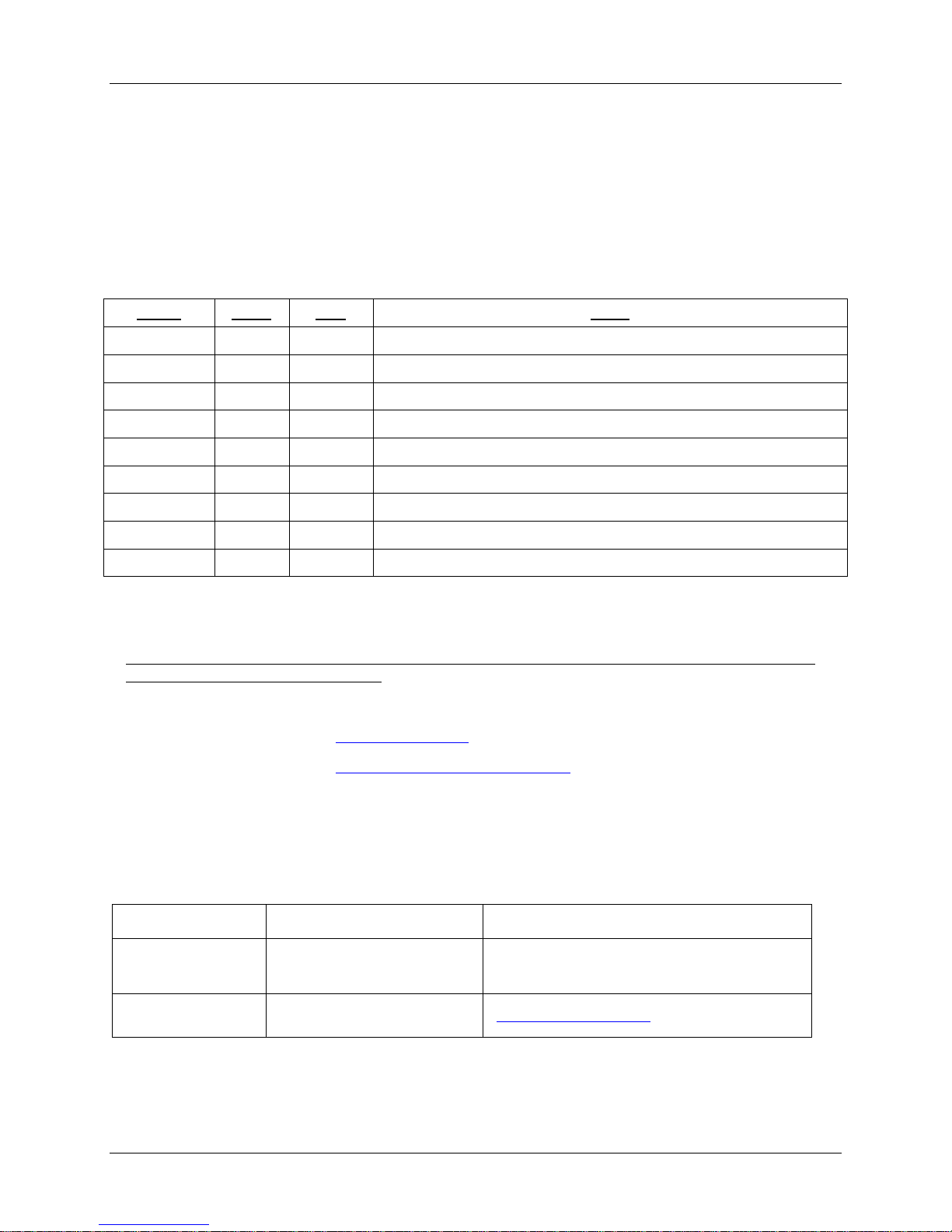
Revision Notes
The following list provides notes concerning all revisions of this document.
Doc ID
Rel ID
Date
Notes
34-ST-25-19
Rev. 0
11/28
First issue of document.
34-ST-25-19
Rev. 1
6/25/04
Revised Appendix A, ATEX Directive 94/9/EC
34-ST-25-19
Rev. 2
8/19/05
Revised Appendix A, D
34-ST-25-19
Rev. 3
9/1/05
Revised Appendix C
34-ST-25-19
Rev. 4
5/08
Remove STT150 References, added EU Meter and Updated Appendices
34-ST-25-19
Rev. 5
12/08
IECEx certification added
34-ST-25-19
Rev. 6
10/09
CSA updates, table 1
34-ST-25-19
Rev. 7
May 2011
SAEx and ATEX approvals added
34-ST-25-19
Rev. 8
July 2017
SM and DM meters removed. EU Declaration added. ATEX updated.
Support and Contact Information
For Europe, Asia Pacific, North and South America contact details, refer to the back page of this manual or the
appropriate Honeywell Support web site:
Honeywell Corporate www.honeywell.com
Honeywell Process Solutions https://www.honeywellprocess.com/*
Telephone and Email Contacts
Area
Organization
Phone Number
United States and
Canada
Honeywell Inc.
1-800-343-0228 Customer Service
1-800-423-9883 Global Technical Support
Global Email
Support
Honeywell Process Solutions
ask-ssc@honeywell.com
iv RMA 3000 Remote Meter Assemblies User Manual Release 8
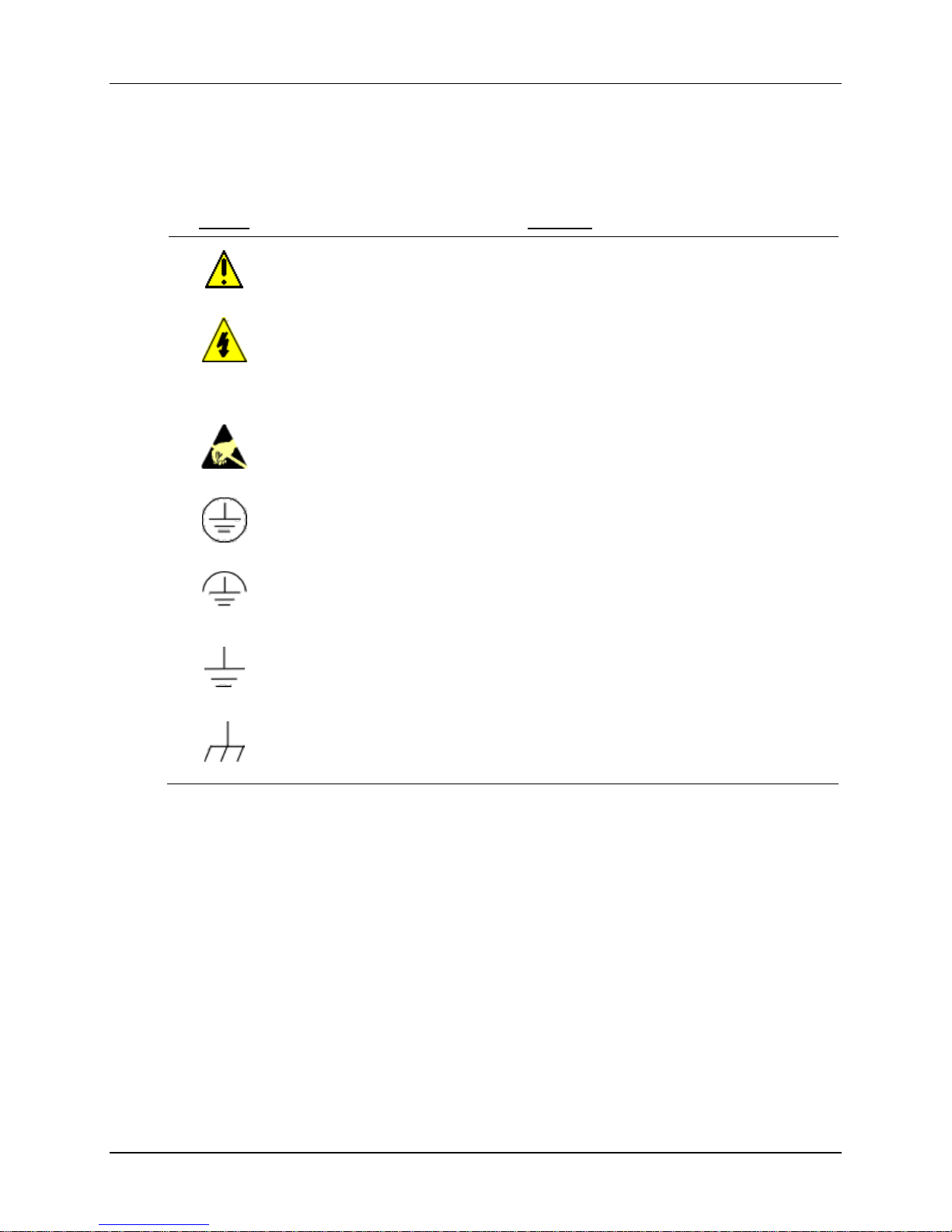
Symbol Definitions
The following table lists those symbols used in this document to denote certain conditions.
Symbol
Definition
This CAUTION symbol on the equipment refers the user to the Product Manual for
additional information. This symbol appears next to required information in the manual.
WARNING
PERSONAL INJURY: Risk of electrical shock. This symbol warns the user of a
potential shock hazard where HAZARDOUS LIVE voltages greater than 30 Vrms, 42.4
Vpeak, or 60 VDC may be accessible. Failure to comply with these instructions
could result in death or serious injury.
ATTENTION, Electrostatic Discharge (ESD) hazards. Observe precautions for
handling electrostatic sensitive devices
Protective Earth (PE) terminal. Provided for connection of the protective earth (green
or green/yellow) supply system conductor.
Functional earth terminal. Used for non-safety purposes such as noise immunity
improvement. NOTE: This connection shall be bonded to protective earth at the
source of supply in accordance with national local electrical code requirements.
Earth Ground. Functional earth connection. NOTE: This connection shall be bonded to
Protective earth at the source of supply in accordance with national and local electrical
code requirements.
Chassis Ground. Identifies a connection to the chassis or frame of the equipment shall
be bonded to Protective Earth at the source of supply in accordance with national and
local electrical code requirements.

Release 8 RMA 3000 Remote Meter Assemblies User Manual v
Contents
Support and Contact Information ....................................................................................................... iii
Telephone and Email Contacts .......................................................................................................... iii
CE Conformity (Europe) Notice for Remote Meter Assemblies (RMA) ..................... vii
About Conformity and Special Conditions ......................................................................................... vii
RMA 3000 Description ............................................................................................... 8
Function and Design ............................................................................................................................ 8
Meter Types - Options ..................................................................................................................... 9
Installation in Hazardous Locations ................................................................................................... 11
Wiring-Port Seals at Remote Housing ........................................................................................... 11
Specific Parameters of the Mode of Protection (Intrinsic Safety) .................................................. 12
Approvals/Certifications ................................................................................................................. 12
Approvals for Specific Configurations – Certified Drawings .......................................................... 14
List of Certified Engineering Drawings – Wiring Diagrams ............................................................ 15
Wiring Drawings - Overview........................................................................................................... 17
Installation in Non-Hazardous Locations ........................................................................................... 19
Multiple Remote Meters ................................................................................................................. 19
Appendix A – PRODUCT CERTIFICATIONS .......................................................... 20
Marking and Inscriptions ................................................................................................................ 21
A1. European Directive Information (CE Mark) ................................................................................. 24
A2. Hazardous Location Wiring ......................................................................................................... 27
North America ................................................................................................................................ 27
Cable Systems for Division 1 / Zone 1 and Division 2 / Zone 2..................................................... 27
A3. Hazardous Locations Certification .............................................................................................. 29

vi RMA 3000 Remote Meter Assemblies User Manual Release 8
Tables
Table 1: Certified Engineering Drawings – Wiring Diagrams 15
Table 2: Wiring Overview: ME/ST 3000 transmitter with or without HART Option 18
Table 3: FM Approvals 29
Table 4: Canadian Standards Association (CSA Certification) 31
Table 5: ATEX Approvals 33
Table 6: IECEx Approvals 34
Table 7: South Africa- SAEx S/09-341X 35
Figures
Figure 1: Overview of RMA Configuration 8
Figure 2: Highlights of Meter Features 9
Figure 3: Examples of Typical Conduit Fittings 11
Figure 4: Example of Sealed Cable Gland 11
Figure 5: RMA 3000 Intrinsic Safety Parameters 12
Figure 6: Stylized Sample of Certified Engineering Drawing 14
Figure 7: Legend for Wiring Diagrams Overview 17

Release 8 RMA 3000 Remote Meter Assemblies User Manual vii
CE Conformity (Europe) Notice for Remote Meter Assemblies
(RMA)
About Conformity and Special Conditions
This product is in conformity with the protection requirements of 89/336/EEC, the EMC Directive, and of
94/9/EC, the Explosive Atmospheres (ATEX) Directive. Conformity of this product with any other “CE
Mark” Directive(s) shall not be assumed.
Deviation from the installation conditions specified in this manual, and the following special conditions,
may invalidate this product’s conformity with the EMC Directive.
• Shielded, twisted-pair cable such as Belden 9318 must be used for all signal/power wiring.
• The shield must be connected to ground at only one end of the cable. Connect it to the power supply and
the meter sides of the wiring; leave the shield insulated at the transmitter side of the wiring.
ATTENTION
The emission limits of EN 50081-2 are designed to provide reasonable protection against
harmful interference when this equipment is operated in an industrial environment. Operation
of this equipment in a residential area may cause harmful interference. This equipment
generates, uses, and can radiate radio frequency energy and may cause interference to radio
and television reception when the equipment is used closer than 30 meters (98 feet) to the
antenna(e). In special cases, when highly susceptible apparatus is used in close proximity, the
user may have to employ additional mitigating measures to further reduce the electromagnetic
emissions of this equipment.
viii RMA 3000 Remote Meter Assemblies User Manual Release 8
RMA 3000 Description
Function and Design
The Honeywell RMA 3000 Remote Meter Assemblies provide various means of remote-mounting a meter
that is associated with a Honeywell SmartLine transmitter or a compatible non-Honeywell transmitter.
The RMA 3000 includes a remote meter housing that can be used in hazardous environments or in ordinary
environments. When used in hazardous environments, the remote housing must be configured as a
flameproof/explosion-proof housing, in which all points of entrance and exit for wiring are protected and
sealed via rigid metal conduit or suitable cable gland fittings.
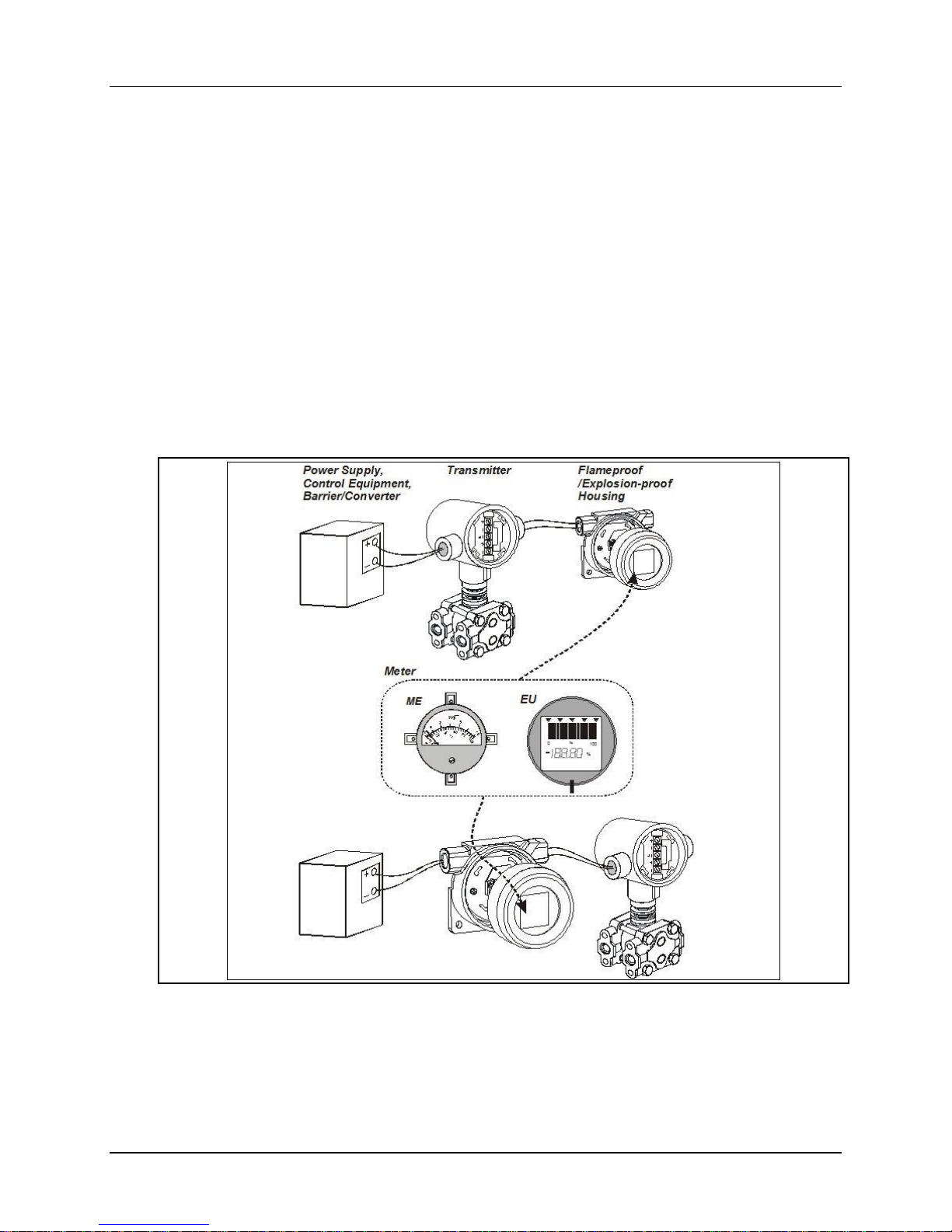
Two meter styles are available, and with a few exceptions any of these may be connected in either of two
basic physical/wiring configurations, as indicated in Figure 1.
Figure 1: Overview of RMA Configuration
Release 8 RMA 3000 Remote Meter Assemblies User Manual 9
That is, the explosion-proof housing may be located
- at the end of a wiring run for the transmitter loop, or
- between the transmitter and the receiver devices.
This manual includes several sets of Honeywell-certified engineering drawings that specify RMA 3000
configurations and conditions that are approved for use in hazardous environments by various approval
agencies (FM, CSA, and LCIE (ATEX). Each of these drawings shows a configuration similar to that
shown in Figure 1; that is, a single meter connected remote from a single transmitter.
In some selected cases (such as operation in non-hazardous locations), it is possible to connect more than
one meter to a given transmitter. In these cases, the additional meter(s) may be placed either at the end of a
wiring run, or at any location between the transmitter and other elements of the Remote Meter Assemblies
configuration.
The number of meters that may be incorporated depends on the circuit configuration and on electrical
characteristics of associated equipment. For more information regarding the use of multiple remote meters
with a single transmitter, refer to the descriptions under the heading Multiple Remote Meters.
Meter Types - Options
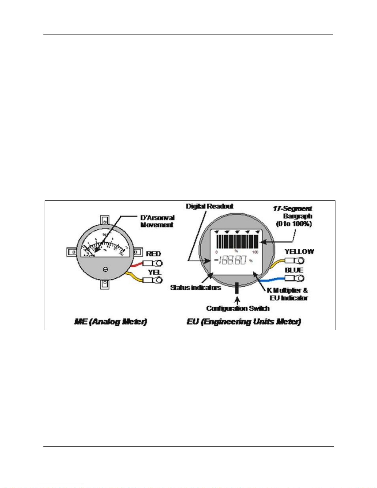
Remote Meter Assemblies provide for two meter types. The features of each are highlighted in Figure 2,
and are described after the figure below.
Figure 2: Highlights of Meter Features
ME – Analog Meter
Function - The ME is an analog device that functions as an output indicator for any transmitter that
operates in the 4-20 mA current mode.
Application - The ME can be used as a Remote Meter Assembly component with any one of the
following SmartLine transmitters operating in the analog (4 to 20 mA) mode.
Electrical Characteristics – The ME is an electromechanical device of the D’Arsonval type. That is,
the current passing through a coil in the meter is used to deflect a needle to indicate the magnitude of the
current, where a current of 4-20 mA represents 0% to 100%.
The ME can be used in combination with the SM in the same loop, provided that the formula presented
under the SM description above in electrical characteristics for multiple meters is obeyed.

10 RMA 3000 Remote Meter Assemblies User Manual Release 8
EU – Engineering Units Meter
The Engineering Units Meter (EU) is described briefly here only in the context of RMA 3000 application
and installation. For detailed information such as digital display features, installation, set up and operation,
refer to
34-ST-25-18 Engineering Unit Meter User’s Guide.
Function - The Engineering Unit Meter is an LCD indicator that provides a digital display of a
transmitter’s output PV when connected in a 4 to 20 mA analog loop. The meter is compatible with
Honeywell SmartLine transmitters operating in analog mode and with other non-Honeywell transmitters
operating in a 4 to 20 mA current loop.
Description - The EU meter is designed to provide a simple indication of a transmitter’s output value. A
multi-segmented LCD display is encased in a circular black plastic frame for local installation to the
transmitter. A printed circuit assembly (PWA) is mounted behind the display and contains the electronics
and wire connections for the meter. The EU meter is powered from the transmitter loop current. A
momentary contact toggle switch is mounted on the PWA and is used for setting up and verifying the
display indication.
Release 8 RMA 3000 Remote Meter Assemblies User Manual 11
Installation in Hazardous Locations
For installation in hazardous locations, the RMA 3000 must be configured and installed as detailed in the
appropriate Honeywell-certified engineering drawing(s), which conform to practices specified by various
approval agencies. Installation requirements vary somewhat among approval agencies.
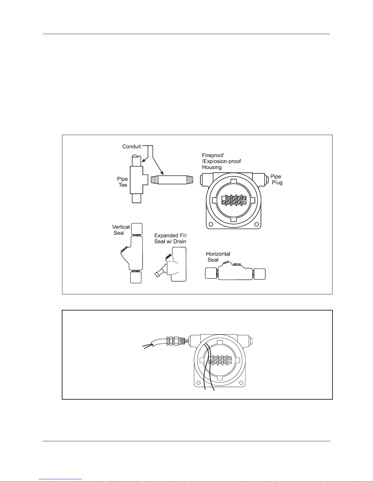
Wiring-Port Seals at Remote Housing
When used in hazardous environments, the remote housing may be configured as a flameproof/explosionproof housing, in which all points of entrance and exit for wiring are protected and sealed via rigid metal
conduit or suitable cable gland fittings.
Examples of metal conduit fittings are shown in Figure 3, and an example of a sealed cable gland is shown
in Figure 4.
Figure 3: Examples of Typical Conduit Fittings
Hawke ICG 623 EEx d/EEx e
½ NPT, Sealing (Non-Armored)
Figure 4: Example of Sealed Cable Gland
 Loading...