

RM7897A,C 7800 SERIES
Relay Modules
INSTALLATION INSTRUCTIONS
APPLICATION
The RM7897A,C are microprocessor-based integrated
burner controls for automatically fired gas, oil, or
combination fuel single burner applications. The
RM7897A,C system consist of a relay module, subbase,
amplifier, and purge card. Options include: 2-line VFD (see
document 65-0090) or 4-line LCD (see document 32-
00110) Keyboard Display Module, Data ControlBus™
Module, remote display mounting, Expanded Annunciator
or Modbus module.
Functions provided by the RM7897A,C include automatic
burner sequencing, flame supervision, system status
indication, system or self-diagnostics and
troubleshooting.
The RM7897 adds a proof of closure input to the standard
primary control function of the RM7895/RM7896
product. It adds a blinking fault code function to the
POWER LED on Alarm shutdown. It also adds
programmable postpurge using the S7800A1142
Keyboard Display Module (KDM).
The RM7897A1002 offers selectable pilot operation,
intermittent on terminal 8 or interrupted on terminal 21.
The RM7897C1000 offers interrupted pilot and delayed
main valve for 2-step firing (Low-High-Low) applications.
The RM7897C1018 has 4 second MFEP (main flame
establishing period).
The RM7897C1026 provides a special recycle function for
configuration of Jumper JR2:
— JR 2 intact: Recycle on loss of flame.
— JR2 clipped: If flame loss occurs during the first 15
seconds in the Run period, then lockout occurs. If
flame loss occurs after 15 seconds into the Run
period, then recycle.
Factory default for Post Purge time: 15 seconds.
This document provides installation and static checkout
instructions. Other applicable publications are:
Publication
No. Product
32-00110 S7800A2142 4-line LCD Keyboard Display
Module Product Data
65-0084 Q7800A,B 22-Terminal Wiring Subbase
Product Data
65-0288 S7800A1142 Keyboard Display Module
Product Data
65-0091 S7810A Data ControlBus Module™ Product
Data
65-0095 S7820 Remote Reset Module Product Data
65-0097 221729C Dust Cover Installation
Instructions
65-0101 S7830 Expanded Annunciator Product Data
65-0109 R7824, R7847, R7848, R7849, R7851,
R7852, R7861, R7886 Flame Amplifiers for
the 7800 Series Product Data
65-0131 221818A Extension Cable Assembly
Product Data
65-0229 7800 SERIES Relay Modules Checkout and
Troubleshooting Product Data.
This document covers the following 7800 Series Relay
Modules:
• RM7897A1002
• RM7897A2002
• RM7897C1000
• RM7897C2000
SPECIFICATIONS
Electrical Ratings (See Table 3):
Voltage and Frequency:
RM7897A,C: 120 Vac (+10/-15%), 50/60 Hz (± 10%).
Power Dissipation: 10W maximum.
Maximum Total Connected Load: 2000 VA.
Fusing Total Connected Load: 15A Fast Blow, type SC or
equivalent.
SIL
3
Capable
Environmental Ratings:
Ambient Temperature:
Operating: -40°F to 140°F (-40°C to +60°C).
Storage: -40°F to 150°F (-40°C to +66°C).
32-00158-03

RM7897A,C 7800 SERIES RELAY MODULES
Humidity: 85% relative humidity continuous, noncon-
densing.
Vibration: 0.5G environment.
SIL 3 Capable:
SIL 3 Capable in a properly designed Safety Instru-
mented System. See form 65-0312 for Certificate
Agreement
Approvals:
Underwriters Laboratories Inc. Listed: File No. MP268,
Guide No. MCCZ.
Factory Mutual Approved: Report No. 1V9A0.AF.
Swiss RE (formerly IRI): Acceptable.
Federal Communications Commission: Part 15, Class
B, Emissions.
INSTALLATION
When Installing this Product…
1. Read these instructions carefully. Failure to follow
them could damage the product or cause a
hazardous condition.
2. Check the ratings given in the instructions and
marked on the product to make sure the product is
suitable for the application.
3. Installer must be a trained, experienced, flame
safeguard service technician.
4. After installation is complete, check out the product
operation as provided in these instructions.
WARNING
Fire or Explosion Hazard.
Can cause severe injury, death or property
damage.
Follow applicable safety requirements when
installing a control on a burner to prevent death or
severe injury.
WARNING
Electrical Shock Hazard.
Can cause serious injury, death or equipment
damage.
Disconnect power supply before beginning
installation. More than one disconnect may be
required.
IMPORTANT
1. Wiring connections for the relay modules are
unique; refer to Fig. 2 and 3 or the appropriate
Specifications for proper subbase wiring.
2. Wiring must comply with all applicable codes,
ordinances and regulations.
3. Wiring must comply with NEC Class 1 (Line Volt-
age) wiring.
4. Loads connected to the RM7897A,C must not
exceed those listed on the RM7897A,C label or the
Specifications; see Table 1.
5. Limits and interlocks must be rated to simultane-
ously carry and break current to the ignition transformer, pilot valve, and main fuel valve(s).
6. All external timers must be listed or
component-recognized by authorities who have
proper jurisdiction.
7. For on-off gas-fired systems, some authorities
who have jurisdiction prohibit the wiring of any
limit or operating contacts in series between the
flame safeguard control and the main fuel valve(s).
8. Two flame detectors can be connected in parallel
with the exception of Flame Detectors C7015,
C7915, C7927, C7961 and C7952.
9. This equipment generates, uses and can radiate
radio frequency energy and, if not installed and
used in accordance with the instructions, can
cause interference with radio communications. It
has been tested and found to comply with the
limits for a Class B computing device of Part 15 of
FCC rules, which are designed to provide
reasonable protection against such interference
when operated in a commercial environment.
Operation of this equipment in a residential area
may cause interference, in which case, the users,
at their own expense, may be required to take
whatever measures are required to correct this
interference.
10. This digital apparatus does not exceed the Class B
limits for radio noise for digital apparatus set out
in the Radio Interference Regulations of the Canadian Department of Communications.
Location
Humidity
Install the relay module where the relative humidity never
reaches the saturation point. The relay module is designed
to operate in a maximum 85% relative humidity
continuous, noncondensing, moisture environment.
Condensing moisture can cause a safety shutdown.
Vibration
Do not install the relay module where it can be subjected
to vibration in excess of 0.5G continuous maximum
vibration.
Weather
The relay module is not designed to be weather tight.
When installed outdoors, protect the relay module in an
approved weather-tight enclosure.
Mounting Wiring Subbase
1. Mount the subbase in any position except horizon-
tally with the bifurcated contacts pointing down. The
standard vertical position is recommended. Any
other position decreases the maximum ambient
temperature rating.
2. Select a location on a wall, burner or electrical panel.
The Q7800 can be mounted directly in the control
cabinet. Be sure to allow adequate clearance for servicing, installation, access or removal of the relay
module, Expanded Annunciator, Keyboard Display
Module, flame amplifier, flame amplifier signal voltage probes, Run/Test Switch, electrical signal voltage probes and electrical field connections.
32-00158—03 2

RM7897A,C 7800 SERIES RELAY MODULES
3. For surface mounting, use the back of the subbase
as a template to mark the four screw locations. Drill
the pilot holes.
4. Securely mount the subbase using four no. 6 screws.
Wiring Subbase
NOTE: There are several different subbase models that
Series 1000 Subbase
All relay product codes that start with a 1 (example:
RM7840G
Q7800A1005/U. These relays can also be used on the
Series 2000 subbase noted below.
Series 2000 Subbase
All relay product codes that start with a 2 (example:
RM7840G
Q7800A2005/U.
Subbase Compatibility
Any relay module in the 1000 series is fully backward
compatible with any subbase already installed in the field
(Q7800A1005/U, Q7800B1003/U, Q7800A2005/U,
Q7800B2003/U).
Any relay module in the new 2000 series will only be able
to be installed on subbase Q7800A2005/U, and will not be
backward compatible with any Q7800A1005/U legacy
subbases already installed in the field.
can be purchased. It is important to note which
subbase is compatible with the relay module
when purchasing repair or replacement parts.
1014/U) can be used with existing subbase
2014/U) can be used with subbase
IMPORTANT
Make sure to check the relay model number and
check the subbase compatibly prior to ordering or
attempting a new installation or field upgrade.
If you attempt to place a 2000 series relay on a
non-compatible 1000 series subbase, you will
receive an error code of 101. This indicates that
you must a) change out the subbase to a
Q7800A2005/U or b) chose a compatible 1000
series relay module.
WARNING
Electrical Shock Hazard.
Can cause severe injury, death or equipment
damage.
Disconnect the power supply before beginning
installation. More than one disconnect may be
required.
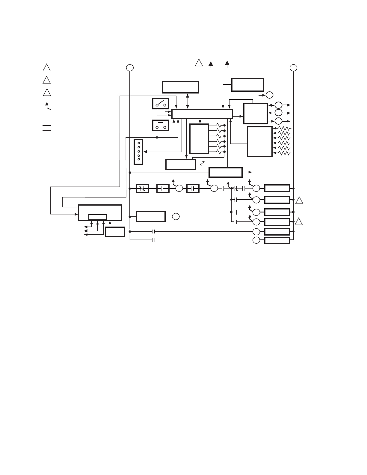
The internal block diagram of the RM7897A,C is shown in
Fig. 1.
1. For proper subbase wiring and sequence chart, refer
to Fig. 2 and 3.
2. For remote wiring of the Keyboard Display Module,
refer to the Specifications for the Keyboard Display
Module. There are two options for the separately
purchased display: 2-line VFD display (65-0090) or
a 4-line LCD display (32-00110), Data ControlBus™
Module (65-0091) or Extension Cable Assembly (65-
0131).
3. Disconnect the power supply from the main disconnect before beginning installation to prevent electrical shock and equipment damage. More than one
disconnect can be required.
4. All wiring must comply with all applicable electrical
codes, ordinances and regulations. Wiring, where
required, must comply with NEC, Class 1 (Line Voltage) wiring.
5. For recommended wire size and type, see Table 1.
6. For recommended grounding practices, see Table 2.
3 32-00158—03
RM7897A,C 7800 SERIES RELAY MODULES
PROVIDE DISCONNECT MEANS AND
1
OVERLOAD PROTECTION AS REQUIRED.
2
RM7897A-INTERMITTENT PILOT.
RM7897C-INTERRUPTED PILOT.
3
RM7897A-INTERRUPTED PILOT.
RM7897C-DELAYED MAIN VALVE.
INDICATES FEEDBACK SENSING
TO RELAY STATUS FEEDBACK
AND LINE VOLT INPUTS
FIELD WIRING
INTERNAL WIRING
OPTIONAL KEYBOARD
DISPLAY MODULE
DDL
DDL
COMMUNICATIONS
M22727A
1
RS485
2
3
REMOTE
RESET
5
RUN/TEST
SWITCH
RESET
PUSHBUTTON
STATUS LEDs
LIMITS
PREIGNITION
INTERLOCK
CONFIGURATION
JUMPERS
CONTROLLER
6K1
3K1
MICROCOMPUTER
SAFETY RELAY
CIRCUIT
6
LOCKOUT
INTERLOCK
(INCLUDING
AIRFLOW SWITCH)
20
1
RELAY
DRIVE
CIRCUIT
120 VAC,
50/60 HZ
L1
(HOT)
2K
3K
4K
5K
6K
7K
1K
POWER SUPPLY
1K1 2K1 5K1
7
L2
PLUG-IN PURGE
TIMER CARD
FLAME SIGNAL
PLUG-IN
TEST
FLAME
AMPLIFIER
4K1
2K2
7K16
RELAY
STATUS
FEEDBACK
AND LINE
VOLTAGE
INPUTS
CONTROL
POWER
10
8
9
21
4
3
TEST
JACK
F
G
22
IGNITION
PILOT
MAIN VALVE
BLOWER
ALARM
L2
2
3
Fig. 1. Internal block diagram of RM7897A,C (see Fig. 2 and 3 for detailed wiring instructions).
7. Recommended wire routing of leadwires:
a. Do not run high voltage ignition transformer
wires in the same conduit with the flame
detector, Data ControlBus Module™, or Remote
Reset Module wiring.
b. Do not route flame detector, Data ControlBus™
Module, or Remote Reset Module leadwires in
conduit with line voltage circuits.
c. Enclose flame detector leadwires without armor
cable in metal cable or conduit.
d. Follow directions in flame detector, Data
ControlBus™ Module, or Remote Reset Module
Instructions.
8. The KDM is powered from a low voltage, energy limited source. It can be mounted outside of a control
panel if it is protected from mechanical damage.
NOTE: A 13 Vdc power supply must be used any time
more than one KDM is used.
32-00158—03 4
LINE VOLTAGE ALARM
BURNER MOTOR
(BLOWER)
BURNER
CONTROLLER/LIMITS
RUNNING INTERLOCK
(INCLUDING
AIRFLOW SWITCH)
LED
DISPLAY
BURNER
OPERATING
CONTROLS
AND
INTERLOCKS
FLAME
SIGNAL
INTERMITTENT
PILOT/IGNITION
MAIN FUEL VALVE(S)
IGNITION
FLAME DETECTOR
3
INITIATE
(INITIAL
POWERUP
ONLY)
POWER
PREIGNITION INTERLOCK CLOSED
STANDBY
LIMITS AND BURNER CONTROLLER CLOSED
SAFE START CHECK
Q7800
G
L2
3
4
(L1)
5
6
7
8
9
10
F
POWER
5
00
TIMED
PREPURGE
POWER
PILOT
FLAME
MAIN
BURNER/BLOWER MOTOR
10
RUNNING INTERLOCKS CLOSED
FOR DIRECT SPARK IGNITION
12
(OIL OR GAS)
13
14
15
16
17
2
18
19
PREIGNITION
20
INTERLOCK
21
22
PFEP
10 SEC.
00
(4 SEC. IF
JR1
INTERRUPTED PILOT
10
CLIPPED
POWER
PILOT
FLAME
MAIN
IGN.
20TO5
IGNITION
10
TRANSFORMER
8
MAIN VALVE
MASTER
SWITCH
20
MFEP
POWER
PILOT
FLAME
MAIN
ALARMALARMALARM
4
8 INTERMITTENT PILOT
8
21
21
MAIN VALVE
TO
6
L1
7TO
6
FLAME PROVING
RM7897A,C 7800 SERIES RELAY MODULES
L2
10-SECOND
INTERRUPTED
PILOT
L1
(HOT)
1
L2
00
RUN
POWER
PILOT
FLAME
MAIN
ALARM
9
4
POSTPURGE
POWER
STANDBY
POWER
PII
SSC
1
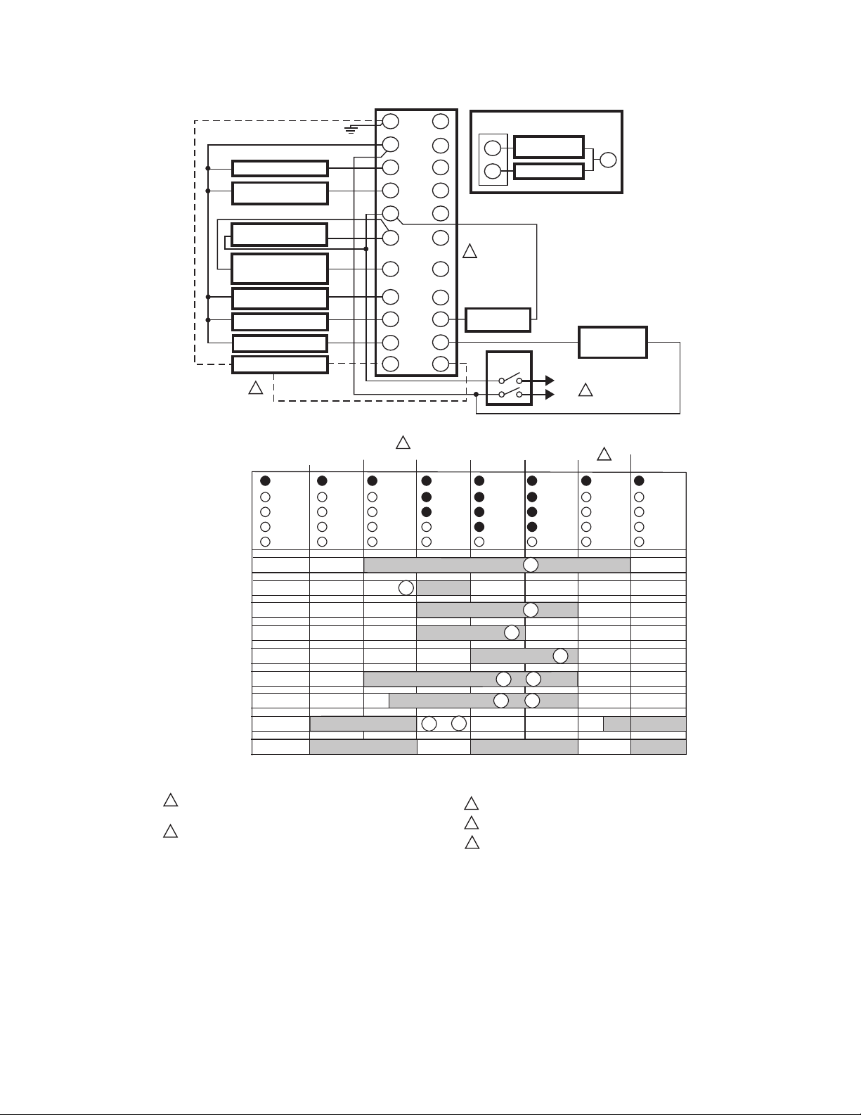
120 VAC, 50/60 HZ POWER SUPPLY. PROVIDE DISCONNECT MEANS
AND OVERLOAD PROTECTION AS REQUIRED.
DO NOT CONNECT ANY WIRES TO UNUSED TERMINALS.
2
Fig. 2. Wiring subbase and sequence chart for RM7897A.
SEE FLAME DETECTOR SPECIFICATIONS FOR CORRECT WIRING.
3
PROGRAMMED ON SETUP USING S7800A1142 DISPLAY.
4
PURGE TIME DEPENDS ON WHICH ST7800 IS INSTALLED.
5
M22728C
5 32-00158—03
RM7897A,C 7800 SERIES RELAY MODULES
LINE VOLTAGE
ALARM
BURNER MOTOR
(BLOWER)
BURNER
CONTROLLER/LIMITS
RUNNING INTERLOCK
(INCLUDING
AIRFLOW SWITCH).
10 SEC. INTERRUPTED
PILOT/IGNITION
MAIN FUEL VALVE(S)
IGNITION
FLAME DETECTOR
4
L2
10
Q7800
G
3
4
5
6
7
8
9
F
(L1)
12
13
14
15
16
17
18
19
20
21
22
FOR DIRECT SPARK IGNITION
(OIL OR GAS)
IGNITION
10
TRANSFORMER
8
9
MAIN VALVE
2
DELAYED
(2ND STAGE)
MAIN VALVE
MASTER
SWITCH
L1
(HOT)
L2
PREIGNITION
INTERLOCK
1
L2
INITIATE
(INITIAL
POWERUP
ONLY)
POWER
LED
DISPLAY
BURNER
OPERATING
CONTROLS
AND
INTERLOCKS
FLAME
SIGNAL
1
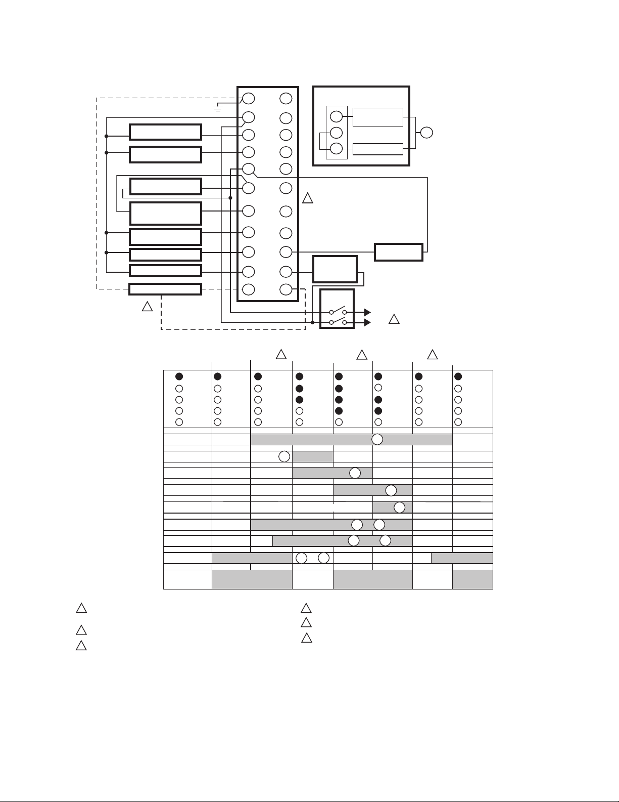
120 VAC, 50/60 HZ POWER SUPPLY. PROVIDE DISCONNECT MEANS
AND OVERLOAD PROTECTION AS REQUIRED.
2
DO NOT CONNECT ANY WIRES TO UNUSED TERMINALS.
3
PROGRAMMABLE POST PURGE TIMING USING S7800A1142 KDM.
STANDBY
LIMITS AND BURNER CONTROLLER CLOSED
PREIGNITION INTERLOCK CLOSED
00 00 10
TIMED
PREPURGE
POWER
SAFE START CHECK
PFEP
10 SEC.
5
(4 SEC. IF
CLIPPED
JR1
POWER
PILOT
FLAME
MAIN
POWER
PILOT
FLAME
MAIN
BURNER/BLOWER MOTOR
10
IGNITION
INTERRUPT/PILOT
RUNNING INTERLOCK
5
TO
4
5
6
RUN
POWER
PILOT
FLAME
MAIN
ALARM
9
21
7
00
3
POSTPURGE
POWER
STANDBY
POWER
PII
SSC
M22729C
20
6
MFEP
POWER
PILOT
FLAME
MAIN
ALARMALARMALARM
4
8
MAIN VALVE
DELAYED MAIN VALVE
6
L1
TO
6
TO
20
FLAME PROVING
SEE FLAME DETECTOR SPECIFICATIONS FOR CORRECT WIRING.
PURGE TIME DEPENDS ON WHICH ST7800 IS INSTALLED.
RM7897C1018 IS 14 SECONDS FOR 4 SECOND MFEP.
Fig. 3. Wiring subbase and sequence chart for RM7897C.
32-00158—03 6

RM7897A,C 7800 SERIES RELAY MODULES
Table 1. Recommended Wire Sizes and Part Numbers.
Application Recommended Wire Size Recommended Part Numbers
Line voltage terminals. 14, 16 or 18 AWG copper conductor, 600 volt
Keyboard Display Module 22 AWG two-wire twisted pair with ground, or five-
Data ControlBus™
Module
Remote Reset Module 22 AWG two-wire twisted pair, insulated for low
13 Vdc full-wave rectified
transformer power input.
a
Earth ground (subbase and relay
module).
Signal ground (Keyboard Display
Module, Data ControlBus™ Module.
10. Be sure loads do not exceed the terminal ratings.
a
The KDM or Data ControlBus™ Module (for remote mounting or communications) must be wired in daisy chain configuration, 1(a)-1(a), 2(b)-2(b), 3(c)-3(c). The order of interconnection of all the devices listed above is not important. Be
aware that modules on the closest and farthest end of the daisy chain configuration string require a 120 ohm (1/4 watt
minimum) resistor termination across terminals 1 and 2 of the electrical connectors for connections over 100 feet (31
meters).
Ground Type Recommended Practice
9. Maximum wire lengths:
a. RM7897A,C leadwires: The maximum leadwire
length is 300 feet to terminal inputs (Control,
Running/Lockout Interlock).
b. Flame Detector leadwires: The maximum flame
sensor leadwire length is limited by the flame
signal strength.
c. Remote Reset leadwires: The maximum length of
wire is 1000 feet (305 meters) to a Remote Reset
push button.
d. Data ControlBus Module™: The maximum Data
ControlBus™ Module cable length depends on
the number of system modules connected, the
noise conditions and the cable used. The
maximum length of all Data ControlBus™
Module interconnecting wire is 4000 feet (1219
meters).
Refer to the label on the RM7897A,C or to the terminal ratings in Table 3.
insulation, moisture-resistant wire.
wire.
22 AWG two-wire twisted pair with ground, or fivewire.
voltage.
18 AWG wire insulated for voltages and
temperatures for given application.
Table 2. Recommended Grounding Practices.
1. Use to provide a connection between the subbase and the control panel of the
equipment. Earth ground must be capable of conducting enough current to
blow the
15A, type SC,. fast blow fuse (or breaker) in the event of an internal short circuit.
2. Use wide straps or brackets to provide minimum length, maximum surface area
ground conductors. If a leadwire is required, use 14 AWG copper wire.
3. Make sure that mechanically tightened joints along the ground path are free of
nonconductive coatings and protected against corrosion on mating surfaces.
Use the shield of the signal wire to ground the device to the signal ground terminal
3(c) of each device. Connect the shield at both ends of the daisy chain to earth
ground.
Final Wiring Check
1. Check the power supply circuit. The voltage and
frequency tolerance must match those of the
RM7897A,C. A separate power supply circuit can be
required for the RM7897A,C. Add the required
disconnect means and overload protection.
2. Check all wiring circuits and complete Static
Checkout in Table 6 before installing the
RM7897A,C on the subbase.
3. Install all electrical connectors.
4. Restore power to the panel.
STATIC CHECKOUT
After checking all wiring, perform this checkout before
installing the RM7897A,C on the subbase. These tests
verify the Q7800 Wiring Subbase is wired correctly, and
the external controllers, limits, interlocks, actuators,
valves, transformers, motors and other devices are
operating properly.
TTW60C, THW75C, THHN90C.
Belden 8723 shielded cable or
equivalent.
Belden 8723 shielded cable or
equivalent.
—
TTW60C, THW75C, THHN90C.
7 32-00158—03

RM7897A,C 7800 SERIES RELAY MODULES
Table 3. Terminal Ratings.
Ratings
Terminal Number Description
RM7897A,C
G Flame Sensor Ground —
Earth G
Earth Ground
a
—
L2(N) Line Voltage Common —
3 Alarm 120 Vac, 1A pilot duty.
4 Burner Motor 120 Vac, 9.8A AFL, 58.8 ALR (inrush).
5 Line Voltage Supply (L1)
120 Vac (+10/-15%), 50 or 60 Hz (±10%).
6 Burner Controller and Limits 120 Vac, 1 mA.
7 Lockout Interlock 120 Vac, 8A run, 43A inrush.
8 Pilot Valve/Ignition
9 Main Fuel Valve
10 Ignition
120 Vac
120 Vac
120 Vac
c
c
c
F(11) Flame Sensor 60 to 220 Vac, current limited.
12 to 19 — —
20 PreIgnition Interlock 120 Vac, 1 mA.
21 Interrupted Pilot (RM7897A) 120 Vac
21 2nd Stage Main Valve (RM7897C)
120 Vac
c
22 Shutter 120 Vac, 0.5A
a
See Table 2.
b
2000 VA maximum load connected to RM7897A,C Assembly.
c
See Tables 4 and 5.
b
Table 4. Combinations for Terminals 8, 9, 10 and 21.
Interrupted Pilot Valve
Combination
Number Pilot Fuel 8 Main 9 Ignition 10
(RM7897A Only)
21
Delayed Main Valve
21 (RM7897C Only)
1 C F No Load C No Load
2 B F No Load B No Load
3
a
F
F A F No Load
4 F F A F No Load
5
a
F
FA F F
6 D F A D No Load
7
a
D
DA D D
8 D D A D No Load
9
a
RM7897C only, jumper terminals 8 to 9.
a
D
No Load A D D
Table 5. Composition of each Combination.
ABCDF
4.5A ignition 50 VA Pilot Duty plus
4.5A ignition.
180 VA Ignition plus
motor valves with:
660 VA inrush,
360 VA open,
240 VA hold.
2A Pilot Duty 65 VA Pilot Duty plus
motor valves with:
3850 VA inrush,
700 VA open,
250 VA hold.
32-00158—03 8

WARNING
Fire or Explosion Hazard.
Can cause property damage, severe injury
or death.
Close all manual fuel shutoff valve(s) before
starting these tests.
Use extreme care while testing the system. Line
voltage is present on most terminal connections
when power is on.
Ensure proper selection of configuration jumpers before
starting the burner operation.
RM7897A,C 7800 SERIES RELAY MODULES
6. If there is no voltage or the operation is abnormal,
check the circuits and external devices as described
in the last column.
7. Check all wiring for correct connections, tight terminal screws, correct wire, and proper wiring techniques. Replace all damaged or incorrectly sized
wires.
8. Replace faulty controllers, limits, interlocks, actuators, valves, transformers, motors and other devices,
as required.
9. Make sure normal operation is obtained for each
required test before continuing the checkout.
10. After completing each test, be sure to open the
master power switch and remove the test jumper(s)
before proceeding to the next test.
CAUTION
Electrical Hazard.
Can cause equipment damage or failure.
Do not perform a dielectric test with the relay
module installed. Internal surge protectors can
break down, allowing relay module to fail the
dielectric test and destroy the internal lightning
and high current protection.
1. Open the master switch before installing or removing a jumper on the subbase.
2. Before continuing to the next test, be sure to remove
the test jumper(s) used in the previous test.
3. Replace all limits and interlocks that are not operating properly. Do not bypass limits and interlocks.
Equipment Recommended
1. Voltmeter (1M ohm/volt minimum sensitivity) set on
the 0 to 300 Vac scale.
2. Two jumper wires, no. 14 wire, insulated, 12 in.
(304.8 mm) long with insulated alligator clips at
both ends.
General Instructions
1. Perform all applicable tests listed in Static Checkout,
Table 6, in the order listed.
2. Make sure all manual fuel shutoff valve(s) are
closed.
3. For each test, open the master switch and install the
jumper wire(s) between the subbase wiring terminals listed in the Test Jumpers column.
4. Close the master switch before observing operation.
5. Read the voltage between the subbase wiring termi-
nals listed in the Voltmeter column.
WARNING
Explosion hazard.
Can cause serious injury or death.
Be sure all manual fuel shutoff valves are closed.
Mounting RM7897A,C Relay Module
1. Mount the RM7897A,C vertically on the Q7800
Subbase or mount horizontally with the knife blade
terminals pointing down. When mounted on the
Q7800A, the RM7897A,C must be in an electrical
enclosure.
2. When mounting in an electrical enclosure, provide
adequate clearance for servicing, installation and
removal of the RM7897A,C, KDM, flame amplifier,
flame amplifier signal voltage probes, electrical
signal voltage probes and electrical connections.
e. Allow an optional three-inch (76 mm) minimum
on both sides of the RM7897A,C for electrical
signal voltage probes.
3. Make sure no subbase wiring is projecting beyond
the terminal blocks. Tuck in wiring against the back
of the subbase so it does not interfere with the knife
blade terminals or bifurcated contacts.
IMPORTANT
The RM7897A,C, must be installed with a plug-in
motion rather than a hinge action.
4. Mount the RM7897A,C by aligning the four Lshaped corner guides and knife blade terminals with
the bifurcated contacts on the wiring subbase and
securely tightening the two screws without
deforming the plastic.
9 32-00158—03

RM7897A,C 7800 SERIES RELAY MODULES
Table 6. Static Checkout.
Test
Numbe
r
1 All None 5-L2 Line voltage at terminal 5. 1. Master switch.
2 All None 6-L2 Line voltage at terminal 6. 1. Limits.
3 All 4-5 7-L2 1. Burner motor (fan or blower)
4 All 5-10 — 1. Ignition spark (if ignition
5 All 20-L2 Line voltage at Terminal 20 Preignition Interlocks.
6 All 5-8 — 1. Ignition spark (if igni-
Relay
Module
Model
Test
JumpersVoltmete
r Normal Operation
starts.
2. Line voltage at terminal 7
within 10 seconds.
transformer is connected to
terminal 10).
tion transformer is connected to terminal 8).
2. Automatic pilot valve
opens
(if connected to terminal 8).
If Operation is Abnormal,
Check Items Listed Below
2. Power connected to master switch.
3. Overload protection (fuse, circuit
breaker,
etc.) has not opened power line.
2. Burner controller.
1. Burner motor circuit.
a. Manual switch of burner motor.
b. Burner motor power supply, overload
protection and starter.
c. Burner motor.
1. Watch for spark or listen for buzz.
a. Ignition electrodes are clean.
b. Ignition transformer is okay.
1. Watch for spark or listen for buzz.
2. Listen for click or feel head of valve for
activation.
a. Actuator if used.
b. Pilot valve.
NOTE: Refer to wiring diagram
7 All 5-9 — Automatic fuel valve(s) open(s).
If using direct spark ignition,
check first stage fuel valve(s)
instead of pilot valve.
8a RM7897A 5-21 — 1. Ignition spark (if ignition
NOTE: Refer to wiring diagram
8b RM7897C 5-21 — Automatic second stage main
fuel valve(s) open(s).
9 All 5-3 — Alarm (if used) turns on. 1. Alarm.
Final All
of system being tested.
connected to terminal
21).
2. Automated Pilot Valve
opens (if connected to
terminal 21).
of system being tested.
Same as test 6. If using direct spark
ignition, check first stage fuel valve(s)
instead of pilot valve.
1. Watch for spark or listen for buzz.
2. Listen for click or feel head of valve for
activation.
a. Actuator if used.
b. Pilot valve.
1. Listen for and observe operation of
second stage main fuel valve(s) and
actuator(s).
2. Valve(s) and actuator(s).
CAUTION
Equipment Damage Hazard.
Can cause equipment damage.
After completing these tests, open master switch and remove all test jumpers from
subbase terminals. Also remove bypass jumpers, if used, from low fuel pressure limits.
32-00158—03 10

Mounting Other System Components (Fig. 4)
Refer to the applicable specifications for mounting other
system components.
WIRING
SUBBASE
RUN/TEST (C,D ONLY)
SWITCH
RELAY
MODULE
CONFIGURATION
JUMPERS
PURGE
TIMER
SEQUENCE
STATUS
LED PANEL
POWER
PILOT
FLAME
MAIN
ALARM
RESET
KEYBOARD
DISPLAY
MODULE
RESET
BUTTON
RM7897A,C 7800 SERIES RELAY MODULES
HONEYWELL
CAPTIVE
MOUNTING
SCREW
BURNER CONTROL
EDIT:
_
BACK
+
- ENTER -
Fig. 4. RM7897A,C Relay Module, exploded view.
Setup of Post Purge
An S7800A1142, Keyboard Display Module (KDM), is
required for the setup of the RM7897 Post Purge Timing,
and must be purchased separately.
When the RM7897A,C is installed and powered,
“STANDBY” will be shown on the first line of the display
(Fig. 5).
FLAME
AMPLIFIER
M22827
STANDBY
Setup
BACK
Edit:
-+
ENTER
M22662B
Fig. 5. Setup Needed screen.
1. Scroll down until “Setup” is displayed in the second
line.
2. Enter the setup sub-routine by pressing the far right
arrow key on the display.
11 32-00158—03

RM7897A,C 7800 SERIES RELAY MODULES
STANDBY
SU
± BC Password: 00
BACK
Edit:
-+
ENTER
M22663B
Fig. 6. Entering the setup sub-routine.
The second line reads “BC Password”.
3. Use the up/down arrows to enter the first number, 7.
4. Use the far right arrow key to shift over one space.
5. Use the up/down arrows to enter the second num-
ber, 8.
6. Press Enter (left/right arrow simultaneously).
=Select
=Restart
BACK
Edit:
-+
ENTER
M22764B
Fig. 7. Select/Restart screen.
=Save changes
=Restart
BACK
Edit:
-+
ENTER
M22665B
Fig. 9. Save Changes screen.
11. Use the down arrow to save changes. “Getting Data”
is displayed momentarily.
The following steps are used to confirm your selection.
CONFIRM: Postpurge
SC
±PostTime: 00:30 ?
BACK
Edit:
-+
ENTER
M22674A
Fig. 10. Confirm Postpurge time.
1. Press Enter.
7. Press down arrow to select.
8. “Getting Data” will be momentarily displayed, fol-
lowed by the screen shown in Fig. 8.
SETUP:Postpurge
SU
±PostTime: 00:30
BACK
Edit:
-+
ENTER
M22668
Fig. 8. Setting Post Purge time.
This screen allows for setting up the Postpurge for the
RM7897A,C. This will be the time that the Combustion Fan
(terminal 4) will remain energized after the call for heat
has ended (terminal 6).
9. Use the up arrow to increase the postpurge time.
Time increases:
0 to 60 seconds in 1 second intervals.
60 to 600 seconds in 10 second intervals.
10 to 60 minutes in 1 minute intervals.
10. Press Enter (Left/Right arrow keys simultaneously)
when the correct postpurge time is displayed.
=Confirm correct
=Incorrect
BACK
Edit:
-+
ENTER
M22671B
Fig. 11. Confirm correct/incorrect screen.
2. Press the down arrow to confirm the correct post-
purge time. “Getting Data” will be displayed until the
screen in Fig. 12 appears.
SETUP DONE: Press
Reset for 5 sec . . .
BACK
Edit:
-+
ENTER
M22676B
Fig. 12. Setup Done screen.
3. Go to the RM7897 and press and hold the reset but-
ton for five seconds to program the postpurge time
into the relay module.
The Release Reset screen will appear on the KDM.
32-00158—03 12

SETUP DONE:
... release Reset
BACK
Edit:
-+
Fig. 13. Release Reset screen.
Changing the postpurge time feature is still possible. With
the RM7897 in Standby, scrolling to the Setup line and
entering with the password allows the settings to be
changed.
Once the system is in operation, the settings of the
postpurge time can be viewed under Diagnostics, using
your S7800 Keyboard Display Module.
ENTER
M22765B
PRINCIPAL TECHNICAL FEATURES
The RM7897 provides all customary flame safeguard
functions as well as significant advancements in safety,
annunciation, and system diagnostics.
Safety Shutdown (Lockout) Occurs if:
1. INITIATE PERIOD
a. Purge card is not installed or removed.
b. Purge card is bad.
c. Configuration jumpers have been changed (after
200 hours)—Fault Code 110.
d. AC line power errors occurred, see Operation.
e. Four minute INITIATE period has been exceeded.
2. STANDBY PERIOD
a. Airflow lockout feature is enabled (JR3 clipped)
and the airflow switch does not close after ten
seconds or within the specified purge card tim-
ing.
b. Flame signal is detected after 240 seconds.
c. Ignition/pilot valve terminal is energized.
d. Main valve terminal is energized.
e. Delayed main valve terminal is energized
(RM7897C).
f. Internal system fault occurred.
g. Purge card is removed.
h. Purge card is bad.
i. PreIgnition Interlock open.
3. PREPURGE PERIOD
a. Airflow lockout feature is enabled (JR3 clipped)
and the airflow switch opens.
b. Ignition/pilot valve terminal is energized.
c. Main valve terminal is energized.
d. Delayed main valve terminal is energized
(RM7897C).
e. Internal system fault occurred.
f. Purge card is removed.
g. Purge card is bad.
h. Flame signal is detected for 30 seconds.
RM7897A,C 7800 SERIES RELAY MODULES
i. Preignition interlocks open during standby.
4. PILOT FLAME ESTABLISHING PERIOD (PFEP)
a. Airflow lockout feature is enabled and the airflow
switch opens.
b. No flame signal at end of PFEP.
c. Ignition/pilot valve/intermittent pilot valve ter-
minal is not energized.
d. Main valve terminal is energized (RM7897A).
e. Delayed (second stage) main valve terminal is
energized (RM7897C).
f. Internal system fault occurred.
g. Purge card is removed.
h. Purge card is bad.
5. MAIN FLAME ESTABLISHING PERIOD (MFEP)
a. Airflow lockout feature is enabled and the airflow
switch opens.
b. Ignition terminal is energized.
c. Ignition/pilot valve terminal is not energized.
d. Main valve terminal is not energized.
e. Delayed main valve terminal is energized.
f. Loss of flame signal.
g. Internal system fault occurred.
h. Purge card is removed.
i. Purge card is bad.
6. RUN PERIOD
a. No flame present (JR2 removed).
b. Airflow lockout feature is enabled and the airflow
switch opens.
c. Interrupted pilot valve terminal is energized
(RM7897A, terminal 21; RM7897C, terminal 8).
d. Main valve terminal is not energized.
e. Delayed main valve terminal is not energized
(RM7897C).
f. Internal system fault occurred.
g. Purge card is removed.
h. Purge card is bad.
i. Ignition terminal is energized.
a
Safety Shutdown Sequence:
1. A safety shutdown occurring during Initiate or
Standby will lockout the RM7897 (prevent it from
starting) indicated by an alarm.
2. A safety shutdown occurring during purge results
the blower motor terminal 4 being de-energized and
the system will lockout indicated by an alarm.
3. A safety shutdown during the ignition trial period
(pilot or main) or Run, all fuel valves and the ignition
(if on) will be de-energized and the system will lockout indicated by an alarm. The RM7897 will complete the programmed post purge before the blower
motor terminal 4 is de-energized. If no post purge is
programmed, the RM7897 will default to a 15 second post purge.
Manual reset is required following any safety shutdown.
Manual reset may be accomplished by pressing the push
button on the device, pressing the remote reset wired
through an attached display or S7820 remote reset
module.
a
For RM7897C1026, if flame loss occurs during the first
15 seconds in the Run period, then lockout occurs. If
flame loss occurs after 15 seconds into the Run period,
then recycle.
13 32-00158—03

RM7897A,C 7800 SERIES RELAY MODULES
NOTE: Interrupting power will cause electrical resets, but
does not reset a safety shutdown (lockout) condition.
OPERATION
Sequence of Operation
The RM7897A,C has the operating sequences listed
below; see Fig. 2 and 3. The RM7897A,C LED provide
positive visual indication of the program sequence:
POWER, PILOT, FLAME, MAIN and ALARM.
Initiate
The RM7897A,C Relay Module enters the INITIATE
sequence when the relay module is initially powered. The
RM7897A,C can also enter the INITIATE sequence if the
relay module verifies voltage fluctuations of +10/-15% or
frequency fluctuations of ±10% during any part of the
operating sequence. The INITIATE sequence lasts for ten
seconds unless the voltage or frequency tolerances are not
met. When not met, a hold condition is initiated and
displayed on the optional KDM for at least five seconds;
when met, the INITIATE sequence restarts. If the condition
is not corrected and the hold condition exists for four
minutes, the RM7897A,C locks out. Causes for hold
conditions in the INITIATE sequence:
1. AC line dropout detection.
2. AC line noise that can prevent a sufficient reading of
the line voltage inputs.
3. Low line voltage brownouts.
The INITIATE sequence also delays the burner motor
starter from being energized and de-energized from an
intermittent AC line input or control input.
Standby
The RM7897A,C is ready to start an operating sequence
when the operating control input determines a call for
heat is present. The burner switch, limits, operating limit
control and all microcomputer-monitored circuits must be
in the correct state for the relay module to continue into
the PREPURGE sequence.
Normal Start-Up Prepurge
The RM7897A,C Relay Module provides PREPURGE
timing, selectable with ST7800 Purge Timer cards, from
two seconds to thirty minutes with power applied and the
operating control indicating a call for heat.
1. The Airflow Interlock, burner switch, Run/Test switch
and all microcomputer-monitored circuits must also
be in the correct operating state.
2. The motor output, terminal 4, is powered to start the
PREPURGE sequence.
3. The Airflow Interlock input closes ten seconds into
PREPURGE or within the specified purge card timing; otherwise, a recycle to the beginning of PREPURGE or lockout occurs, depending on how the
Airflow Switch selectable jumper (JR3) is configured.
Ignition Trials
1. Pilot Flame Establishing Period (PFEP):
a. When the PFEP begins:
(1) The pilot valve and ignition transformer,
terminals 8 and 10 (also terminal 21,
RM7897A), are energized. The RM7897A has
an intermittent pilot valve, terminal 8, and
interrupted pilot valve on terminal 21. The
RM7897C has an interrupted pilot valve,
terminal 8.
(2) Flame must be proven by the end of the ten
second PFEP (four seconds if Configuration
Jumper JR1 is clipped) to allow the sequence
to continue. If a flame is not proven by the
end of PFEP, a safety shutdown occurs.
(3) the Pre-Ignition Interlock is ignored through-
out the Trial for Ignition State.
2. Main Flame Establishing Period (MFEP):
a. After PFEP, and with the presence of flame,
the main fuel valve, terminal 9, is powered. If a
flameout occurs, the relay module locks out
within 0.8 or 3 seconds, depending on the Flame
Failure Response Time (FFRT) of the amplifier.
b. The RM7897A (terminal 21) and RM7897C
(terminal 8) have a ten second MFEP
(RM7897C1018 is four seconds). After the
Ignition Trials, the interrupted pilot valve,
terminal 8 or 21, is de-energized. If a flameout
occurs, the relay module recycles (locks out if
jumper JR2 clipped) within 0.8 or 3 seconds,
depending on the Flame Failure Response Time
(FFRT) of the amplifier.
Run
1. The RM7897C has a delayed main valve that is
energized once the RUN period is entered.
2. The relay module is now in RUN and remains in RUN
until the controller input, terminal 6, opens, indicating that the demand is satisfied or a limit has
opened.
Post Purge
After the demand is satisfied or a limit opens, deenergizing terminal 6, the Ignition/Pilot valve, main valve
and delayed main valve, terminals 8, 9 and 21, are deenergized. The blower motor, terminal 4, remains powered
during the specified programmed time. The Pre-Ignition
Interlock closes within the first five seconds of Post Purge.
Run/Test Switch
The Run/Test Switch is located on the top side of the relay
module, see Fig. 12. The Run/Test Switch allows the
burner sequence to be altered as follows:
1. In the measured PREPURGE sequence, the
Run/Test Switch, placed in the TEST position,
causes the PREPURGE timing to stop.
2. In the Pilot Flame Establishing Period, the Run/Test
Switch, placed in the TEST position, stops the timer
during the first eight seconds of a ten-second PFEP
selection or during the first three seconds of a
four-second PFEP selection. It also allows for pilot
turn-down test and other burner adjustments. This
activates a fifteen-second flameout timer that
permits pilot flame adjustment without nuisance
32-00158—03 14

RM7897A,C 7800 SERIES RELAY MODULES
safety shutdowns. The Run/Test Switch is ignored
during PFEP for the C relay module if terminals
8 and 9 or 9 and 21 are jumpered.
IMPORTANT
When the relay module is switched to the TEST
mode, it stops and holds at the next Run/Test
Switch point in the operating sequence. Make sure
that the Run/Test Switch is in the RUN position
before leaving the installation.
RUN/TEST SWITCH
SEQUENCE
STATUS
LEDs
RESET
PUSHBUTTON
FLAME
SIMULATOR INPUT
FLAME CURRENT
TEST JACKS
CAPTIVE
MOUNTING
SCREW
PLUG-IN
PURGE
CARD
DUST
COVER
RELAY
MODULE
FLAME
AMPLIFIER
M7552A
Fig. 14. Sequence Status LEDs.
SETTINGS AND ADJUSTMENTS
Selectable Site-Configurable Jumpers
The relay module has three site-configurable jumper
options, see Fig. 13 and Table 7. If necessary, clip the siteconfigurable jumpers with side cutters and remove the
resistors from the relay module.
SERVICE NOTE: Clipping and removing a siteconfigurable jumper enhances the level of safety.
IMPORTANT
Clipping and removing a jumper after 200 hours of
operation causes a nonresettable Fault 110. The
relay module must then be replaced.
SELECTABLE CONFIGURATION JUMPERS
RUN/TEST SWITCH
(EC7895C; RM7895C,D; RM7896C,D)
M7553A
Fig. 15. Selectable site-configurable jumpers.
Table 7. Site-configurable jumper options.
Jumper
Number Description Intact Clipped
JR1 Pilot Flame Establishing
Period (PFEP)
10
seconds4 seconds
JR2 Flame Failure Action Recycle Lockout
a
JR3 Airflow Switch (ILK) Failure Recycle Lockout
a
For RM7897C1026, if flame loss occurs during the first
15 seconds in the Run period, then lockout occurs. If
flame loss occurs after 15 seconds into the Run period,
then recycle.
TROUBLESHOOTING
The POWER LED provides fault identification when the Relay Module locks out on an alarm. Fault identification is a series
of fast- and slow-blinking LED lights. The fast blinks identify the tens portion of the fault code (three fast blinks is 30),
while the slow blinks identify the units portion of the fault code (two slow blinks is 2). Three fast blinks followed by two
slow blinks would be fault code 32. This identifies a running interlock on during STANDBY. (See Table 8 for Blinking Fault
Code List.)
The LED code repeats as long as the fault exists. To clear the fault, press the RESET button.
NOTE: Blink codes do not match fault codes viewed by an S7800 KDM.
15 32-00158—03

RM7897A,C 7800 SERIES RELAY MODULES
Table 8. Blinking Fault Codes and Recommended Troubleshooting.
Fault Code System Failure Recommended Troubleshooting
Code 1-1
*Low AC Line
Voltage*
Code 1-2
*AC Quality
Problem*
Low AC Line
detected.
Excessive noise
or device
running on slow,
1. Check the relay module and display module connections.
2. Reset and sequence the Relay Module.
3. Check the 7800 power supply and make sure that frequency and voltage meet
specifications.
4. Check the backup power supply, as appropriate.
fast, or AC line
dropout
detected.
Code 2-1
*Unexpected
Flame
Signal*
Flame sensed
when no flame is
expected during
STANDBY or
PURGE.
1. Check that flame is not present in the combustion chamber; correct any errors.
2. Make sure that the flame amplifier and flame detector are compatible.
3. Check the wiring and correct any errors.
4. Remove the flame amplifier and inspect its connections. Reseat the amplifier.
5. Reset and sequence the relay module.
6. If the code reappears, replace the flame amplifier and/or the flame detector.
7. If the fault persists, replace the relay module.
Code 2-2
*Flame
Signal
Absent*
Code 2-3
*Flame
Signal
Overrange*
No-flame time
present at the
end of the PIlot
Flame
Establishing
Period; lost
during the Main
Flame
Establishing
Period or during
RUN.
Flame signal
value is too high
to be valid.
1. Measure the flame signal. If one exists, verify that it meets specifications.
2. Make sure that the flame amplifier and flame detector are compatible.
3. Inspect the main fuel valve(s) and valve connection(s).
4. Verify that the fuel pressure is sufficient to supply fuel to the combustion chamber. Inspect
the connections to the fuel pressure switches. Make sure they are functioning properly.
5. Inspect the Airflow Switch and make sure that it is functioning properly.
6. Check the flame detector sighting position; reset and recycle. Measure the flame signal
strength. Verify that it meets specifications. If not, refer to the flame detector and/or flame
amplifier checkout procedures in the installation instructions.
7. Replace the flame amplifier and/or the flame detector, if necessary.
8. If the fault persists, replace the relay module.
1. Make sure the flame detector and flame amplifier are compatible.
2. Remove the flame amplifier and inspect its connections. Reset the flame amplifier.
3. Reset and sequence the relay module.
4. Check the flame detector sighting position; reset and recycle. Measure flame strength.
Verify that it meets specifications. If not, refer to the flame detector and/or flame amplifier
checkout procedures in the installation instructions.
5. If the code reappears, replace the flame amplifier and/or the flame detector.
6. If the fault persists, replace the relay module.
Code 3-1
*Running/In
terlock
Switch
Problem*
Running or
Lockout
Interlock fault
during Prepurge.
1. Check wiring; correct any errors.
2. Inspect the fan; make sure there is no air intake blockage and that it is supplying air.
3. Make sure the Lockout Interlock switches are functioning properly and the contacts are
free from contaminants.
4. Reset and sequence the relay module to Prepurge (place the TEST/RUN Switch in the
TEST position, if available). Measure the voltage between terminal 7 and G (ground); 120
Vac should be present. Switch TEST/RUN back to RUN.
5. If steps 1 through 4 are correct and the fault persists, replace the relay module.
Code 3-2
*Running/In
terlock On
During
Standby*
Lockout
Interlock
powered at
improper point
in sequence or
On in Standby.
1. Check wiring to make sure that the Lockout Interlocks are connected properly between
terminals 6 and 7. Correct any errors.
2. Reset and sequence the relay module.
3. If the fault persists, measure the voltage between terminal 6 and G (ground), then between
terminal 7 and G. If there is 120 Vac at terminal 6 when the controller is off, the controller
switch may be bad or is jumpered.
4. If steps 1 through 3 are correct and there is 120 Vac at terminal 7 when the controller is
closed and the fault persists, check for a welded or jumpered Running Interlock or Airflow
Switch. Correct any errors.
5. If steps 1 through 4 are correct and the fault persists, replace the relay module.
Code 3-3
*VPS in
Improper
State*
VPS (Valve
Proving Switch)
in wrong state
during VPS Test.
1. Check wiring, making sure upstream valve is connected to terminal 9 and downstream
valve is connected to terminal 17.
2. Conduct Valve Seat leakage test using a manometer.
3. Reset and sequence the relay module; if fault repeats, test VPS (connected to terminal 16)
is functioning properly; replace if necessary.
4. Reset and sequence the relay module.
5. If fault persists, replace the relay module.
32-00158—03 16

RM7897A,C 7800 SERIES RELAY MODULES
Table 8. Blinking Fault Codes and Recommended Troubleshooting. (Continued)
Fault Code System Failure Recommended Troubleshooting
Code 4-1
*Purge Card
Problem*
Code 4-2
*Wiring
Problem/Int
ernal Fault*
Code 4-3
*Flame
Amplifier
Problem*
Code 4-4
*Configurati
on Jumper
Problem*
Code 5-1
*Preignition
Interlock*
Code 5-2
*High Fire
Sw. or Low
Fire Sw.*
Code 5-3
*Man-Open
Sw.; Start Sw.
or Control
On*
Code 6-1
*Internal
Faults*
Code 6-2
*Internal
Faults*
No purge card or
the purge card
timing has
changed from
the original
configuration.
Pilot (ignition)
valve terminal,
main valve,
ignition or Main
Valve 2 was on
when it should
be off.
Flame not
sensed, or
sensed when it
should be on or
off.
The
configuration
jumpers differ
from the sample
taken at startup.
Preignition
Interlock fault.
Either High Fire
Switch or Low
Fire Switch
failure.
Man-Open
Switch, Start
Switch or
Control On in the
wrong
operational
state.
Relay Module
self-test failure.
Relay Module
Self-Test failure.
1. Make sure the purge card is seated properly.
2. Inspect the purge card and the connector on the relay module for any damage or contam-
inants.
3. Reset and sequence the relay module.
4. If the fault code reappears, replace the purge card.
5. Reset and sequence the relay module.
6. If the fault code persists, replace the relay module.
WARNING
Electrical Shock Hazard; Fire or Explosion Hazard.
Can cause severe injury, death or property damage.
Remove system power and turn off power supply.
1. Remove system power and turn off fuel supply.
2. Check wiring; correct any errors.
3. inspect Pilot Fuel Valve(s), both places, and connections.
4. Reset and sequence the relay module.
5. If the fault persists, replace the relay module.
1. Check wiring; correct any errors.
2. Make sure the flame amplifier and flame detector are compatible.
3. Remove the flame amplifier and inspect the connections. Reseat the amplifier.
4. Reset and sequence the relay module.
5. If the code reappears, replace the flame amplifier and/or the flame detector.
6. If the fault persists, replace the relay module.
1. Inspect the jumper connections. Make sure the clipped jumpers were completely
removed.
2. Reset and sequence the relay module.
3. If the fault persists, replace the relay module.
1. Check wiring and correct any errors.
2. Check Preignition Interlock switches to assure proper functioning.
3. Check fuel valve operation.
4. Reset and sequence the relay module; monitor the Preignition Interlock status.
5. If the fault persists, replace the relay module.
1. Check wiring and correct any errors.
2. Reset and sequence the relay module.
3. Use manual motor potentiometer to drive the motor open and closed. Verify at motor
switch that the end switches are operating properly. Use RUN/TEST switch if manual
potentiometer is not available.
4. Reset and sequence the relay module.
5. If the fault persists, replace the relay module.
1. Check wiring and correct any errors.
2. Make sure that the Manual Open Valve Switch, Start Switch and Control are operating
properly.
3. Stat Switch held “On” too long.
4. Reset and sequence the relay module.
5. Reset and sequence the relay module. If the fault persists, replace the relay module
(RM7838A1014; RM7838B1013 or RM7838C1004 only).
1. Reset and sequence the relay module.
2. If fault reappears, remove power from the device, reapply power, then reset and sequence
the relay module.
3. If the fault persists, replace the relay module.
1. Reset and sequence the relay module.
2.
If fault reappears, remove power from the device, reapply power, then reset and sequence
the relay module.
3. If fault does not repeat on the next cycle, check for electrical noise being copied into the
relay module through the external loads or possibly an electrical grounding issue.
4. If the fault persists, replace the relay module.
17 32-00158—03

RM7897A,C 7800 SERIES RELAY MODULES
Table 8. Blinking Fault Codes and Recommended Troubleshooting. (Continued)
Fault Code System Failure Recommended Troubleshooting
Code 6-3
*Device
Specific*
Code 6-4
*Accessory
Fault*
Code 7-7
*Unused*
Fault with
special OEM
input circuits.
Unused at this
time.
Unused at this
time.
1. Check wiring and operation of special OEM inputs.
2. Reset and sequence the relay module.
3. If fault reappears, remove power from the device, reapply power, then reset and sequence
the relay module.
4. If the fault does not repeat on the next cycle, check for electrical noise being copied into
the relay module through the external loads or possibly an electrical grounding issue.
5. If the fault persists, replace the relay module.
—
—
SAFETY AND SECURITY
Physical device protection
Device shall be accessible to authorized personnel only –
Installation on publicly accessible places is not
recommended as this could lead to unwanted and
potentially unsafe changes to device (wiring,
configuration, etc).
It is recommended to lock the device in an enclosed
cabinet with access allowed only to approved and trained
personnel. Also, it is strongly advised to keep all the wiring
of device physically secure.
Physical protection of the device is applied via Run/Test
switch label/seal. It is intended to prevent and detect
unauthorized access.
Modbus & DDL Interface security
Any conducts critical to device functionality (DDL,
Modbus lines etc.) shall be physically protected (installed
outside public access) since they could be damaged or
tampered-with by unauthorized people, either
accidentally or for purpose.
Modbus RS-485 & DDL protocols do not support security
features. For DDL interface - only DDL devices shall be
connected to the Burner Controller DDL line.
License agreement
Copying and reverse engineering is prohibited by the law.
32-00158—03 18

RM7897A,C 7800 SERIES RELAY MODULES
19 32-00158—03

RM7897A,C 7800 SERIES RELAY MODULES
For More Information
The Honeywell Thermal Solutions family of products includes
Honeywell Combustion Safety, Eclipse, Exothermics, Hauck,
Kromschröder and Maxon. To learn more about our products,
visit ThermalSolutions.honeywell.com or contact your
Honeywell Sales Engineer.
Honeywell Process Solutions
Honeywell Thermal Solutions (HTS)
1250 West Sam Houston Parkway
South Houston, TX 77042
ThermalSolutions.honeywell.com
® U.S. Registered Trademark
© 2020 Honeywell International Inc.
32-00158—03 M.S. 06-20
Printed in United States
 Loading...