

Page 1
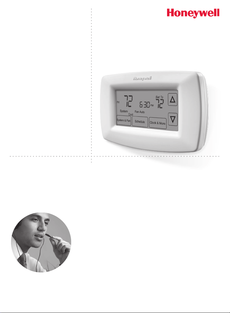
Touchscreen
Programmable
RTH7600
Thermostat
RET97C
Series
Owner’s Manual
Read and save these
instructions.
For help please visit
yourhome.honeywell.com
Installation is Easy
1. Label wires and remove your old thermostat
2. Install and wire your new thermostat
3. Set your new thermostat to match your heating/cooling system
• This thermostat works with virtually all System Types
• It is preset for the most common system
Do you need assistance? We are here to help.
Call 1-800-468-1502 for wiring assistance before returning
the thermostat to the store.
This thermostat works on 24 volt or 750 mV systems.
It will NOT work on 120/240 Volt systems.
Page 2
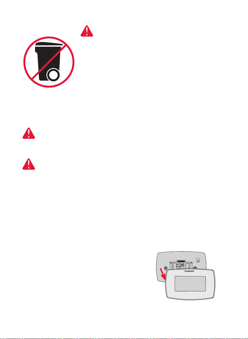
ATTENTION: MERCURY RECYCLING NOTICE
NO MERCUR
MERCURIO
This product does not contain mercury. However,
this product may replace a product that contains
Hg
Y
NO BOTE
This thermostat contains a Lithium battery which may contain
Perchlorate material.
Perchlorate Material—special handling may apply, See www.dtsc.
ca.gov/hazardouswaste/perchlorate
NOTICE: To avoid possible compressor damage, do not run air
conditioner if the outside temperature drops below 50°F (10°C).
mercury. Mercury and products containing
mercury should not be discarded in household
trash.
For more information on how and where to
properly recycle a thermostat containing
mercury in the United States, please refer to the
Thermostat Recycling Corporation at
www.thermostat-recycle.org.
For mercury thermostat recycling in Canada,
please refer to Switch the Stat at
www.switchthestat.ca
Customer assistance
For assistance with this product, please visit
http://yourhome.honeywell.com.
Or call Honeywell Customer Care toll-free at
1-800-468-1502.
To save time, please note your model number
and date code before calling.
Pull at bottom to remove thermostat from
wallplate.
Turn thermostat over to find model number
and date code.
® U.S. Registered Trademark. Patents pending.
US Patent No. 6,595,430; 7,114,554; 7,274,972; 7,225,054 and other patents pending
2
Page 3
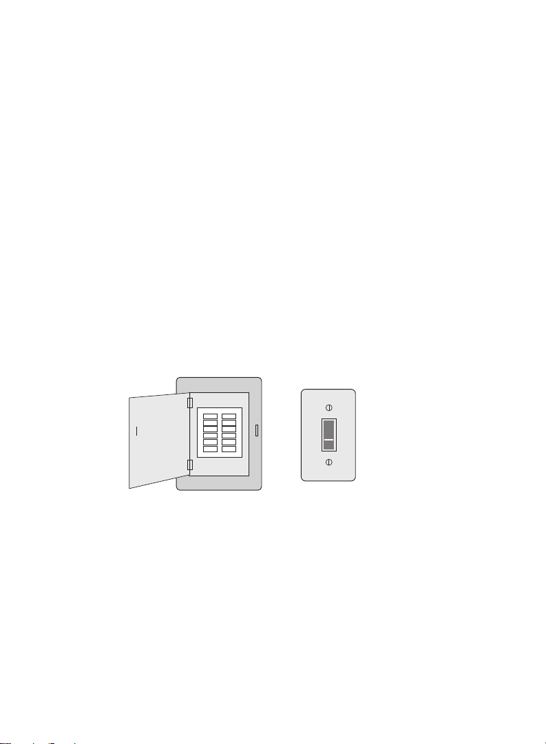
Table of contents
Installation
Installation ............................................3
Advanced Installation .........................10
About your new thermostat
Controls and Home screen
quick reference ...................................13
Preset energy-saving schedules ........14
Programming and operation
Setting the clock .................................14
Adjusting program schedules .............15
Overriding schedules temporarily ......15
Overriding schedules permanently ....16
Auto Changeover ...............................16
Change filter .......................................17
Replace batteries ...............................18
Appendices
Troubleshooting .................................. 19
Limited warranty .................................20
1 Turn Off Power to Heating/Cooling System
or
Circuit breaker
box
Heating/cooling system
power switch
3
Page 4
M28100
2 Remove Old Thermostat
M28073
Remove old thermostat but leave wallplate with wires attached.
If you have an older thermostat with a
Do not remove wallplate yet
sealed mercury tube, turn to page 2
for proper disposal instructions.
Terminal
designation
C
C
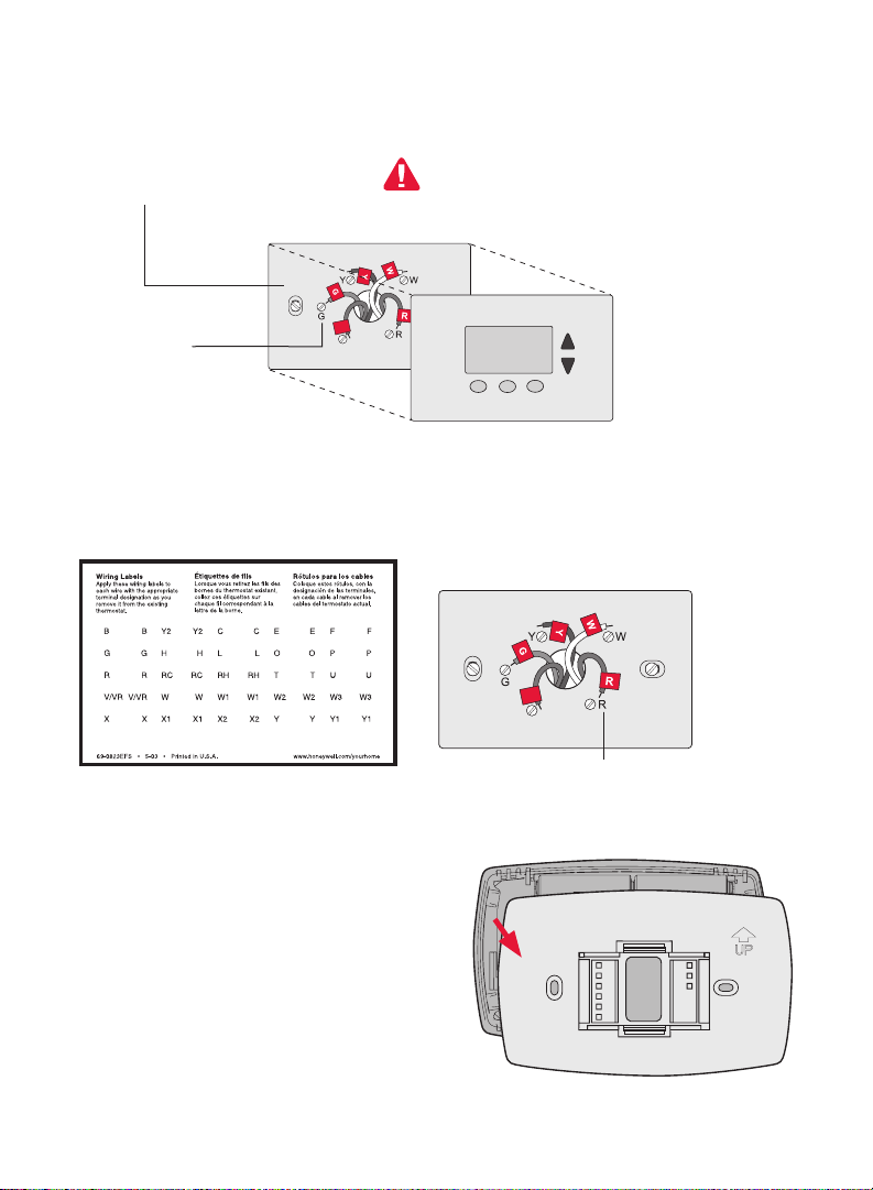
3 Label Wires with Tags
Label the wires using the supplied wire labels as you disconnect them, then
remove the old wallplate. Wire color might not match labels.
Wire Labels
C
C
Terminal designation
4 Separate Wallplate from New Thermostat
Remove wallplate from the new thermostat
and mount onto wall.
Wallplate
4
Page 5
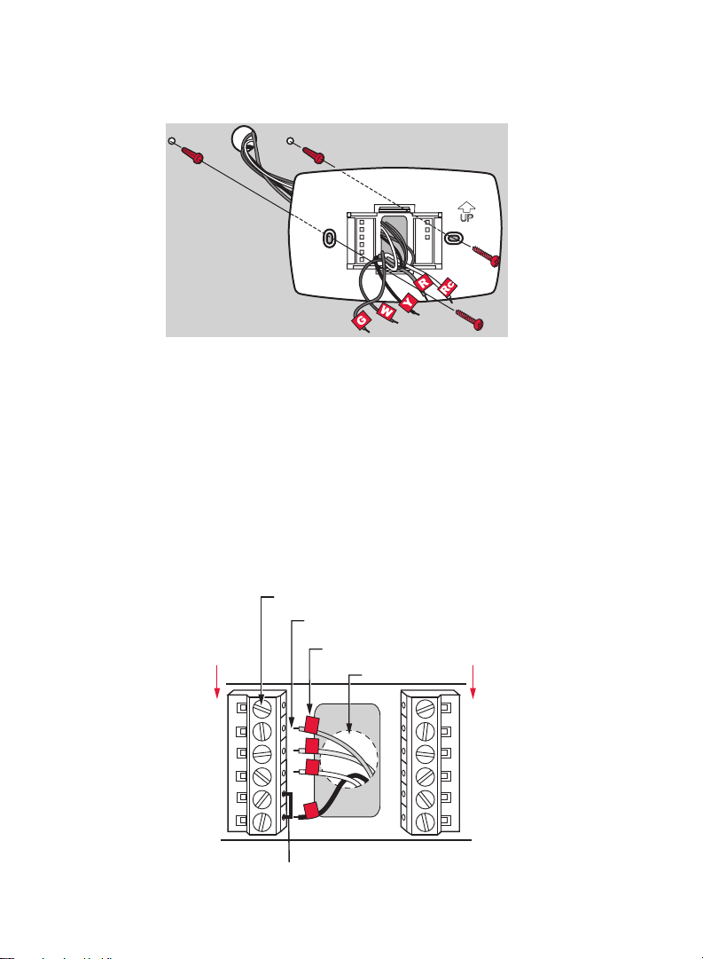
5 Mount Wallplate
Mount the new wallplate using the included screws and anchors.
MCR28094
Drill 3/16-in. holes for drywall
Drill 3/32-in. holes for plaster
6 Connect Wires
Simply match wire labels.
If labels do not match letters on the thermostat, check “Alternate Wiring
(Conventional Systems)” on page 6 and connect to terminal as shown here
(see notes, below).
We are here to help. Call 1-800-468-1502 for wiring assistance.
SCREW
INSERT WIRES
THEN TIGHTEN SCREWS
CONVENTIONAL
LABELED WIRES
WIRE HOLE
CONVENTIONAL
C
G
Y
W
RC
R
G
Y
W
R
Remove metal jumper if you have
both R and Rc wires.
5
W2
Y2
MCR28070
Page 6
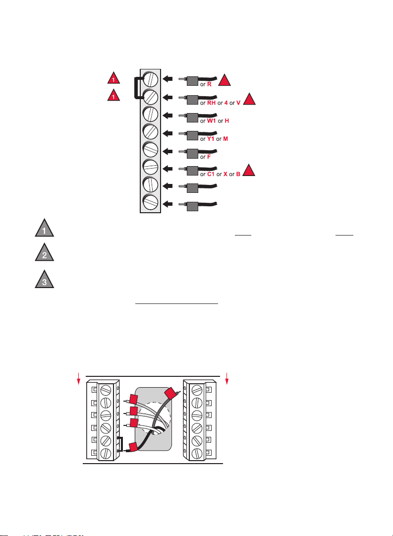
Alternate Wiring (Conventional Systems)
MCR28076
MCR33552
HEAT PUMP
HEAT PUMP
If labels do not match terminals, connect wires as shown here (see notes,
below).
RC
R
W
Y
G
C
Y2
W2
Rc
Y2
W2
2
R
W
Y
G
C
2
3
Remove metal jumper connecting R and Rc only if you must connect both
R and Rc wires.
If your old thermostat had both R and RH wires, remove metal jumper.
Connect the R wire to the Rc terminal, and the RH wire to the R terminal.
If your old thermostat had only 1 C or C1 wire, connect it to the C terminal.
If your old thermostat had 2 C or C1 wires, wrap each separately with
electrical tape and do not connect them.
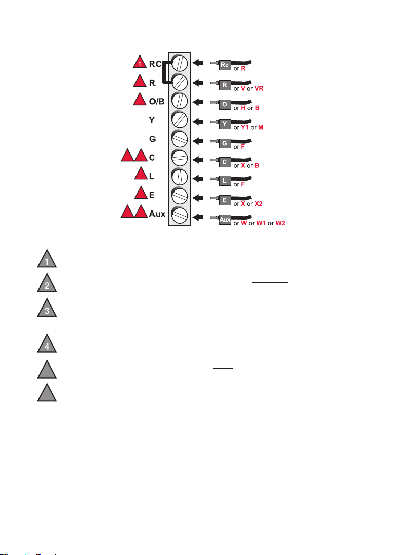
Alternate Wiring (Heat Pump)
If labels do not match letters on thermostat, see page 7.
O/B
RC
C
G
Y
R
G
Y
O
R
Aux
NOTE: If E and Aux
Aux
do not each have a
E
wire connected, use a
L
small piece of wire to
connect them to each
other.
6
Page 7
Alternate Wiring (For Heat Pumps Only)
MCR28077
2
3
3
5
5
6
6
4
Leave metal jumper in place, connecting R & Rc terminals.
If your old thermostat had both
V and VR wires, stop now and contact a
qualified contractor for help.
If your old thermostat had separate
the
C terminal. If another wire is attached to the C terminal, stop now and
O and B wires, attach the B wire to
contact a qualified contractor for help.
If your old thermostat had
Y1, W1 and W2 wires, stop now and contact a
qualified contractor for help.
If
L terminal is used, C terminal wire must be connected (contact a
5
contractor if there is no
If
E and Aux terminals do not each have a wire connected, use a small
6
piece of wire to connect them to each other.
C wire).
7
Page 8
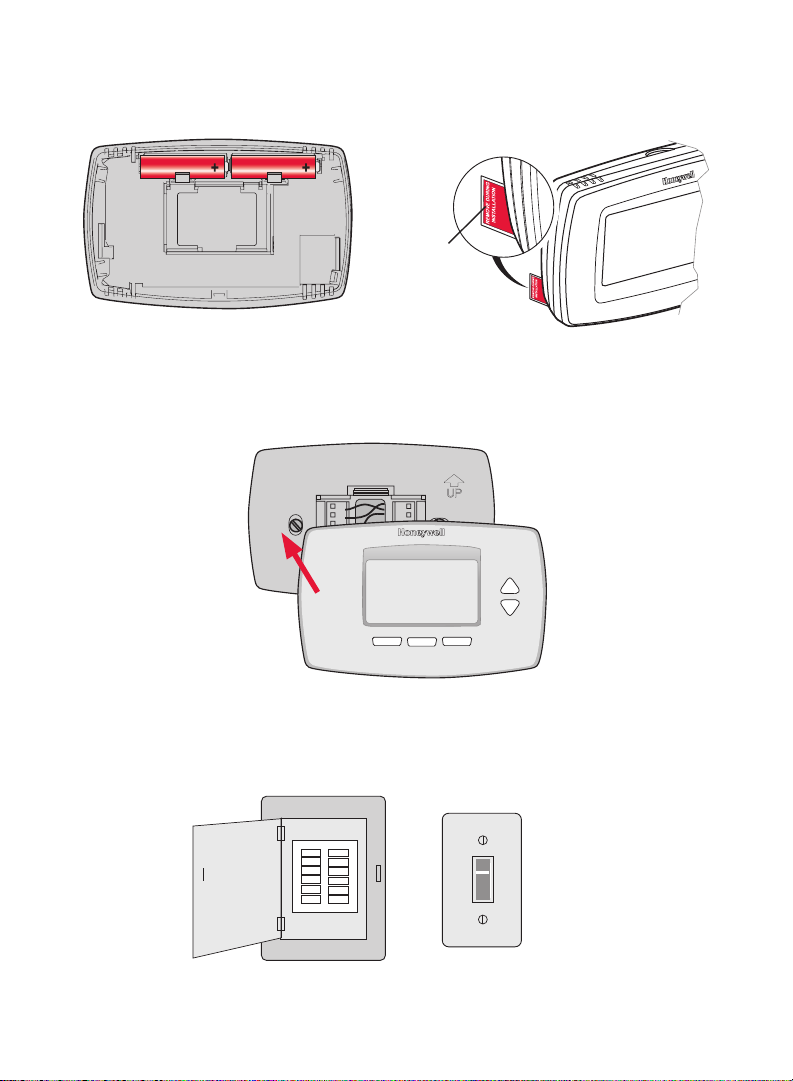
7 Install Batteries
MCR28101
MCR27518
M28103
Install two AA alkaline batteries and remove tab.
Remove tab
Back of thermostat
8 Install Thermostat onto Wallplate
Install thermostat onto the wallplate on the wall.
9 Turn Power Back On
Turn the power back on to the heating/cooling system.
or
Circuit breaker box Heating/cooling system
power switch
8
Page 9
10 Set Time and Date
MCR33548
MCR33549
1. Press s or t to set month, then press NEXT.
2. Press s or t to set day, then press NEXT.
3. Press s or t to set year, then press DONE.
4. Press s or t to set time, then press DONE to save and exit.
6
Go Back
2012
Next
15
Done
10:10
Done
11 If your system type is...
If your system type is:
q Single Stage Heat and Cool
Congratulations, you’re done!
If your system type is:
q Multistage Heat and Cool
q Heat Pump* without Backup Heat
q Heat Pump* with Backup Heat
q Heat Only
q Cool Only
Continue with Advanced Installation on next page to match your thermostat to
your system type.
*Heat Pump—an air conditioner that provides cooling in the summer, and also
runs in reverse in the winter to provide heating.
If you are not sure of your system type or if you have other
questions, call us toll-free at 1-800-468-1502.
This thermostat works on 24 volt or 750 mV systems. It will NOT work on multistage conventional systems.
9
Page 10
Advanced Installation
0
7
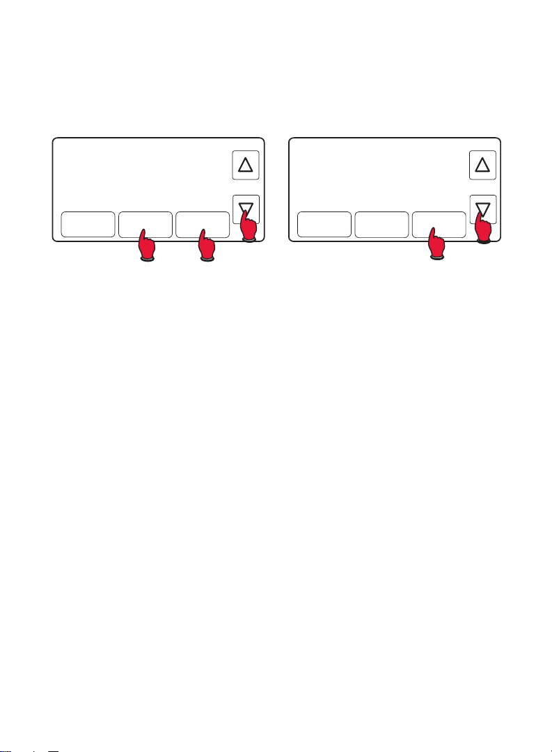
Enter System Setup
1. Press and release the left button.
2. Press and hold the center button until the screen changes (approximately
5 seconds).
Mon
Set To
72
System
System & Fan
Cool
6:30
Fan Auto
Schedule
72
PM
Clock & Mode
MCR3355
System
System
Heat Off Cool
Fan Auto
Fan
Done
MCR3359
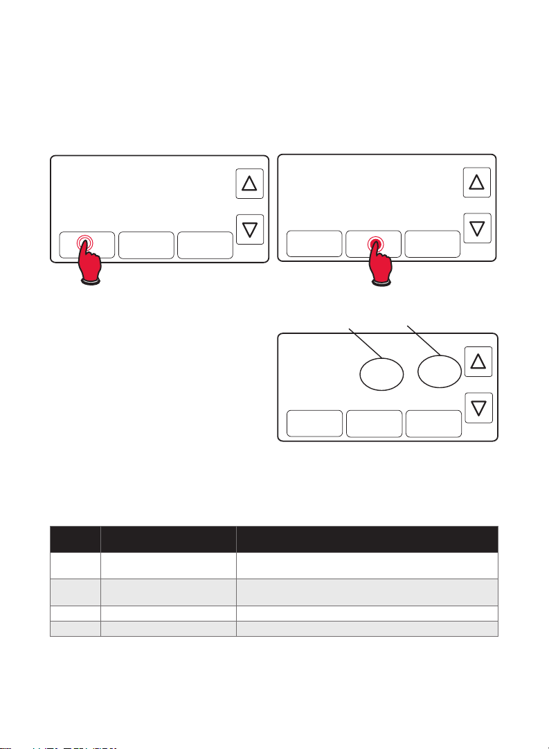
Changing Settings
1. Press the s or t button to change
the setting.
2. Press NEXT to advance to next
function.
3. Press DONE to save & exit.
NOTE: Some functions in the following pages may not appear due to previous
selections made.
Function Description Setting
0120 Year Setting
(first two digits)
0130 Year Setting
(second two digits)
0140 Month Setting 01 - 12 (i.e., January - December)
0150 Date Setting 01 - 31
Press the s or t button to change the setting.
20 = Year 20xx
21 = Year 21xx
01 - 99 (i.e., 2001 - 2099
Function Setting
0120
Go BackNext Done
20
MCR33551
10
Page 11
Function Description Setting
0170 Select System Type 1 Heat/cool: Gas, oil or electric heating with central air
0180 Heating Fan Control 0 Gas or oil heat: Use this setting if you have a gas or oil
0190 Heat Pump Changeover Valve
(for heat pumps only)
0240 Heating Cycle Rate 5 Gas or oil furnace: Standard gas/oil furnace (less than 90%
0270 Emergency Heat Cycle Rate
(heat pumps only)
0300 Manual/Auto Changeover 0 Manual changeover (Heat/Cool/Off).
0320 Temperature Format (°F/°C) 0 Fahrenheit
0330 Daylight Saving Time On/Off 0 Off: No adjustment for daylight saving time.
Press the s or t button to change the setting.
conditioning.
2 Heat pump: Heat pump without backup or auxiliary heat.
3 Heat only: Gas, oil or electric heat without central air
conditioning.
4 Heat only with fan: Gas, oil or electric heat without central air
conditioning.
5 Hot water heat only (no fan): Gas, oil or hot water heat
without central air conditioning.
6 Cool only: Central air conditioning only.
7 Heat pump: Heat pump with backup or auxiliary heating.
8 Heat/Cool Multiple stages: 2 heat stages (wires on W and
W2), 2 cooling stages (wires on Y and Y2).
9 Heat/Cool Multiple stages: 2 heat stages (wires on W and
W2), 1 cooling stage (wire on Y).
10 Heat/Cool Multiple stages: 1 heat stage (wire on W), 2
cooling stages (wires on Y and Y2).
heating system (system controls fan operation).
1 Electric heat: Use this setting if you have an electric heating
system (thermostat controls fan operation).
0 Cooling changeover valve: Use this setting if you connected
a wire labeled “O” to the O/B terminal (see page 6).
1 Heating changeover valve: Use this setting if you connected
a wire labeled “B” to the O/B terminal (see page 7).
efficiency).
9 Electric furnace: Electric heating systems.
3 Heat pump, hot water or high-efficiency furnace: Hot water
system or gas furnace (more than 90% efficiency).
1 Gas/oil steam or gravity system: Steam or gravity heat
systems.
Settings 5, 9, 3, or 1 recommended. Other settings: 2, 4, 6, 7,
8, 10, 11, 12. The number indicates how frequently the system
cycles on and off to maintain the set temperature. A higher
number means the system is on and off for shorter amounts
of time, a lower number means longer on and off times. When
these settings are set to match the system type, the thermostat
controls temperature more accurately.
9 Electric furnace: Electric heating systems.
1 Automatic changeover (Heat/Cool/Auto/Off). Automatically
turns on Heat or Cool based on room temperature. Note:
System maintains minimum 3°F difference between heat and
cool settings.
1 Celsius
1 On: Auto-change to daylight saving time (for areas that do
not use the new 2007 DST calendar).
2 On: Auto-change to daylight saving time (2007 and beyond,
for areas that use the new 2007 DST calendar).
11
Page 12
Function Description Setting
0500 Furnace Filter Change Reminder 0 Off (no reminder)
0530 Smart Response® Technology 1 On
0600 Maximum Heat Setting 90°F (other options: 40-89°F [4-32°C])
0610 Minimum Cool Setting 50°F (other options: 51-99°F [11-37°C])
0640 Clock Format 12 12-hour clock (i.e., “3:30 pm”)
Press the s or t button to change the setting.
1 Reminder in about 1 month
2 Reminder in about 3 months
3 Reminder in about 6 months
4 Reminder in about 9 months
5 Reminder in about 1 year
6 Reminder in about 3 years
0 Off
24 24-hour clock (i.e., “15:30”)
About your new thermostat
Your new Honeywell thermostat has been designed to give you many years of
reliable service and easy-to-use, push-button climate control.
• Large touchscreen display with backlight is easy to read—even in the dark.
• Daily program schedules maximize comfort and economy.
• One-touch temp control overrides program schedule at any time.
• Precise comfort control keeps temperature within 1°F of the level you set.
• Change/check reminder lets you know when to replace furnace filter.
12
Page 13

Thermostat controls
M27526
Mon
75
Recovery
System
Cool
System & Fan
System & Fan
Press to select fan
operation or system.
Fan Auto
Schedule
6:01
AM
Clock & Mode
Set To
75
Heat On
Display screen
temperature
Day of week
Smart
Response®
Technology
in effect (see
page 17)
Mon
75
System
Cool
System & Fan
Recovery
M27525
Arrow keys
Press to adjust temperature or
to make selections from screen
menus.
Clock & More
Press to set clock or furnace filter
reminder.
Schedule
Press to set program schedule (see
pages 14–16).
Temperature settingCurrent timeCurrent inside
System Status
6:01
Fan Auto
Schedule
AM
Clock & Mode
Set To
75
Heat On
Cool On: Cooling system
is on.
Heat On: Heating system
is on.
Aux Heat On: Auxiliary
heating system is activated
(heat pump systems only)
Press the SYSTEM & FAN button, then press…
…SYSTEM to select:
Heat: Heating system control.
Cool: Cooling system control.
Auto: Thermostat automatically selects heating or
cooling depending on the indoor temperature.
Off: All systems off.
Em Heat: Emergency & Auxiliary Heat control.
Compressor is locked out. (Select models only.)
13
…FAN to select:
Auto: Fan runs only when heating
or cooling system is on.
On: Fan runs continuously.
Press DONE to exit and save
settings.
Page 14

Clock setting
M27527
M27528
1. To set the current time display,
press CLOCK & MORE, then press
sor t to adjust the time.
Press and hold sor t to advance
the time more quickly.
2. Press DONE to save & exit (or press
GO BACK to exit without changing
the time).
NOTE: The real-time clock should
never require adjustment since it
automatically updates for daylight
savings time, and stores all date/time
information.
System & Fan
MON
Go Back
Schedule
6:01
Clock & Mode
AM
Done
Program Schedule
You can program four time periods each day, with different settings for
weekdays and weekends. We recommend the pre-set settings (shown in the
table below), since they can reduce your heating/cooling expenses.
Wake - Set to the time you
awaken and the temperature you
want during the morning, until
you leave for the day.
Leave - Set to the time you leave
home and the temperature you
want while you are away (usually
an energy-saving level).
Return - Set to the time you
return home and the temperature
you want during the evening,
until bedtime.
Sleep - Set to the time you go to bed and the temperature you want overnight
(usually an energy-saving level).
NOTE: Leave and Return periods can be canceled on weekends.
Wake
(6:00 am)
Leave
(8:00 am)
Return
(6:00 pm)
Sleep
(10:00 pm)
Heat Cool
°
70
62
70
62
°
°
°
75
83
75
78
°
°
°
°
14
Page 15

To adjust program schedules
M27527
M27530
M27531
M27532
1. Press SCHEDULE, then EDIT to see
weekdays.
System & Fan
2. Press SELECT DAY to highlight Mon-Fri
(they will share the same settings).
3. Press NEXT STEP twice, then press s or
t to set Wake time for selected days.
Go Back
4. Press NEXT STEP, then s or t to set
Heat temperature for this time period.
5. Press NEXT STEP, then s or t to set
Cool temperature for this time period.
6. Repeat steps 3-5 to program other
time periods (LEAVE, RETURN, SLEEP),
then press DONE.
7. Repeat steps 1-6 to program
MON
TUE
WED
THU
FRI
Go Back
Saturday/Sunday. (Press s or t until
the desired day is flashing, then press
SELECT DAY.)
8. Press DONE to save & exit.
Program schedule override (temporary)
Press s or t to immediately adjust
the temperature. This will temporarily
override the temperature setting for
the current time period.
The new temperature will be
maintained until the next time period.
When the timer expires, the program
schedule will resume and set the
temperature to the level you’ve
programmed for the current time
period.
To cancel the temporary setting at
any time, press USE SCHEDULE.
Mon
62
System
Heat
System & Fan
Fan Auto
Schedule
Schedule
Edit
Period
Wake
6:00
Next Step
6:08
Use
Clock & Mode
AM
Temporary
AM
68
Heat On
Clock & Mode
Done
Set To
View
Set To
62
Heat
15
Page 16

Program schedule override (permanent)
M27534
M27533
Press s or t to adjust temperature,
then press HOLD. This will turn off the
program schedule.
Whatever temperature you set will
be maintained 24 hours a day, until
you manually change it, or press
USE SCHEDULE to cancel “Hold” and
Mon
System
Heat
62
6:08
Fan Auto
Hold
Temporary
Set To
AM
68
Permanent Hold
Cancel
resume the program schedule.
Auto changeover
Use this feature in climates where both air conditioning and heating are
used on the same day. When the system mode is in Auto, the thermostat
automatically selects heating or cooling depending on the indoor temperature.
While in the Auto mode, if a schedule override takes place (temporarily or
permanently) the thermostat will automatically adjust the cooling and heating
settings to maintain a 3-degree separation between the cool and heat settings.
For example, if the heat temperature
is raised to where it gets within
3-degrees of the cool setting, the
display will show an up arrow next
to “Cool” to show the thermostat is
raising the cool setting up to maintain
a 3-degree separation.
The display will also show both “Auto”
and either “Heat” or “Cool” for which
temperature setting you are currently
adjusting. Press the system button to select between the heat and cool to view/
adjust either mode.
Tue
69
System Auto
Heat
System
º
Fan Auto
1:09
Hold
PM
Cancel
Temporary
Set To
74
Heat
Cool
CAUTION: To avoid possible compressor damage, do not use Auto
Changeover if the outside temperature drops below 50°F (10°C).
16
Page 17

Filter reminder
M27535
M27536
If activated during installation, the
furnace filter reminder alerts you
Change Filter
Set To
when it is time to replace your
AM
filter.
Press RESET after changing the
filter, to restart the timer.
To reset the reminder interval
System
70
Reset
Heat
6:01
Fan Auto
Schedule
70
Heat On
Clock & Mode
before it expires:
1. Press MORE, then NEXT.
2. Press RESET.
3. Press DONE to save and exit.
Reset
Next
60
Days
Done
Special features
Smart Response® Technology: This feature allows the thermostat to
“learn” how long the furnace and air conditioner take to reach programmed
temperature settings, so the temperature is reached at the time you set. For
example: Set the Wake time to 6 am, and the temperature to 70°. The heat will
come on before 6 am, so the temperature is 70° by the time you wake at 6.
The message “Recovery” is displayed when the system is activated before a
scheduled time period.
Compressor Protection: This feature forces the compressor to wait a few
minutes before restarting, to prevent equipment damage. During the wait time,
the message “Wait” is displayed on screen.
Auto Changeover: This feature is used in climates where both air conditioning
and heating are used on the same day. When the system is set to Auto,
the thermostat automatically selects heating or cooling depending on the
indoor temperature. Heat and cool settings must be at least 3 degrees apart.
The thermostat will automatically adjust settings to maintain this 3-degree
separation.
17
Page 18

Battery replacement
Batteries are optional (to provide
backup power) if your thermostat
was wired to run on AC power when
installed.
Install fresh batteries immediately when
the LO BATT warning begins flashing.
The warning flashes about 30 days
before batteries are depleted.
Even if the warning does not appear,
you should replace batteries once a
year, or before leaving home for more
than a month.
Grasp thermostat and pull to
remove from wallplate
Turn thermostat over, insert
fresh AA alkaline batteries,
then reinstall thermostat.
18
Page 19

Troubleshooting
If you have difficulty with your thermostat, please try the following suggestions.
Most problems can be corrected quickly and easily.
Display is blank • Check circuit breaker and reset if necessary.
• Make sure power switch at heating & cooling system is on.
• Make sure furnace door is closed securely.
• Make sure fresh AA alkaline batteries are correctly installed.
Temperature
settings do not
change
Heating or
cooling system
does not respond
Make sure heating and cooling temperatures are set to acceptable
ranges:
• Heat: 40° to 90 °F (4.5° to 32 °C).
• Cool: 50° to 99 °F (10° to 37 °C).
• Press SYSTEM to set system to Heat. Make sure the temperature
is set higher than the Inside temperature.
• Press SYSTEM to set system to Cool. Make sure the temperature
is set lower than the Inside temperature.
• Check circuit breaker and reset if necessary.
• Make sure power switch at heating & cooling system is on.
• Make sure furnace door is closed securely.
• Wait 5 minutes for the system to respond.
Cannot change
system setting
• Check Function 0170: System Type to make sure it is set to
match your heating and cooling equipment.
to Cool
Fan does not
turn on when
• Check Function 0180: Heating Fan Control to make sure it is set
to match your heating equipment.
heat is required
Heating system
is running in cool
• Check Function 0170: System Type to make sure it is set to
match your heating and cooling equipment.
mode
Red light is on • If thermostat is in Emergency Heat mode the red light is normal.
It shows that the thermostat is in emergency heat mode.
• If thermostat is not in Emergency Heat mode, contact a qualified
service contractor for repair.
“Wait” appears
on the screen
• Compressor protection feature is engaged. Wait 5 minutes for the
system to restart safely, without damage to the compressor.
Heat pump
issues cool air
• Check Function 0190: Heat Pump Changeover Valve to make
sure it is properly configured for your system.
in heat mode, or
warm air in cool
mode
For assistance with this product, please visit http://yourhome.honeywell.com or
call Honeywell Customer Care toll-free at 1-800-468-1502.
19
Page 20

33-00089ES-01
1-year limited warranty
Honeywell warrants this product, excluding battery, to be free from defects in the
workmanship or materials, under normal use and service, for a period of one (1) year
from the date of purchase by the consumer. If at any time during the warranty period the
product is determined to be defective or malfunctions, Honeywell shall repair or replace it
(at Honeywell’s option).
If the product is defective,
(i) return it, with a bill of sale or other dated proof of purchase, to the place from which
you purchased it; or
(ii) call Honeywell Customer Care at 1-800-468-1502. Customer Care will make the
determination whether the product should be returned to the following address:
Honeywell Return Goods, Dock 4 MN10-3860, 1885 Douglas Dr. N., Golden Valley, MN
55422, or whether a replacement product can be sent to you.
This warranty does not cover removal or reinstallation costs. This warranty shall not apply
if it is shown by Honeywell that the defect or malfunction was caused by damage which
occurred while the product was in the possession of a consumer.
Honeywell’s sole responsibility shall be to repair or replace the product within the terms
stated above. HONEYWELL SHALL NOT BE LIABLE FOR ANY LOSS OR DAMAGE
OF ANY KIND, INCLUDING ANY INCIDENTAL OR CONSEQUENTIAL DAMAGES
RESULTING, DIRECTLY OR INDIRECTLY, FROM ANY BREACH OF ANY WARRANTY,
EXPRESS OR IMPLIED, OR ANY OTHER FAILURE OF THIS PRODUCT. Some states
do not allow the exclusion or limitation of incidental or consequential damages, so this
limitation may not apply to you.
THIS WARRANTY IS THE ONLY EXPRESS WARRANTY HONEYWELL MAKES ON
THIS PRODUCT. THE DURATION OF ANY IMPLIED WARRANTIES, INCLUDING THE
WARRANTIES OF MERCHANTABILITY AND FITNESS FOR A PARTICULAR PURPOSE, IS
HEREBY LIMITED TO THE ONE-YEAR DURATION OF THIS WARRANTY.
Some states do not allow limitations on how long an implied warranty lasts, so the above
limitation may not apply to you. This warranty gives you specific legal rights, and you may
have other rights which vary from state to state.
If you have any questions concerning this warranty, please write Honeywell Customer
Relations, 1985 Douglas Dr, Golden Valley, MN 55422 or call 1-800-468-1502.
Automation and Control Solutions
Honeywell International Inc.
1985 Douglas Drive North
Golden Valley, MN 55422
yourhome.honeywell.com
® U.S. Registered Trademark.
© 2015 Honeywell International Inc.
33- 00 089ES—01 M.S. 07-15
Printed in U.S.A.
Page 21

Termostato
RTH7600
Programable
RET97C
Series
Manual del
propietario
Lea y guarde estas
instrucciones.
Para obtener ayuda, visite
yourhome.honeywell.com
La instalación es fácil
1. Rotule los cabes y retire el termostato viejo
2. Instale y conecte los cables de su nuevo termostato
3. Ajuste su nuevo termostato para que concuerde con su sistema de calefacción/
refrigeración
• Este termostato funciona prácticamente con todos los tipos de sistemas
• Está preconfigurado para el sistema más común
¿Necesita ayuda? ¡Aquí estamos!
Llame al 1-800-468-1502 para obtener asistencia con el
cableado antes de devolver el termostato a la tienda.
Este termostato funciona con sistemas de 24 voltios o
750 mV. NO funciona con sistemas de 120/240 voltios.
Page 22

ATENCIÓN: AVISO PARA EL RECICLAJE DEL
NO MERCUR
MERCURIO
MERCURIO
Este producto no contiene mercurio. Sin
Hg
Y
NO BOTE
Este termostato tiene una batería de litio que puede contener perclorato.
Perclorato: puede ser necesario manipularlo con métodos especiales.
Visite www.dtsc.ca.gov/hazardouswaste/perchlorate
AVISO: Para evitar posibles daños al compresor, no utilice el aire
acondicionado si la temperatura externa es inferior a 50 °F (10 °C).
embargo, este producto puede reemplazar
uno que contenga mercurio. El mercurio y los
productos que contengan mercurio no se deben
desechar con los desperdicios domésticos.
Para más información sobre cómo y dónde
reciclar adecuadamente un termostato que
contenga mercurio en los Estados Unidos,
consulte con Thermostat Recycling Corporation
en www.thermostat-recycle.org.
Para el reciclaje de termostatos con mercurio en
Canadá, consulte con Switch the Stat en
www.switchthestat.ca
Asistencia al cliente
Para obtener asistencia relacionada con este
producto, visite http://yourhome.honeywell.com.
O comuníquese con el número gratuito del servicio de
atención al cliente, llamando al 1-800-468-1502.
Para ahorrar tiempo, anote el número de modelo y el
código de fecha antes de llamar.
Gire el termostato para ver el número de
modelo y el código de fecha.
® Marca registrada en EE.UU. Patentes pendientes.
Patente en EE.UU: Nº 6,595,430; 7,114,554; 7,274,972; 7,225,054 y otras patentes pendientes
2
Page 23

Acerca
Instalación
Instalación ............................................3
Guía de instalación avanzada ............10
Acerca de su nuevo termostato
Referencia rápida de los controles
y la pantalla de inicio .........................13
Cronogramas de ahorro de
energía predeterminados ................... 14
Programación y funcionamiento
Configuración del reloj .......................14
Ajuste de los cronogramas
del programa ......................................15
Anulación temporal de
los cronogramas.................................15
Anulación permanente
de los cronogramas ...........................16
Conversión automática ......................16
Cambio del filtro .................................17
Reemplazo de la batería ....................18
Apéndices
Localización y solución
de problemas .....................................19
Garantía limitada ................................20
1 Desconecte la alimentación en el sistema de
calefacción/refrigeración
o
Caja de interruptores
de circuito
Interruptor de energía del sistema
de calefacción/refrigeración
3
Page 24

M28100
2 Remueva su viejo termostato
M28073
Retire el termostato existente pero deje la placa de montaje con los cables
adheridos.
No retirar la placa
mural todavía
Si el termostato existente tiene un tubo de mercurio
sellado, vaya a la página 2 para obtener instrucciones
sobre cómo desecharlo adecuadamente.
Designación de
los terminales
C
C
3 Identifique los cables
Identifique los cables a medida que los desconecta, utilizando las etiquetas
que se suministran. Seguidamente retire la placa de pared existente. Es
posible que el color del cable no coincida con las etiquetas.
Rótulos para los cables
C
C
Designación de los terminales
4 Separe la placa de montaje del termostato nuevo
Retire la placa de montaje del termostato
nuevo y móntela en la pared.
Placa de montaje
4
Page 25

5 Coloque la placa de montaje
MSCR28070
TORNILLO
Monte la nueva placa de montaje utilizando los tornillos y anclajes que se
suministran.
MCR28094
Taladre agujeros de 3/32 in. (2,4 mm) en yeso
Taladre agujeros de 3/16 in. (4,8 mm) en paneles de yeso
6 Conecte los cables
Simplemente haga corresponder las etiquetas de los cables.
Si las etiquetas no corresponden con las letras del termostato, revise “Conexión
alternativa (sistemas convencionales)” en la página 6 y conecte al terminal
como se indica (refiérase a las notas que siguen).
El termostato no trabaja con bombas de calor con calor auxiliar/de reserva.
Estamos aquí para ayudarle. Llame al 1-800-468-1502 para asistencia con el
cableado.
INSERTE LOS CABLES Y
APRIETE LOS TORNILLOS
CONVENCIONAL
C
G
Y
W
RC
R
CABLES ETIQUETADOS
ORIFICIO DE
CABLEADO
G
Y
W
R
CONVENCIONAL
W2
Y2
Retire el empalme metálico si tiene los cables “R” y “Rc”.
5
Page 26

Conexión alternativa (sistemas convencionales)
MSCR28076
MSCR33552
BOMBA DE CALOR
BOMBA DE CALOR
Si las etiquetas no corresponden con los terminales, conecte los cables como
se ilustra aquí (ver notas más abajo).
RC
R
W
Y
G
C
Y2
W2
Rc
Y2
W2
2
R
W
Y
G
C
2
3
Quite el empalme metálico que conecta R y RC solamente si usted debe
conectar los alambres de R y de Rc.
Si su viejo termóstato tenía R y RC los alambres, quite el empalme.
Conecte el alambre de R con el terminal de Rc, y el alambre Rc con el
terminal de R.
Si su viejo termóstato tenía solamente 1 alambre C o C1, conéctelo con
el terminal de C. Si su viejo termóstato tenía 2 alambres C o C1, envuelva
cada uno con la cinta eléctrica y no los conecte.
Conexión alternativa (bomba de calor)
Si los rótulos no coinciden con las letras de los terminales en el termostato,
consulte la página 7.
O/B
RC
C
G
Y
G
Y
O
Aux
Aux
E
L
NOTE: Si E y Aux
no tienen un cable
conectado cada uno,
utilice una pequeña
pieza de cable para
R
R
6
conectarlos uno con
otro.
Page 27

Conexión alternativa (pour thermopompes seulement)
MSCR28077
2
3
3
5
5
6
6
4
Deje el empalme en lugar, entre terminales de R y Rc.
Si su viejo termóstato tenía alambres V y VR, ahora pare y entre en
contacto con un contratista para la ayuda.
Si su viejo termóstato tenía alambres separados de O y de B, una el
alambre de B al terminal de C. Si otro alambre se une al terminal de C,
ahora pare y entre en contacto con un contratista para la ayuda.
Si su viejo termóstato tenía alambres Y1, W1 y W2, ahora pare y entre en
contacto con un contratista para la ayuda.
Si se utiliza L terminal, el alambre terminal de C debe ser conectado
5
(entre en contacto con un contratista si no hay alambre de C).
Si E y los terminales Aux cada uno no tienen un alambre conectado,
6
utilice un pedazo pequeño de alambre para conectarlos el uno al otro.
7
Page 28

7 Instale las baterías
MCR28101
MCR27518
M28103
Instale dos baterías alcalinas AA en la parte de atrás del termostato.
Retire la
lengüeta.
Parte de atrás del termostato
8 Instale el termostato en la placa de montaje
Instale el termostato en la placa de montaje en la pared.
9 Active nuevamente el suministro eléctrico
Active nuevamente el suministro eléctrico del sistema de calefacción/aire
acondicionado.
o
Caja de interruptores
de circuito
Interruptor de energía del sistema
de calefacción/refrigeración
8
Page 29

10 Ajuste de fecha y hora
MCR33548
MCR33549
1. Oprima s o t para ajustar el mes, después oprima NEXT.
2. Oprima s o t para ajustar la fecha, después oprima NEXT.
3. Oprima s o t para ajustar el año, después oprima DONE.
4. Oprima s o t para ajustar la hora, después oprima DONE para salir y
guardar los ajustes.
6
Go Back
2012
Next
15
Done
10:10
Done
11 Si su tipo de sistema es...
Si su tipo de sistema es:
q Calor y frío de una sola etapa
¡Felicitaciones, ya está listo!
Si su tipo de sistema es:
q Calor y frío de etapas múltiples
q Bomba de calor* sin calor de respaldo
q Bomba de calor* con calor de respaldo
q Solo calor
q Solo frío
Continúe con la instalación avanzada para adaptar el termostato a su tipo de
sistema.
*Bomba de calor—un acondicionador de aire que proporciona enfriamiento en
el verano y también funciona en reversa en el invierno, proporcionando calor.
Si no está seguro del tipo de sistema que tiene o si tiene otras
preguntas, llámenos gratis al 1-800-468-1502.
Este termostato funciona con sistemas de 24 voltios o 750 mV. NO funciona
con sistemas de 120/240 voltios.
9
Page 30

Guía de instalación avanzada
0
7
Ingrese la configuración del sistema
1. Presione y sostenga el botón izquierdo.
2. Presione y sostenga el botón central hasta que cambie la pantalla
(aproximadamente 5 segundos).
Mon
72
System
System & Fan
Cool
6:30
Fan Auto
Schedule
PM
Clock & Mode
Set To
72
MCR3355
System
System
Heat Off Cool
Fan Auto
Fan
Done
MCR3359
Cómo cambiar la configuración
1. Oprima s o t para cambiar los
ajustes.
2. Oprima NEXT para seleccionar la
función.
3. Oprima DONE para salir y guardar
los ajustes.
NO TA : Algunas funciones de las páginas siguientes puede que no aparezcan
debido a las selecciones efectuadas previamente.
Función Descripción Configuración
0120 Ajuste de año (primeros
dos dígitos)
0130 Ajuste de año (segundos
dos dígitos)
0140 Ajuste de mes
0150 Ajuste de fecha 01 - 31
Oprima s o t para cambiar los ajustes.
20 = Año 20xx
21 = Año 21xx
01 - 99 (ej., 2001 - 2099)
01 - 12 (i.e., Janvier-Décembre)
Función Configuración
0120
Go BackNext Done
20
MCR33551
10
Page 31

Función Descripción Configuración
0170 Seleccione el tipo del
sistema
0180 Control del ventilador de
calefacción
0190 Válvula de cambio (para
bomba de calefacción
solamente)
0240 Frecuencia del ciclo de
calefacción
0270 Calefacción de la
emergencia (para
bomba de calefacción
solamente)
0300 Cambio manual o auto
(RTH7500 solamente)
Oprima s o t para cambiar los ajustes.
1 Calefacción a gas, petróleo o eléctrica con aire acondicionado
central
2 Bombeo de calor (sin calefacción auxiliar)
3 Sólo calefacción (gas, petróleo o eléctrica) sin aire acondicionado
central
4 Sólo calefacción (gas, petróleo o eléctricacon) con el ventilador
5 Calefacción de la agua caliente (o gas/petróleo) sin aire
acondicionado central
6 Sólo refrigeración
7 Bomba de calefacción (con calefacción auxiliar)
8 Sistema múltiple de la etapa: 2 etapas calefacción (alambres en
W y W2), 2 etapas refrigeración (alambres en Y y Y2)
9 Sistema múltiple de la etapa: 2 etapas calefacción (alambres en
W y W2), 1 etapa refrigeración (alambre en Y)
10 Sistema múltiple de la etapa: 1 etapas calefacción (alambres en
W), 2 etapas refrigeración (alambres en Y y Y2)
0 Calefacción a gas/petróleo: (Operación del ventilador de los
controles de sistema).
1 Calefacción eléctrica: (El termóstato controla la operación del
ventilador).
0 Válvula del cambio que se refrigeración: Utilice este ajuste si
usted conectó un alambre etiquetado “O” con el terminal de O/B
(ver página 6).
1 Válvula del cambio que se calefacción: Utilice este ajuste si usted
conectó un alambre etiquetado “B” con el terminal de O/B (ver
página 7).
5 Estufa normal a gas o petróleo que tiene una eficiencia menor al
90%
9 Estufa eléctrica (sistema de calefacción eléctrico)
3 Bomba de calor, sistema de agua caliente o una estufa a gas con
una eficiencia mayor al 90%
1 Sistema vapor (gas o petróleo) o sistema gravedad
Se recomiendan las configuraciones 5, 9, 3 o 1. Otras
configuraciones: 2, 4, 6, 7, 8, 10, 11, 12. El número indica la
frecuencia de ciclos de encendido y apagado del sistema para
mantener la temperatura configurada. Un número más alto significa
que el sistema está encendido o apagado por menor cantidad de
tiempo, un número más bajo significa tiempos de encendido o
apagado más largos. Cuando estas configuraciones se establecen
para que correspondan con el tipo de sistema, el termostato
controla la temperatura de forma más precisa.
9 Estufa eléctrica (sistema de calefacción eléctrico)
0 El cambio manual (Heat/Cool/Off).
1 El cambio automático (Heat/Cool/Auto/Off). Nota: El sistema
mantiene la diferencia mínima 3°F entre el calor y los ajustes
frescos.
11
Page 32

Función Descripción Configuración
0320 Format de la température
(° F/° C)
0330 Ahorro diurno 0 El horario de ahorro de energía diurno está desactivado
0500 Recordatorio de cambio
del filtro de la estufa
0530 Smart Response®
Technology (activo o
apagado)
0600 Máxima de temperatura 90°F (otras opciones: 40 a 89°F [4 a 32°C])
0610 Mínima de enfriamiento 50°F (otras opciones: 51 a 99°F [11 a 37°C])
0640 Formato del reloj 12 Reloj 12-hour (3:30 pm)
Oprima s o t para cambiar los ajustes.
0 Fahrenheit
1 Celsius
1 Cambio automático a horario de ahorro de energía diurno (2006 y
para áreas que no usan el nuevo calendario 2007 DST)
2 Cambio automático a horario de ahorro de energía diurno (2007 y
posterior para áreas que usan el nuevo calendario 2007 DST)
0 Apagado
1 Tiempo de funcionamiento de 1 mes
2 Tiempo de funcionamiento de 3 meses
3 Tiempo de funcionamiento de 6 meses
4 Tiempo de funcionamiento de 9 meses
5 Tiempo de funcionamiento de 1 año
6 Tiempo de funcionamiento de 3 años
1 Activo
0 Apagado
24 Reloj 24-hour (15:30)
Acerca de su nuevo termostato
Su nuevo termostato ha sido diseñado para brindarle muchos años de
funcionamiento confiable y para brindarle un control climático fácil de usar y
con sólo apretar un botón.
• La pantalla grande sensible al tacto con iluminación posterior es fácil de
leer, incluso en la oscuridad.
• Horario diarios del programa para una máxima comodidad y economía.
• El control de temp. de un sólo toque anula el horario programado en
cualquier momento.
• Preciso control de comodidad que mantiene la temperatura dentro del rango
de 1º F del nivel que usted fije.
• Recordatorios para cambiar/controlar le avisan cuándo substituir el filtro de
la estufa.
12
Page 33

Controles del termostato
M27526
Ajuste de la temperatura
Mon
75
System
Cool
System & Fan
Recovery
Fan Auto
Schedule
6:01
AM
Clock & Mode
Set To
75
Heat On
Oprima para ajustar la temperatura,
o para hacer selecciones de
menús.
Clock & More
M27525
System & Fan
Oprima para seleccionar
el funcionamiento del
ventilador o sistema
Oprima para ajustar el reloj o
recordatorio de cambio de filtro de la
estufa.
Schedule
Oprima para anular el horario de
programa (ver páginas 14–16).
Pantalla de visualización
interior actual
Día de la
semana
Smart
Response®
Technology
activado (ver
página 17)
Presione el botón SYSTEM & FAN, luego presione…
… el botón SYSTEM para seleccionar:
Heat: Controla el sistema de calefacción.
Cool: Controla el sistema de refrigeración.
Auto: termostato elige automáticamente cuándo
calentar o enfriar, dependiendo de la temperatura
interior.
Off: Apaga todos los sistemas.
Em Heat: Controla el calor de emergencia y
auxiliar. El compresor se bloquea. (Solamente en
los modelos superiores.)
Mon
75
System
Cool
System & Fan
Recovery
6:01
Fan Auto
Schedule
AM
Clock & Mode
Set To
75
Heat On
… el botón FAN para seleccionar:
Auto: El ventilador funciona solamente
cuando la calefacción o el sistema de
refrigeración están encendidos.
On: El ventilador funciona sin
interrupción.
Presione DONE para salir y guardar la
configuración.
Ajuste de temperaturaHora actualTemperatura
Estado del sistema
Cool On: El sistema
de refrigeración está
encendido.
Heat On: El sistema
de calefacción está
encendido.
Aux Heat On: El sistema
de calefacción auxiliar
está activado (bombas de
calefacción solamente)
13
Page 34

Configuración de la hora y el día
M27527
M27528
1. Para ajustar la hora actual en
pantalla, oprima CLOCK, luego
oprima s o t para ajustar la hora.
Mantenga oprimido s o t para
avanzar la hora con más rapidez.
2. Oprima DONE para guardar y salir
(u oprima GO BACK para salir sin
cambiar la hora).
NO TA : El reloj de hora-real no debería
requerir ajuste nunca ya que se
actualiza automáticamente de acuerdo
al horario de ahorro de energía diurno,
y guarda toda la información de fecha/
hora.
System & Fan
MON
Go Back
Schedule
6:01
Clock & Mode
AM
Done
Cronograma del programa
Puede programar cuatro períodos de tiempo por día, con diferentes
configuraciones para los días de semana y los fines de semana.
Recomendamos estas configuraciones preestablecidas (se muestran en el
cuadro a continuación), debido a que reducen los gastos de calefacción y
refrigeración.
“WAKE” - Programe la hora en
que se despierta y la temperatura
que quiere durante la mañana,
hasta que usted se va de su casa.
“LEAVE” - Programe la hora en
que usted se va de su casa y la
temperatura que quiere mientras
no esté en su casa (por lo general,
un nivel de ahorro de energía).
“RETURN” - Programe la hora
en que regresa a su casa y la
temperatura que quiere durante la
tarde hasta que se va a dormir.
“SLEEP” - Programe la hora en que usted se va a dormir y la temperatura que quiere
durante toda la noche (por lo general, un nivel de ahorro de energía).
NOTA: Los períodos de Leave (Salir) y Return (Regresar) se pueden cancelar en los
fines de semana.
“Wake”
(6:00 a. m.)
“Leave”
(8:00 a. m.)
“Return”
(6:00 a. m.)
“Sleep”
(10:00 a. m.)
14
“Heat” “Cool”
°
70
62
70
62
°
°
°
75
83
75
78
°
°
°
°
Page 35

Para ajustar los horarios de programas
M27527
M27530
M27531
M27532
1. Oprima SCHEDULE, luego oprima EDIT.
2. Oprima SELECT DAY para seleccionar
System & Fan
Schedule
Clock & Mode
Lun-Vier (compartirán los mismos
ajustes).
3. Oprima NEXT STEP dos veces, luego
Go Back
Edit
View
oprima s o t para fijar la hora Wake.
4. Oprima NEXT STEP, luego oprima s
o t para fijar la temperatura Heat
para este período.
5. Oprima NEXT STEP, luego oprima s
o t para fijar la temperatura Cool
para este período.
6. Repita los pasos 3-5 para programar
otros períodos (LEAVE, RETURN,
MON
TUE
WED
THU
FRI
Go Back
Period
Wake
6:00
Next Step
Set To
AM
62
Heat
Done
SLEEP), luego oprima DONE.
7. Repita los pasos 1-6 para programar
Sab-Dom. (Oprima s o t hasta que
está destellando el día deseado, después oprima SELECT DAY.)
8. Oprima DONE para guardar y salir.
Programación de la anulación del cronograma (temporal)
Oprima s o t para ajustar
inmediatamente la temperatura. Esto
anulará temporariamente el ajuste
de temperatura para el período
actual.
La nueva temperatura se mantendrá
hasta la hora que haya fijado.
Cuando se cumpla el plazo, el
horario de programa reanudará y
ajustará la temperatura al nivel que
haya programado para el período
actual.
Para cancelar los ajustes
temporarios en cualquier momento,
oprima USE SCHEDULE.
Mon
62
System
Heat
System & Fan
6:08
Fan Auto
Use
Schedule
Temporary
Set To
AM
68
Heat On
Clock & Mode
15
Page 36

Programación de la anulación del cronograma (permanente)
M27534
M27533
Oprima s o t para ajustar
temperatura, luego oprima HOLD.
Esto apagará el horario de
programas.
Cualquier temperatura que fije se
mantendrá 24 horas al día, hasta
que la cambie manualmente, u
Mon
System
Heat
62
6:08
Fan Auto
Hold
Temporary
Set To
AM
68
Permanent Hold
Cancel
oprima USE SCHEDULE para cancelar
“Hold” y reanude el horario de
programas.
Conversión automática
Utilice esta característica en climas donde se utilicen tanto el aire
acondicionado como la calefacción durante el mismo día. Cuando el sistema
está configurado en Auto (automático), el termostato elige automáticamente
cuándo calentar o enfriar, dependiendo de la temperatura interior.
Mientras está en la modalidad Auto (automático), si ocurre una anulación del
cronograma (temporal o permanente) el termostato ajustará automáticamente
las configuraciones de frío y calor
para mantener una separación de 3
grados entre ellas.
Por ejemplo, si la temperatura de
calefacción se eleva a un punto
donde queda a 3 grados de la
configuración de aire acondicionado,
la pantalla mostrará una flecha
ascendente al lado de “cool” (frío)
para mostrar que el termostato está
elevando la configuración de frío para
mantener una separación de 3 grados.
La pantalla también mostrará tanto “Auto” (automático) como “Heat” (calor)
o “Cool” (frío) para la configuración de temperatura que está actualmente
ajustando. Presione el botón del sistema para elegir entre calor y el frío para
ver/ajustar cualquier modalidad.
PRECAUCIÓN: Para evitar posibles daños al compresor, no utilice la
Conversión Automática si la temperatura externa es inferior a 50ºF (10ºC).
Tue
69
System Auto
Heat
System
º
Fan Auto
1:09
Hold
PM
Cancel
Temporary
Set To
74
Heat
Cool
16
Page 37

Cambio del filtro
M27535
M27536
Si está activado durante la
instalación, el recordatorio del filtro
Change Filter
Set To
de la estufa le alerta cuando es hora
AM
de substituir su filtro.
Oprima RESET después de cambiar
el filtro, para recomenzar el contador
de tiempo.
System
70
Reset
Heat
6:01
Fan Auto
Schedule
70
Heat On
Clock & Mode
Para cambiar el intervalo del
recordatorio:
1. Oprima MORE, y después NEXT.
2. Oprima RESET.
3. Oprima DONE para guardar y salir.
Reset
Next
60
Days
Done
Funciones especiales
Smart Response® Technology: Permite que el termostato “aprenda” cuánto
tiempo les lleva a la estufa y al acondicionador de aire alcanzar la temperatura
programada, de modo que se alcance la temperatura a la hora fijada. Por
ejemplo, fije la hora de levantarse a las 6 AM y la temperatura a 70°. La
calefacción se encenderá antes de las 6 AM, para que la temperatura alcance
los 70º cuando usted se despierte a las 6. El mensaje “Recovery” aparecerá
en pantalla cuando el sistema se active antes del horario del período fijado.
Protección del compresor: Esta función fuerza al compresor a esperar unos
minutos antes de volver a encenderse, para prevenir daños. Durante el tiempo
de espera, el mensaje “Wait” titila en la pantalla.
Cambio automático: Cuando el sistema se fija en Auto, el termostato
selecciona automáticamente calefacción o refrigeración de acuerdo a la
temperatura del interior.
17
Page 38

Reemplazo de la batería
Las baterías son opcionales (para
brindar alimentación de respaldo) si el
cableado de su termostato se instaló
para funcionar con CA.
Instale baterías nuevas inmediatamente
cuando comience a titilar el aviso
LO BATT. El aviso titila alrededor de 30
días antes de que las baterías estén
agotadas.
Aunque el aviso no aparezca, debe
reemplazar las baterías una vez al año,
o antes de dejar su hogar por más de
un mes.
Sujete el termostato y hale para
separarlo de la placa de montaje
Gire el termostato e inserte
baterías AA alcalinas nuevas;
luego, vuelva a instalar el
termostato
18
Page 39

Localización y solución de problemas
Si usted tiene dificultades con su termostato, pruebe las sugerencias que
figuran a continuación. La mayoría de los problemas se pueden solucionar
rápida y fácilmente.
Pantalla en blanco • Verifique el disyuntor y reinicie si es necesario.
Los ajustes de
temperatura no
cambian
No responde
el sistema de
calefacción o de
refrigeración
No se puede
cambiar el sistema a
refrigeración
El ventilador
no se enciende
al requerirse
calefacción
El equipo de
calefacción funciona
en modo de
refrigeración
La luz roja está
prendido
“Wait” aparece en la
pantalla
El bombeo de calor
emite aire frío en
modo calefacción
o aire caliente en
modo refrigeración
Para obtener asistencia relacionada con este producto, visite
http://yourhome.honeywell.com o comuníquese con el número gratuito del
servicio de atención al cliente, llamando al 1-800-468-1502.
• Asegúrese de que esté encendido el interruptor del sistema de
calefacción y refrigeración.
• Asegúrese de que esté bien cerrada la puerta de la estufa.
• Si el termostato se alimenta a batería, asegúrese de que estén
correctamente instaladas baterías alcalinas AA nuevas.
Asegúrese de que las temperaturas de calefacción y refrigeración
se fijen en los rangos adecuados:
• Heat: 40° a 90° F (4.5° a 32° C).
• Cool: 50° a 99° F (10° a 37° C).
• Oprima SYSTEM para fijar en sistema en Heat. Asegúrese de que
la temperatura de ajuste sea mayor que la temperatura interior.
• Oprima SYSTEM para fijar en sistema en Cool. Asegúrese de que
la temperatura de ajuste sea menor que la temperatura interior.
• Verifique el disyuntor y reinicie si es necesario.
• Asegúrese de que esté encendido el interruptor del sistema de
calefacción y refrigeración.
• Asegúrese de que esté bien cerrada la puerta de la estufa.
• Espere 5 minutos la respuesta del sistem
• Verifique la Función 170: Tipo de sistema para asegurarse
de que esté ajustado para su sistema de refrigeración y
calefacción.
• Verifique la Función 180: Control de ventilador de calefacción
para asegurarse que esté ajustado para su equipo de
calefacción.
• Verifique la Función 170: Tipo de sistema para asegurarse
de que esté ajustado para su sistema de refrigeración y
calefacción.
• Si el termóstato está en modo del calefacción de la emergencia
la luz roja es normal. Demuestra que el termóstato está en modo
del calefacción de la emergencia.
• Si el termóstato no está en modo del calefacción de la
emergencia, entre en contacto con un contratista cualificado del
servicio para la reparación.
• La función de protección del compresor está activada. Espere 5
minutos el reinicio seguro del sistema, sin dañar el compresor.
• Verifique la Función 190: Válvula de cambio del sistema de
bombeo de calor para asegurarse de que esté configurada
correctamente para su sistema.
19
Page 40

33-00089ES-01
Garantía limitada de 1 año
Honeywell garantiza este producto, a excepción de la batería, por el término de un (1)
año contra cualquier defecto de fabricación o de los materiales, a partir de la fecha
de compra por parte del consumidor. Si en cualquier momento durante el período de
garantía se verifica que el producto tiene un defecto o que funciona mal, Honeywell lo
reparará o reemplazará (a elección de Honeywell).
Si el producto tiene defectos,
(i) devuélvalo, con la factura de venta u otra prueba de compra fechada, al lugar donde
lo compró; o
(ii) comuníquese con el Centro de atención al cliente de Honeywell al 1-800-468-1502.
Atención al cliente decidirá si se debe devolver el producto a la siguiente dirección:
Devolución de mercaderías de Honeywell, Dock 4 MN10-3860, 1885 Douglas Dr.N.,
Golden Valley, MN 55422, o si se le puede enviar un producto en reemplazo.
Esta garantía no cubre los costos de extracción o reinstalación. Esta garantía no se
aplicará si Honeywell demuestra que el defecto o mal funcionamiento estaba causado
por daños ocurridos mientras el producto estaba en posesión de un consumidor.
La única responsabilidad de Honeywell será reparar o reemplazar el producto dentro
de los plazos establecidos anteriormente. HONEYWELL NO RESPONDERA POR
LA PÉRDIDA O DAÑO DE NINGUN TIPO, INCLUIDO EL DAÑO INCIDENTAL O
INDIRECTO DERIVADO, DIRECTA O INDIRECTAMENTE, DEL INCUMPLIMIENTO DE LAS
GARANTIAS, EXPRESAS O IMPLICITAS, O DE OTRAS FALLAS DE ESTE PRODUCTO.
Algunos estados no permiten la exclusión o limitación del daño incidental o indirecto,
entonces, esta limitación puede no resultar aplicable a su caso.
LA PRESENTE GARANTIA ES LA UNICA GARANTIA EXPRESA QUE HONEYWELL
PROPORCIONA RESPECTO DE ESTE PRODUCTO. LA DURACIÓN DE LAS GARANTÍAS
IMPLÍCITAS, INCLUÍDAS LAS GARANTÍAS DE COMERCIABILIDAD Y APTITUD PARA
UN OBJETIVO PARTICULAR, ESTÁ LIMITADA A LA DURACIÓN DE UN AÑO DE LA
PRESENTE GARANTÍA.
Algunos estados no permiten las limitaciones sobre la duración del período de una
garantía implícita, entonces la limitación anterior puede no resultar aplicable a su caso.
Esta garantía le brinda derechos legales específicos, y usted podrá tener otros derechos
que varían según el estado.
Si tiene preguntas sobre la presente garantía, sírvase escribir a Honeywell Customer
Relations, 1985 Douglas Dr, Golden Valley, MN 55422 o llamar al 1-800-468-1502.
Automatización y control desenlace
Honeywell International Inc.
1985 Douglas Drive North
Golden Valley, MN 55422
yourhome.honeywell.com
® Marca Registrada en los E.U.A
© 2015 Honeywell International Inc.
33- 00 089ES—01 M.S. 07-15
Impreso en EE. UU.
 Loading...