

Page 1
69-2090EFS-07
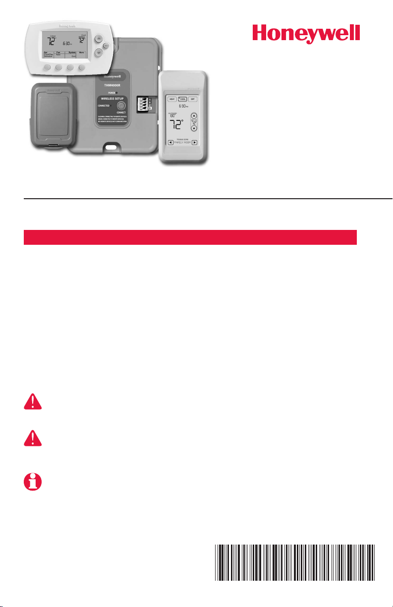
System
Installation
Guide
RedLINK™ Wireless System
With TrueZONE™ Panel & Wireless Adapter
Français : voir la page 17 • Español: vea la página 32
Provides wireless control of TrueZONE Panels. (See zone panel information
for heat/cool stage capacity. )
Installation guide for:
• FocusPRO® wireless thermostats
• Wirelessremotecontrol
• Wirelessoutdoorairsensor
DISCONNECT POWER BEFORE BEGINNING INSTALLATION. Can cause electrical
shock or equipment damage.
MERCURY NOTICE: If this product is replacing a control that contains mercury in a sealed
tube, do not place the old control in the trash. Contact your local waste
management authority for instructions regarding recycling and proper disposal.
Must be installed by a trained, experienced technician. Read these instructions carefully. Failure to follow these instructions can damage the product or cause a
hazardous condition.
® U.S. Registered Trademark.
Copyright © 2012 Honeywell International Inc.
All rights reserved.
Page 2
RedLINK™ Installation Guide (TrueZONE™)
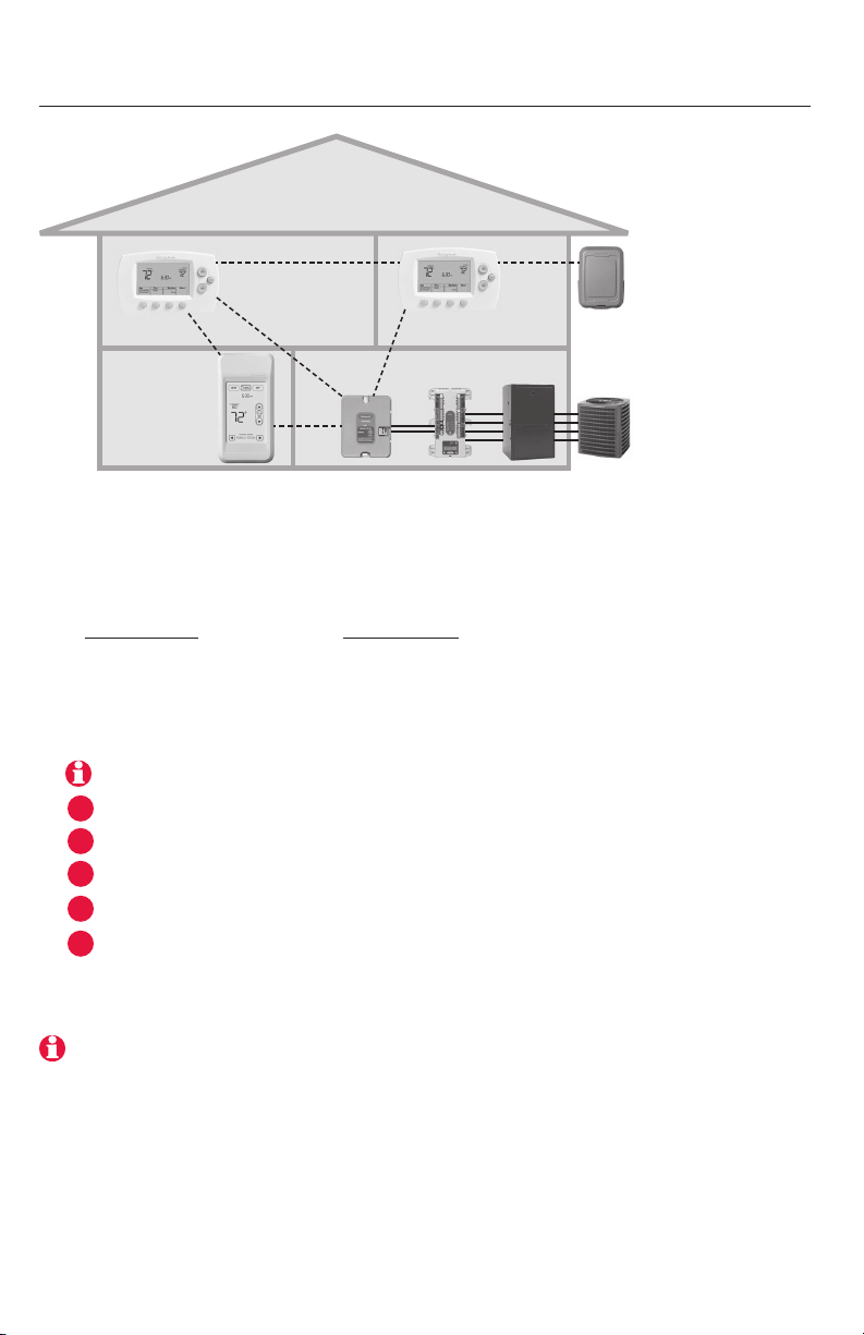
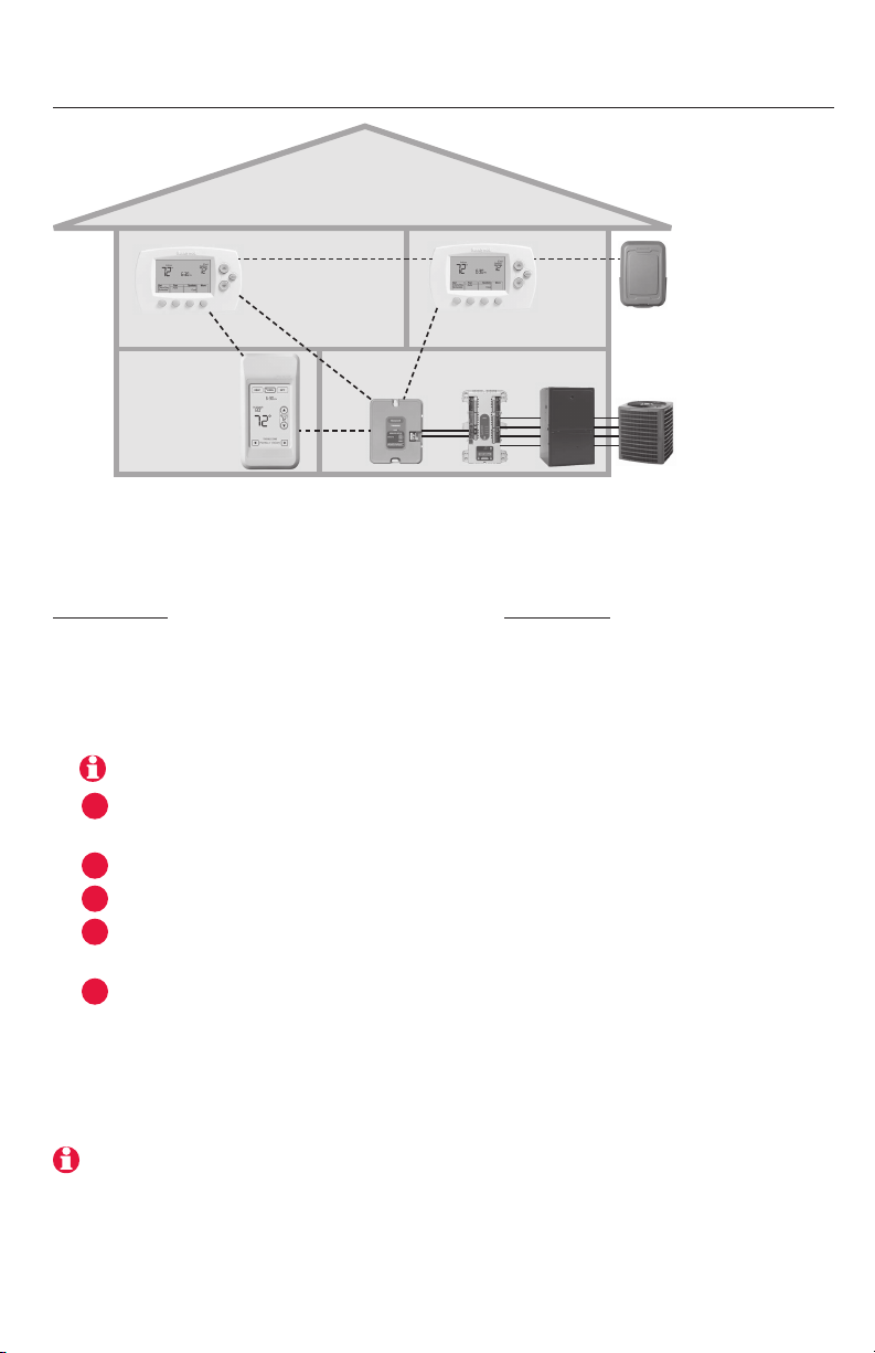
System installation at a glance
THERMOSTAT
OUTDOOR
AIR SENSOR
HVAC
EQUIPMENT
M33903
REMOTE
CONTROL
WIRELESS
ADAPTER
THERMOSTAT
TrueZONE
PANEL
Installation procedure
This document covers linking and installation procedures for FocusPRO wireless thermostats and RedLINK accessories in TrueZONE applications.
Before you begin, you must mount, wire & configure the TrueZONE panel
and wireless adapter (see TrueZONE Installation Guide), then follow steps
below.
You must configure the TrueZONE panel before you begin
1
Install batteries in wireless devices ....................................Page 3
2
Link all devices to wireless network ..............................Pages 3-5
3
Exit wireless setup ..............................................................Page 6
Customize thermostat (installer setup) ........................Pages 6-10
4
Mount thermostat and outdoor sensor .............................Page 11
5
To replace system components if needed, see page 13
If you have more than one TrueZONE Panel: Thermostats are linked to specific zone
panels. Optional accessories must be linked to each zone panel separately.
69-2090EFS—07 2
Page 3
Français : voir la page 17 • Español: vea la página 32
MCR33901
M28474
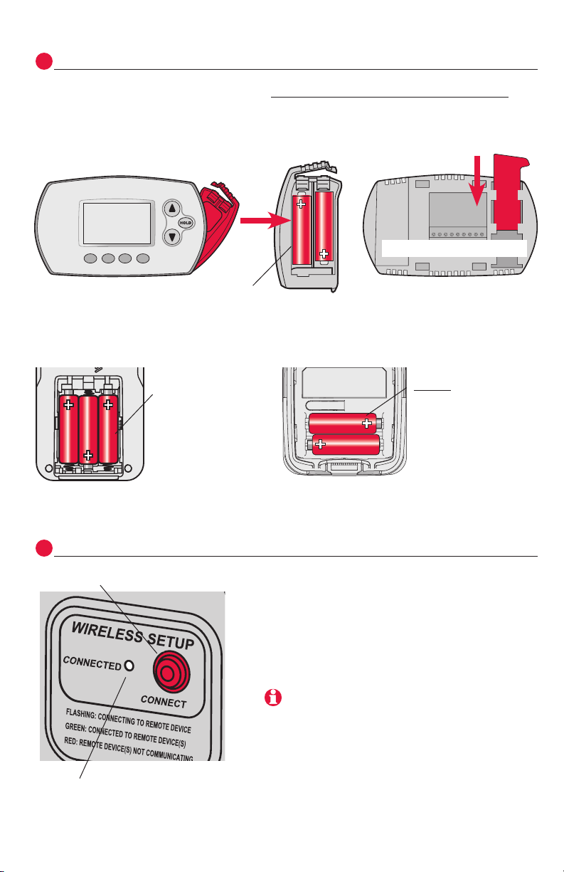
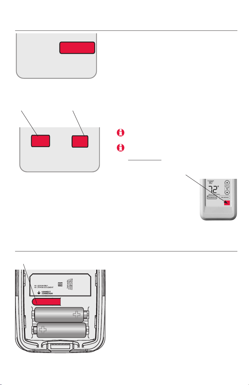
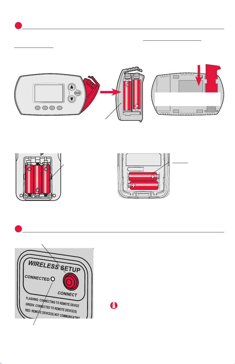
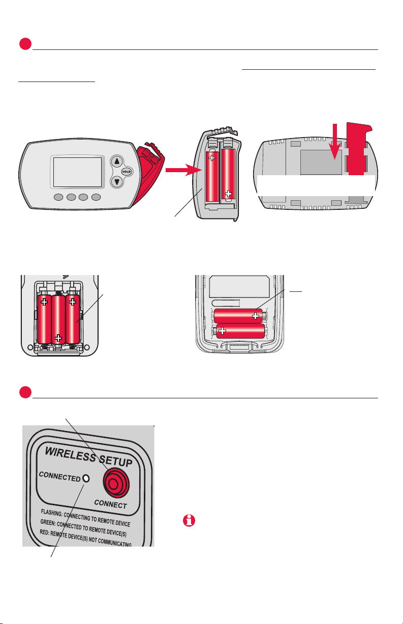
Install batteries in wireless devices
1
When system wiring is complete and TrueZONE panel is configured for RF,
install batteries in all devices. Make sure batteries are inserted properly (see
illustrations below).
Thermostat
Programmable models only
batteries
M28472
M28473
Install quick reference cardInstall 2 fresh AA
Remote control (optional) Outdoor air sensor (optional)
Install 3 fresh AA
batteries
MCR32939
Link all devices to wireless network
2
Press connect
Make sure the Connected light on the
Install 2 fresh AA
lithium batteries
M28444
wireless adapter is flashing green.
If the light stops flashing before you have
linked all devices, press connect again.
If light does not flash, another EIM/wireless
adapter may be in wireless setup mode. Exit
wireless setup at the other EIM/wireless adapter.
Flashing status light times out after 15
minutes of inactivity. Press connect again if
necessary.
3 69-2090EFS—07
Continued on next page >>
Page 4
RedLINK™ Installation Guide (TrueZONE™)
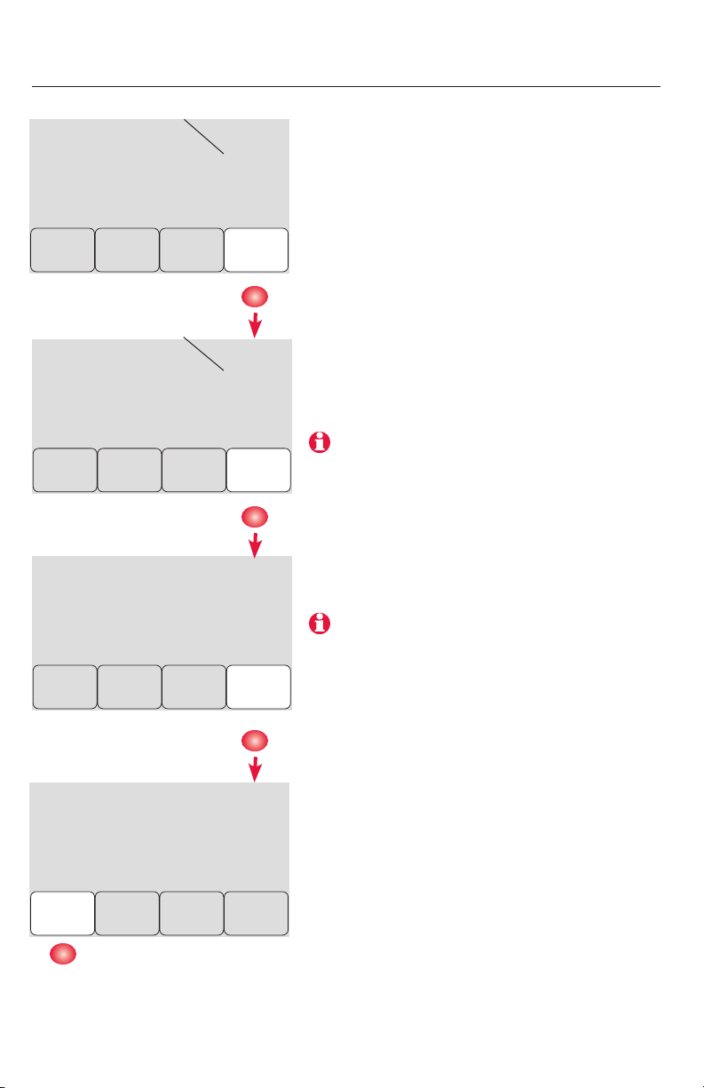
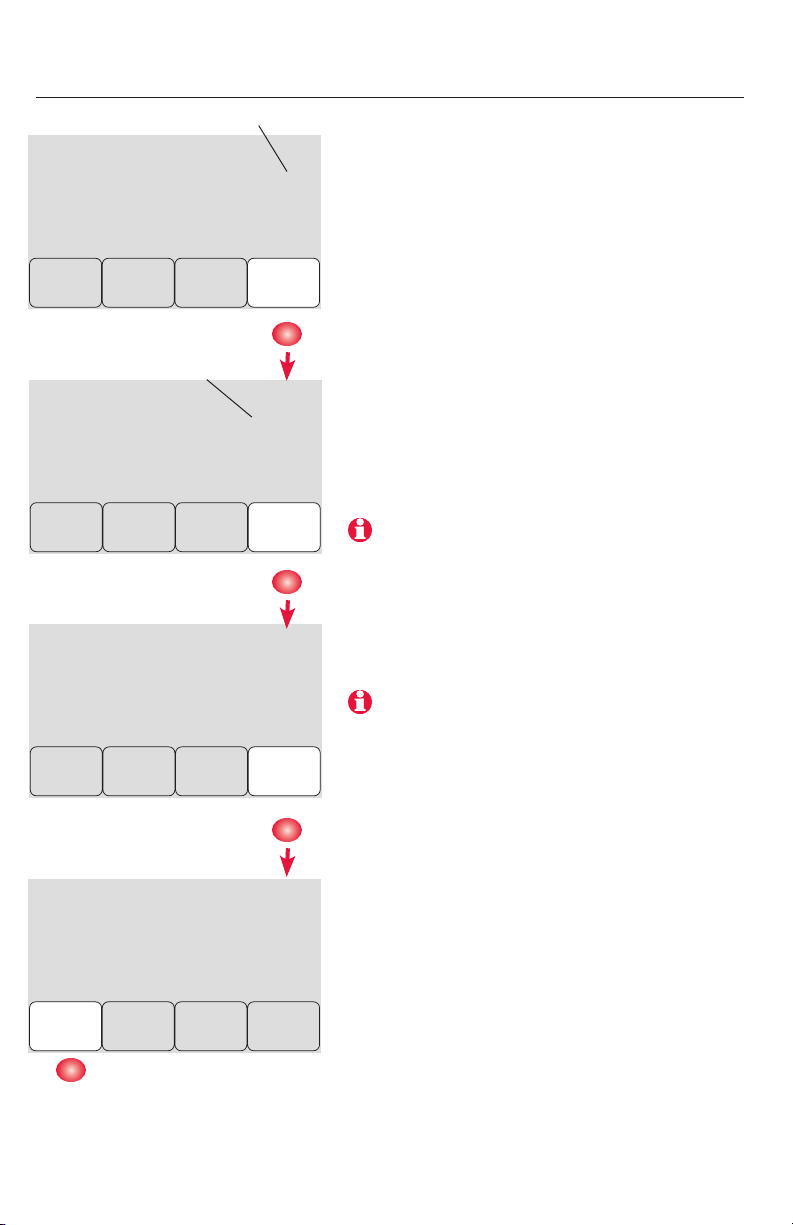
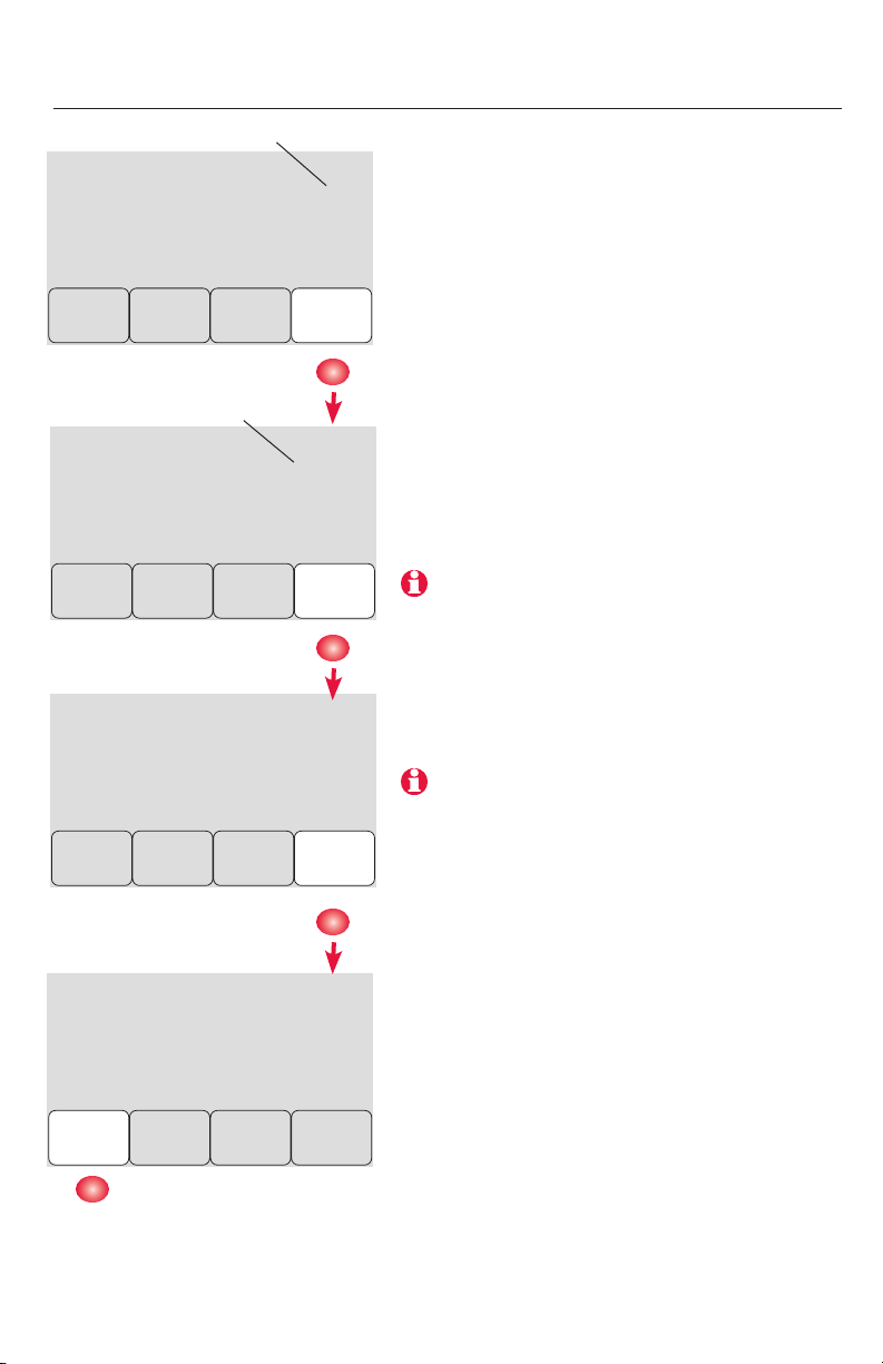
Link thermostats to wireless network
Zone number
Wireless Setup
0
Wireless Setup
36
Zone name
Back
1
Next
M28497
52
Next
Press s or t to set a zone number for this
thermostat (1 to 4), then press next.
Press s or t to change the name or
location of this zone, then press next.
Example: 31 = Living room
See complete zone list on page 8
M28478
Wireless Setup
Back
Wireless Setup
Connected
Done
69-2090EFS—07 4
Connect
M28480
Press connect to establish a link to the wireless network.
If E1 appears, see error codes on page 12.
M28479
After a brief pause, the confirmation screen
at left should be displayed, to
verify that the wireless connection has been
established.
Press done to display the home screen.
Page 5
Français : voir la page 17 • Español: vea la página 32
MCR28847A
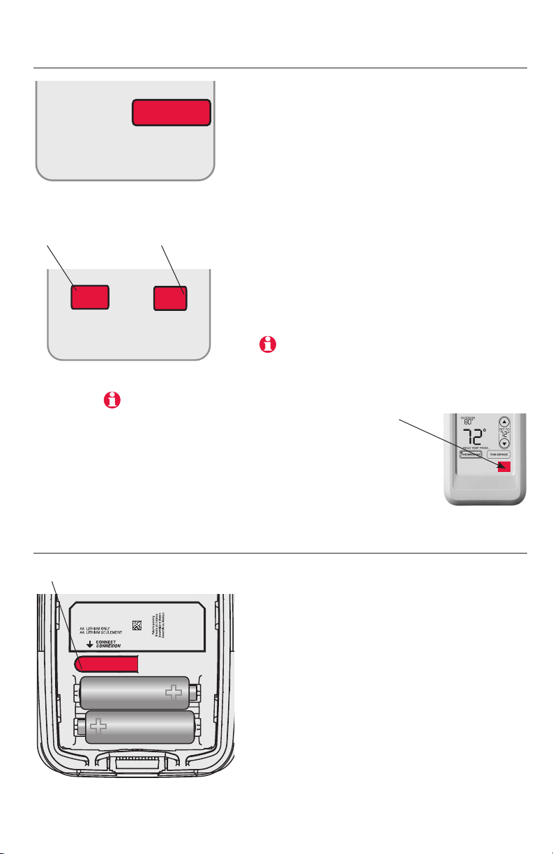
Link remote control to wireless network (optional)
1 Make sure the Connected light on the
WIRELESS SETUP
Press to link another
zone panel
CONNECT
MCR32942
Press to save
and exit
wireless adapter is flashing.
2 Press connect at the remote. There will
be a short delay as the remote seeks a
signal from the wireless network.
3 When the screen displays “Connected,”
press done.
4 Press no at the next screen to save and
exit. (Or press yes and repeat steps 1-4
to link another zone panel.)
YES
CONNECT MORE?
NO
MCR33902
If E1 appears, see error codes on page 12.
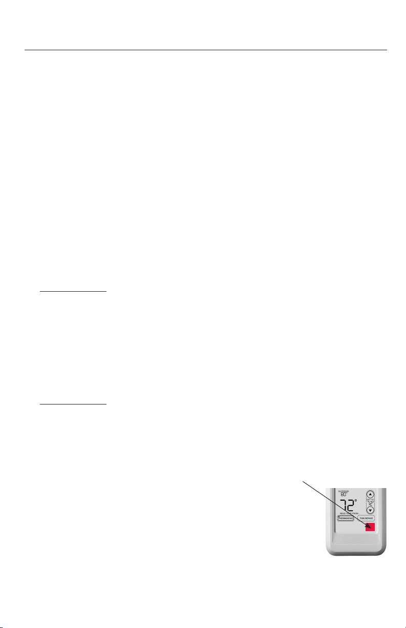
The linking procedure may time out if there is
no keypress within 30 minutes. To begin again,
press and hold the blank space (or arrow if present) in the lower right corner of the screen until
the display changes (about 3 seconds)
Link outdoor sensor to wireless network (optional)
Press and release
1 Make sure the Connected light on the
wireless adapter is flashing.
2 Press the connect button on the back of
the sensor.
3 Check thermostat to verify that the out-
door sensor is working. After about 15
seconds, the thermostat should display
outdoor temperature and humidity.
(If you are installing more than one zone
panel, repeat steps 1-3 for each.)
5 69-2090EFS—07
Page 6
RedLINK™ Installation Guide (TrueZONE™)
M28485
Exit wireless setup
3
Press connect at the wireless adapter to exit wireless setup (light should stop
flashing).
Note: The wireles adapter will automatically exit wireless setup after 15 minutes of
inactivity.
Note: If installing more than one zone panel, you must exit wireless setup before installing an
additional zone panel.
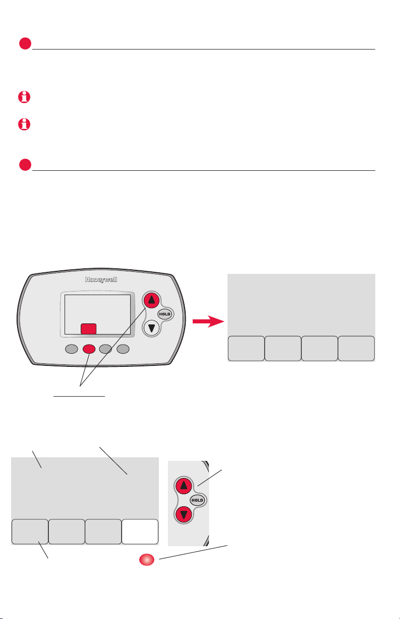
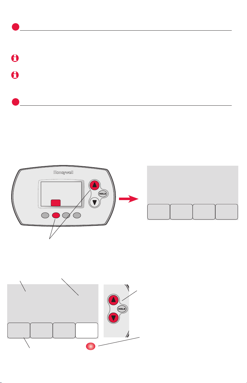
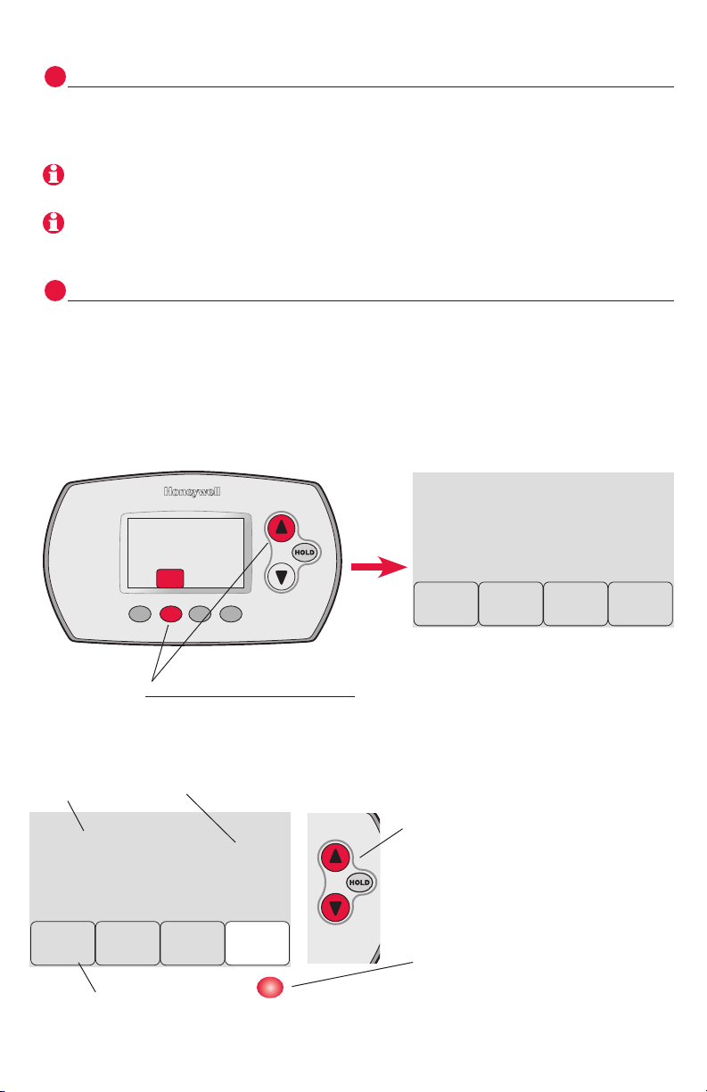
Customize thermostat (installer setup)
4
Follow the steps below to begin installer setup. At each function screen, press
s or t to change the setting as desired, then press next to advance to the next
function screen.
See tables on pages 7-9 for a description of options for each function.
FAN
To begin, press and hold the fan and s buttons
until the display changes (about 3 seconds).
Function Setting
1
Done
Press done to save & exit.
69-2090EFS—07 6
Back
0
Next
M28487
0
Done
Press s or t to change setting
(see tables on pages 7-9)
Press next to display next
function screen
Back
1
Next
M28498
Page 7
Français : voir la page 17 • Español: vea la página 32
Installer setup tables
Setup functions Settings & Options (factory default in bold)
0
Zone number
1
System type
2
Changeover valve
(O/B terminal)
3
Fan control
(conventional heat)
5
Stage 1 heat cycle
rate (CPH= cycles
per hour)
6
Stage 2 heat cycle
rate (CPH)
7
Stage 3 heat cycle
rate (CPH)
8
Emergency heat
cycle rate (CPH)
9
Stage 1 compressor cycle rate
10
Stage 2 compressor cycle rate
12
Manual/Auto
changeover
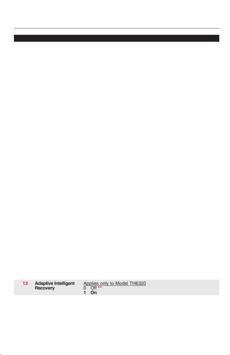
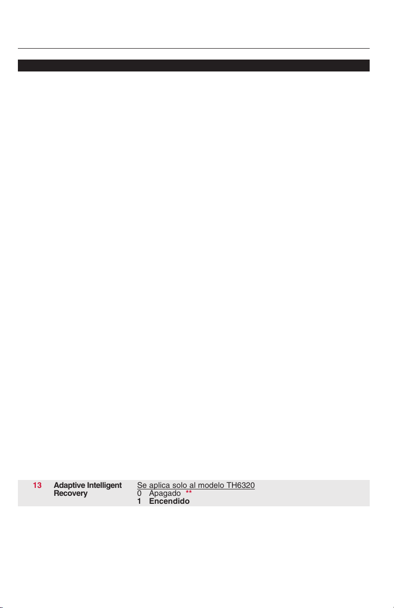
13
Adaptive Intelligent
Recovery
14
Temperature
display
0 No zoning (single thermostat used with THM5320R EIM)
[Options: select zone 1, 2, 3 or 4]
0 1 heat/1 cool conventional
1 1 heat/1 cool heat pump (no aux. heat)
2 Heat only (includes Series 20)
3 Heat only with fan
4 Cool only
5 2 heat/1 cool heat pump
6 2 heat/2 cool conventional
7 2 heat/1 cool conventional
8 1 heat/2 cool conventional
9 2 heat/2 cool heat pump
10 3 heat/2 cool heat pump
0 O/B terminal controls valve in cooling
1 O/B terminal controls valve in heating
0 Gas/Oil heat (equipment controls fan)
1 Electric furnace (thermostat controls fan)
5 Gas or oil furnaces (less than 90% efficiency)
1 Steam or gravity systems
3 Hot water systems & furnaces of over 90% efficiency
9 Electric furnaces
[Cycle rate options: 1 to 12 CPH]
5 Gas or oil furnaces (less than 90% efficiency)
1 Steam or gravity systems
3 Hot water systems & furnaces of over 90% efficiency
9 Electric furnaces
[Cycle rate options: 1 to 12 CPH]
5 Gas or oil furnaces (less than 90% efficiency)
1 Steam or gravity systems
3 Hot water systems & furnaces of over 90% efficiency
9 Electric furnaces
[Cycle rate options: 1 to 12 CPH]
9 Electric furnace
[Cycle rate options: 1 to 12 CPH]
3 Recommended cycle rate
[Cycle rate options: 1 to 6 CPH]
3 Recommended cycle rate
[Cycle rate options: 1 to 6 CPH]
0 Manual (User options: Heat/Cool/Off)
1 Automatic (User options: Heat/Cool/Auto/Off)
Applies only to Model TH6320
0 Off **
1 On
0 Fahrenheit
1 Celsius
** See page 9
7 69-2090EFS—07
Page 8

RedLINK™ Installation Guide (TrueZONE™)
Installer setup tables
Setup functions Settings & Options (factory default in bold)
15
Compressor off
time (minimum)
16
Schedule format
26
Auxiliary heat
control
27
Maximum heat
setpoint
28
Minimum cool
setpoint
32
Temp. display
offset (indoor)
33
Temp. display
offset (outdoor)
35
Humidity display
offset (outdoor)
36
Zone name
39
Wireless setup
90
RESET
5 5 minute compressor off time **
[Options: 0 to 4 minutes]
Applies only to Model TH6320
0 Weekday/weekend program schedule
1 Weekday/Saturday/Sunday program schedule
Applies only to Model TH5320
0 Comfort **
1 Economy
90 Max. heat temperature setting is 90°F (32°C)
[Options: 40 to 90°F (4.5 to 32°C)]
50 Min. cool temperature setting is 50°F (10°C)
[Options: 50 to 99°F (10 to 37°C)]
0 Thermostat displays actual temperature
[Options: -3 to +3°F offset (-1.5 to +1.5°C)]
0 Thermostat displays actual temperature
[Options: -5 to +5°F offset (-2.5 to +2.5°C)]
3 Thermostat displays actual humidity
[Other options: 0 = -15%, 1 = -10%, 2 = -5%,
4 = 5%, 5 = 10%, 6 = 15% offset]
52 Thermostat
1 Basement
2 Bathroom
3 Bathroom 1
4 Bathroom 2
5 Bathroom 3
6 Bedroom
7 Bedroom 1
8 Bedroom 2
9 Bedroom 3
10 Bedroom 4
11 Boat House
12 Bonus Room
13 Computer Room
14 Den
15 Dining Room
16 Exercise Room
17 Family Room
18 Fireplace
19 Foyer
0 Disconnect thermostat from wireless system
1 Thermostat is connected to wireless system
0 No reset
1 Reset installer options & program schedule to factory default
settings
20 Game Room
21 Garage
22 Great Room
23 Guest Room
24 Gym
25 Kid’s Room
26 Kitchen
27 Kitchen 1
28 Kitchen 2
29 Laundry Room
30 Library
31 Living Room
32 Lower Level
33 Master Bath
34 Master Bed
35 Media Room
36 Music Room
37 Nursery
38 Office
39 Office 1
40 Office 2
41 Pantry
42 Play Room
43 Pool Room
44 Porch
45 Rec Room
46 Sewing Room
47 Spa
48 Storage Room
49 Studio
50 Sun Room
51 Theater
52 Thermostat
53 Upper Level
54 Utility Room
55 Walk In Closet
56 Wine Cellar
57 Workshop
** See page 9
69-2090EFS—07 8
Page 9

Français : voir la page 17 • Español: vea la página 32
Special functions
Adaptive Intelligent Recovery (Setup Function 13): Allows the thermostat to “learn” how long the
furnace and air conditioner take to reach programmed temperature settings, so the
temperature is reached at the scheduled time.
Compressor Protection (Setup Function 15): Forces the compressor to wait a few minutes before
restarting, to prevent damage. During this time, “Heat On/Cool On” flashes on the display.
Comfort/Economy (Setup Function 26):
If you choose Comfort, auxiliary heat will respond quickly to meet the temperature setpoint. If you
choose Economy, the system will wait longer. Auxiliary heat will be activated only if the setpoint is
not reached within a reasonable time.
9 69-2090EFS—07
Page 10
RedLINK™ Installation Guide (TrueZONE™)
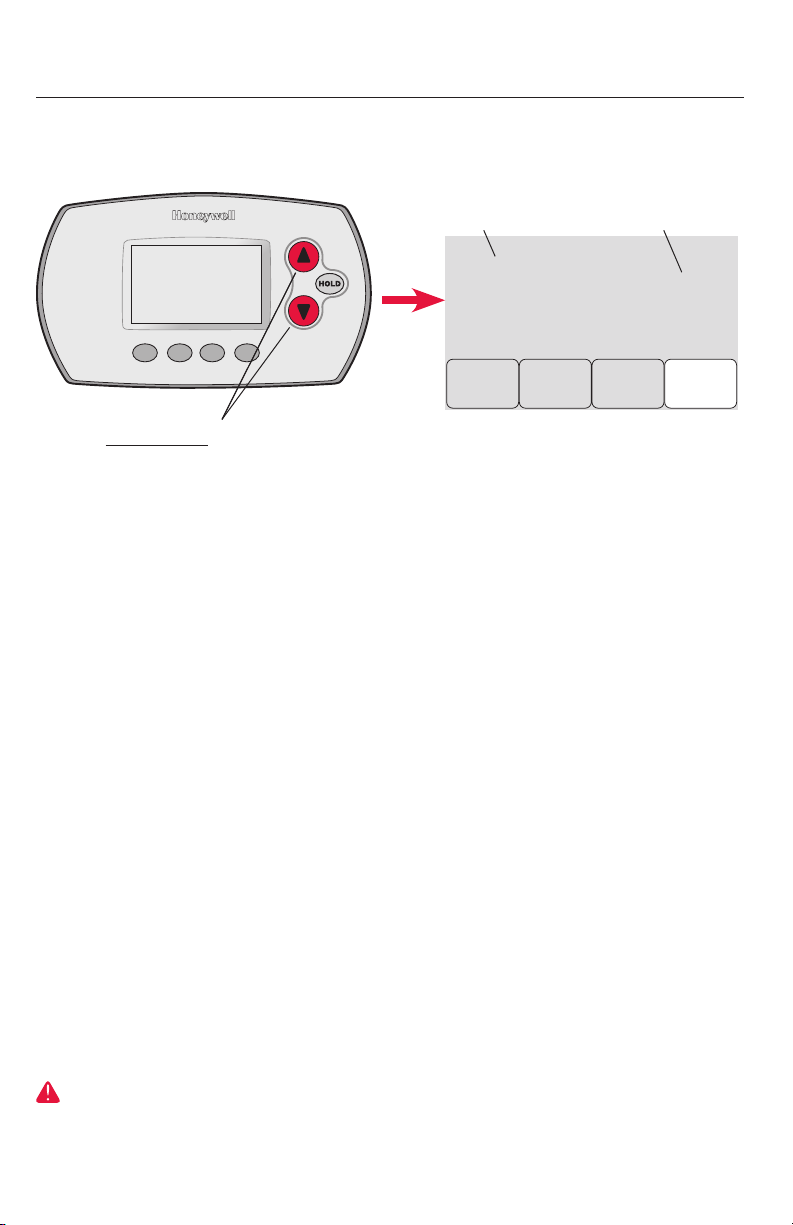
System test
Follow the procedure below to test for proper operation.
M28488
To begin, press and hold the s and t buttons
until the display changes (about 3 seconds)
System Test System Status
02
Wireless test
10
Heating system
20
Emergency
heating system
30
Cooling system
40
Fan system
70
Thermostat
information
(for reference only)
0 Off
1 Test radio signal (after a brief pause, screen displays 1-10
to show signal strength; 5 or higher recommended)
0 Heat and fan turn off
1 Heat turns on
2 Stage 2 heat turns on
3 Stage 3 heat turns on
0 Heat and fan turn off
1 Heat and fan turn on
0 Compressor and fan turn off
1 Compressor and fan turn on
2 Stage 2 compressor turns on
0 Fan turns off
1 Fan turns on
71 Software revision number (major revisions)
72 Software revision number (minor revisions)
73 Configuration identification code (major)
74 Configuration identification code (minor)
75 Production configuration date code (week)
76 Production configuration date code (year)
System test
number
02
Done
Press s or t to check system status
Press next to advance to next test
Press done to terminate system test
Back
System
status
0
Next
M28489
CAUTION: EQUIPMENT DAMAGE HAZARD. Compressor protection (minimum off time)
is bypassed during testing. To prevent equipment damage, avoid cycling the compressor
quickly.
69-2090EFS—07 10
Page 11
Français : voir la page 17 • Español: vea la página 32
M28849A
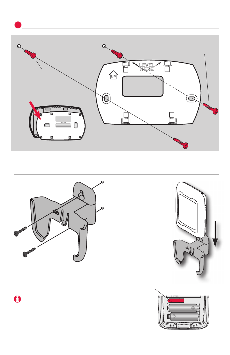
Mount thermostat & outdoor sensor
5
3/16” holes for drywal
7/32” holes for plaster
Wall anchor
Detach wallplate
Outdoor sensor (optional)
Mounting screw
Wallplate
M28490
Mount the sensor on a
vertical exterior wall,
at least 6 inches below
any overhang. Choose a
location protected from
direct sunlight.
Place sensor securely
in bracket, facing away
from wall
M28491
Press and release
To check location before mounting: Restore thermostat Home screen, then hold the sensor where
you intend to install it and press the connect button. If
sensor is working properly, thermostat will switch to
display outdoor temperature and humidity.
MCR28847A
11 69-2090EFS—07
Page 12
RedLINK™ Installation Guide (TrueZONE™)
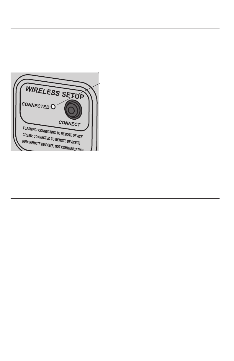
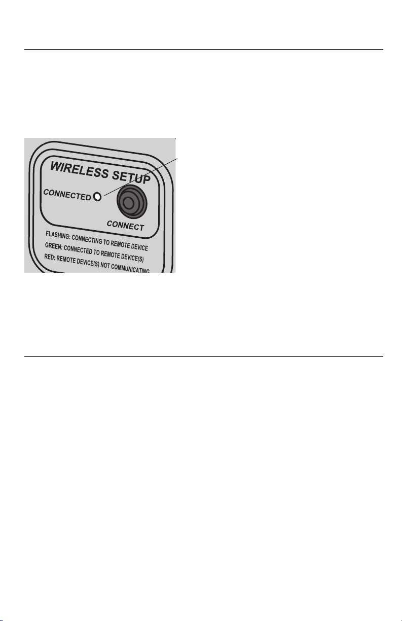
Verify proper setup
When wireless setup is complete, make sure the Connected light on the wireless adapter is solid green (see below), then follow the steps in the Checkout
section of the TrueZONE installation guide to verify proper
operation.
Wireless status light
• Solid green: wireless adapter is
working properly and communicating
with wireless devices.
• Flashing green: Linking to wireless
devices (light flashes for 15 minutes
after you press connect).
• Solid red: Communication problem.
Check wireless adapter and other wireless devices.
M33901
Error codes (thermostat & remote control)
If E1 appears during setup, check error code number (right side of screen):
29 Attempting to connect incompatible wireless devices.
30 Verify that thermostat zone number matches number assigned at zone panel.
31 Verify that this zone number is configured at the zone panel as an RF thermostat.
34 Low signal strength. Move wireless device to a different location and try again.
38 Make sure Connected light on wireless adapter is flashing and you are 2+ feet away from
wireless adapter.
69-2090EFS—07 12
Page 13
Français : voir la page 17 • Español: vea la página 32
Replacing system components
Thermostat
To replace a thermostat, install batteries and follow the procedure on page 4
to link it to the wireless network. If necessary, modify settings as needed (see
tables on pages 7-9).
Remote control & outdoor sensor
To replace a remote control or outdoor air sensor, install batteries and
follow the procedure on page 5 to link it to the wireless network.
TrueZONE panel & wireless adapter
After installing a new zone panel or wireless adapter, you must re-set the
thermostat and remote control to communicate with the new equipment, as
described below.
At the thermostat:
1 Press and hold the fan and s buttons for 3 seconds.
2 Press back twice to display Function 39 (wireless setup).
3 Press t to change Function 39 setting to 0 (disconnect from old
equipment).
4 Follow the procedure on page 4 to link to new equipment.
At the remote control:
1 Press and hold the blank space (or arrow if present) in the lower right
corner of the screen until the display changes (about 3 seconds).
2 Press remove , then yes to disconnect from old equipment.
3 Follow the procedure on page 5 to link to new equipment.
Press and hold for
about 3 seconds
13 69-2090EFS—07
Page 14

RedLINK™ Installation Guide (TrueZONE™)
Specifications & replacement parts
Operating Ambient Temperature
Thermostat: 32 to 120° F (0 to 48.9° C)
Remote control: 32 to 120° F (0 to 48.9° C)
Wireless Adapter: -40 to 165° F (-40 to 73.9° C)
Outdoor air sensor: -40 to 140° F (-40 to 60° C)
Operating Relative Humidity
Thermostat: 5% to 90% (non-condensing)
Remote control: 5% to 90% (non-condensing)
Wireless Adapter: 5% to 95% (non-condensing)
Outdoor air sensor: 0% to 100% (condensing)
Physical Dimensions (height, width, depth)
Thermostat: 3-9/16 x 5-13/16 x 1-1/2 inches (91 x 147 x 38 mm)
Wireless Adapter: 5-9/16 x 4-3/8 x 1-1/4 inches (141 x 112 x 32 mm)
Outdoor air sensor: 5 x 3-1/2 x 1-11/16 inches (127 x 89 x 43 mm)
Accessories & Replacement Parts
Item Part Number
Wireless adapter THM4000R1000
FocusPRO® wireless thermostat (programmable) TH6320R1004
FocusPRO® wireless thermostat (non-programmable) TH5320R1002
Remote control REM5000R1001
Outdoor air sensor C7089R1013
Battery holder 50007072-001
Cover plate (covers marks left by old thermostats) 50002883-001
69-2090EFS—07 14
Page 15

Français : voir la page 17 • Español: vea la página 32
Regulatory information
FCC Compliance Statement (Part 15.19) (USA only)
This device complies with Part 15 of the FCC Rules. Operation is subject to the following two conditions:
1 This device may not cause harmful interference, and
2 This device must accept any interference received, including interference that may cause unde-
sired operation.
FCC Warning (Part 15.21) (USA only)
Changes or modifications not expressly approved by the party responsible for compliance could
void the user’s authority to operate the equipment.
FCC Interference Statement (Part 15.105 (b)) (USA only)
This equipment has been tested and found to comply with the limits for a Class B digital device,
pursuant to Part 15 of the FCC Rules. These limits are designed to provide reasonable protection
against harmful interference in a residential installation. This equipment generates uses and can
radiate radio frequency energy and, if not installed and used in accordance with the instructions,
may cause harmful interference to radio communications. However, there is no guarantee that
interference will not occur in a particular installation. If this equipment does cause harmful interference to radio or television reception, which can be determined by turning the equipment off and on,
the user is encouraged to try to correct the interference by one of the following measures:
• Reorientorrelocatethereceivingantenna.
• Increasetheseparationbetweentheequipmentandreceiver.
• Connecttheequipmentintoanoutletonacircuitdifferentfromthattowhichthereceiveriscon-
nected.
• Consultthedealeroranexperiencedradio/TVtechnicianforhelp.
Wireless adapter, thermostats and outdoor sensor
To comply with FCC and Industry Canada RF exposure limits for general population/ uncontrolled
exposure, the antenna(s) used for these transmitters must be installed to provide a separation
distance of at least 20 cm from all persons and must not be co-located or operating in conjunction
with any other antenna or transmitter.
Remote control
This portable transmitter with its antenna complies with FCC and Industry Canada RF
exposure limits for general population/uncontrolled exposure.
Section 7.1.5 of RSS-GEN
Operation is subject to the following two conditions:
1 this device may not cause interference, and
2 this device must accept any interference, including interference that may cause undesired
operation of the device.
15 69-2090EFS—07
Page 16

RedLINK™ Installation Guide (TrueZONE™)
69-2090EFS—07 16
Page 17
Guide
d’installation
du système
Système sans fil RedLINK™
avec tableau TrueZONE™ et adaptateur sans fil
English: see page 1 • Español: vea la página 32
Pour la commande sans fil des tableaux TrueZONE.
(Voir l’information sur le tableau de zonage pour connaître le nombre
d’étages de chauffage-refroidissement.)
Guide d’installation pour :
• ThermostatsansfilFocusPRO®
• Télécommandesansfil
• Capteurd’airextérieursansfil
COUPER L’ALIMENTATION ÉLECTRIQUE AVANT D’EFFECTUER LE
RACCORDEMENT. Peut provoquer des chocs électriques ou endommager le matériel.
AVIS SUR LE MERCURE : Si le nouveau thermostat remplace un ancien régulateur
contenant un contact à mercure, ne pas mettre l’ancien régulateur aux poubelles.
Communiquer avec le service local de cueillette des déchets pour obtenir de l’information
sur le recyclage ou sur la bonne façon de disposer d’un ancien régulateur contenant un
contact à mercure.
Doit être installé par un technicien d’expérience ayant reçu la formation
pertinente. Lire attentivement les instructions. Le fait de ne pas les suivre risque
d’endommager le produit ou de constituer un danger.
® Marque de commence enregistrée aux États-Unis.
Copyright © 2012 Honeywell International Inc.
Tous droits réservés.
Page 18

Système sans fil RedLINK™ (TrueZONE™)
Installation du système en un coup d’oeil
THERMOSTAT
CAPTEUR
D’AIR
EXTÉRIEUR
MATÉRIEL
DE CVCA
MF33903
TÉLÉCOMMANDE
ADAPTATEUR
SANS FIL
THERMOSTAT
TABLEAU
TrueZONE
Installation
Le présent document porte sur la connexion et l’installation de thermostats
FocusPRO et d’accessoires REDLINK sans fil au sein d’une application
TrueZONE.
Avant de commencer, il faut installer, raccorder et configurer le tableau
TrueZONE et l’adaptateur sans fil (voir le Guide d’installation TrueZone), puis
suivre les étapes ci-dessous.
Configurer le tableau TrueZONE avant de commencer
1
Insertion des piles dans l’appareil sans fil ........................Page 33
2
Relier tous les appareils au réseau sans fil ..............Pages 33-35
Quitter la configuration des appareils sans fil ..................Page 36
3
Personnaliser (configuration par l’installateur) ..........Pages 36-40
4
Installation du thermostat et du capteur extérieur ............Page 41
5
Pour remplacer les composants du système au besoin, voir la page 43
S’il y a plus d’un module d’interface avec le matériel (EIM) : Les thermostats sont liés à
des modules d’interface particuliers. Les accessoires en option doivent être liés à chaque EIM
séparément.
69-2090EFS—07 18
Page 19
English: see page 1 • Español: vea la página 32
M28474
M28473
Insertion des piles dans l’appareil sans fil
1
Une fois le raccordement du système terminé et le tableau TrueZONE
configuré à RF, installer les piles dans tous les dispositifs. S’assurer qu’elles
sont installées correctement (Voir illustration ci-dessous).
Thermostat
Thermostats programmables
M28472
neuves
seulement
Insérer l’aide-mémoire Insérer 2 piles AA
Télécommande (optionnelle) Capteur d’air extérieur (optionnel)
Insérer 3 piles AA
neuves
MCR32939
Relier tous les appareils au réseau sans fil
2
Appuyer sur connect
S’assurer que le voyant vert Connected
Insérer 2 piles au
lithium AA neuves
M28444
de l’adaptateur sans fil clignote. Si le voyant cesse de clignoter avant que tous les
appareils soient reliés, appuyer à nouveau
sur le bouton connect.
Si le voyant ne clignote pas, il se pourrait qu’un
autre EIM/adaptateur sans fil soit en mode de
MCR33901
Le voyant d’état cesse de clignoter après
15 minutes d’inactivité. Appuyer sur le bouton connect à nouveau au besoin.
19 69-2090EFS—07
configuration d’un appareil sans fil. Quitter le
mode de configuration à l’autre EIM ou adaptateur sans fil.
À suivre >>
Page 20
Système sans fil RedLINK™ (TrueZONE™)
Relier le thermostat au réseau sans fil
Numéro de zone
Wireless Setup
0
Wireless Setup
36
1
Next
M28497
Nom de zone
52
Appuyer sur s ou t pour régler un numéro
de zone pour ce thermostat (1 à 4), puis
appuyer sur next.
Appuyer sur s ou t pour modifier le nom
ou l’emplacement de cette zone, puis
appuyer sur next.
Exemple : 31 = Living Room
Done
Back
Wireless Setup
Back
Wireless Setup
Connected
Next
M28478
Connect
M28479
M28480
Voir la liste complète des zones à la page 38.
Appuyer sur connect pour établir un lien avec
le réseau sans fil.
Si l’écran affiche E1, voir les codes d’erreur à la
page 42.
Après une courte pause, l’écran de confirmation à gauche devrait apparaître, indiquant que la connexion sans fil a bien été
établie.
Appuyer sur done pour revenir à l’écran
d’accueil.
69-2090EFS—07 20
Page 21
English: see page 1 • Español: vea la página 32
MCR28847A
Relier la télécommande au réseau sans fil (optionnel)
1 S’assurer que le voyant Connected de
l’adaptateur sans fil clignote.
2 Appuyer sur connect de la télécom-
mande. Il y a aura un court délai pendant que la télécommande recherche le
signal du réseau sans fil.
3 Lorsque l’écran affiche «Connected»,
appuyer sur done.
4 Appuyer sur no à l’écran suivant pour
sauvegarder la configuration et
quitter. (Ou appuyer sur yes et répéter
les étapes 1 à 4 pour relier un autre
tableau de zonage.)
WIRELESS SETUP
Appuyer pour relier
un autre EIM
YES
CONNECT
MCR32942
Appuyer pour
enregistrer et
quitter
NO
CONNECT MORE?
MCR33902
Le raccordement au réseau sans fil peut prendre fin
automatiquement après 30 minutes d’inactivité sur les
touches. Pour recommencer, appuyer sur l’espace
vierge (ou sur la flèche, selon le cas) dans le coin
inférieur droit de l’écran jusqu’à ce que l’écran change
(au bout d’environ 3 secondes).
Si l’écran affiche E1, voir les codes d’erreur à la
page 42.
Relier le capteur d’air extérieur au réseau sans fil (optionnel)
Appuyer et le relâcher
1 S’assurer que le voyant Connected du
EIM clignote (voir la page 43).
2 Appuyer sur le bouton connect à l’arrière
du capteur.
3 Observer le thermostat pour vérifier
que le capteur d’air extérieur fonctionne. Après environ 15 secondes, le
thermostat devrait afficher la température et l’humidité extérieures.
(S’il y a plus d’un EIM à installer, répéter
les étapes 1 à 3 pour chacun.)
21 69-2090EFS—07
Page 22
Système sans fil RedLINK™ (TrueZONE™)
M28485
Quitter la configuration du réseau sans fil
3
Appuyer sur connect au EIM pour quitter la configuration du réseau sans fil (le
voyant devrait cesser de clignoter).
Remarque : Le EIM quittera automatiquement la configuration du réseau sans fil après 15
minutes d’activité.
Remarque : Lors de l’installation de plus d’un thermostat et plus d’un EIM, il faut quitter la configuration du réseau sans fil avant l’installation d’un thermostat et d’un EIM additionnels.
Personnalisation (mode de configuration par l’installateur)
4
Suivre les étapes ci-dessous pour commencer la configuration. À chaque écran
de fonction, appuyer sur s ou t pour obtenir le réglage désiré, puis appuyer
sur next pour passer à l’écran de fonction suivant.
Voir les tableaux aux pages 39 à 40 pour obtenir une description de
chacune des fonctions.
FAN
Appuyer les boutons fan et s jusqu’à ce que
l’affichage change (au bout d’environ 3 secondes).
Fonction Réglage
1
Done
Appuyer sur done pour enregistrer et quitter.
69-2090EFS—07 22
Back
0
Next
M28487
0
Done
Appuyer sur s ou t pour modifier le
réglage (voir les pages 39 à 40).
Appuyer sur next pour faire afficher
l’écran de fonction suivant.
Back
1
Next
M28498
Page 23
English: see page 1 • Español: vea la página 32
Tableaux de configuration par l’installateur
Fonctions Options (réglages de l’usine en gras)
0
Numéro de zone
1
Type de système
2
Vanne d’inversion
(borne O/B)
3
Ventilateur (chauffage
classique)
5
Cycles de chauffage
(étage 1) CPH= cycles
par heure
6
Cycles de chauffage
(étage 2) (CPH)
7
Cycles de chauffage
(étage 3) (CPH)
8
Cycles de chauffage
d’urgence (CPH)
9
Cycles de compresseur (étage 1)
10
Cycles de compres-
seur (étage 2)
12
Commutation chaudfroid manuelle/auto
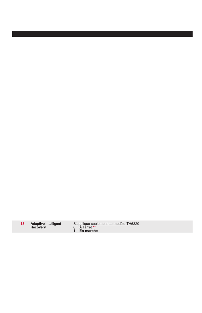
13
Adaptive Intelligent
Recovery
14
Affichage de la
température
0 Pas de zonage (un seul thermostat employé avec le EIM THM5320R
[Options : sélectionner la zone 1, 2, 3 ou 4]
0 Chauffage-refroidissement classique 1 chaud/1 froid
1 Thermopompe 1 chaud/1 froid (sans chauffage auxiliaire)
2 Chauffage seulement (y compris Série 20)
3 Chauffage seulement avec ventilateur
4 Refroidissement seulement
5 Thermopompe 2 chaud/1 froid
6 Chauffage-refroidissement classique 2 chaud/2 froid
7 Chauffage-refroidissement classique 2 chaud/1 froidl
8 Chauffage-refroidissement classique 1 chaud/2 froid
9 Thermopompe 2 chaud/2 froid
10 Thermopompe 3 chaud/2 froid
0 La borne O/B fait passer la vanne au mode de refroidissement
1 La borne O/B fait passer la vanne au mode de chauffage
0 Chauffage au gaz/mazout (ventilateur commandé par le système)
1 Chauffage à l’électricité (ventilateur commandé par le thermostat)
5 Chauffage au gaz ou au mazout (< 90 % d’efficacité)
1 Systèmes à vapeur ou à gravité
3 Systèmes à eau chaude et appareils de chauffage > 90 % d’efficacité
9 Appareils de chauffage électriques
[Options de cycles par heure : 1 à 12]
5 Chauffage au gaz ou au mazout (< 90 % d’efficacité)
1 Systèmes à vapeur ou à gravité
3 Systèmes à eau chaude et appareils de chauffage > 90 % d’efficacité
9 Appareils de chauffage électriques
[Options de cycles par heure : 1 à 12]
5 Chauffage au gaz ou au mazout (< 90 % d’efficacité)
1 Systèmes à vapeur ou à gravité
3 Systèmes à eau chaude et appareils de chauffage > 90 % d’efficacité
9 Appareils de chauffage électriques
[Options de cycles par heure : 1 à 12]
9 Appareils de chauffage électriques
[Options de cycles par heure : 1 à 12]
3 Cycles par heure recommandés
[Options de cycles par heure : 1 à 6]
3 Cycles par heure recommandés
[Options de cycles par heure : 1 à 6]
0 Manuel (Options de l’utilisateur : Heat/Cool/Off)
1 Automatique (Options de l’utilisateur : Heat/Cool/Auto/Off)
S’applique seulement au modèle TH6320
0 À l’arrêt **
1 En marche
0 Fahrenheit
1 Celsius
** Voir la page 41
23 69-2090EFS—07
Page 24

Système sans fil RedLINK™ (TrueZONE™)
Tableaux de configuration par l’installateur
Fonctions Options (réglages de l’usine en gras)
15
Temps d’arrêt du
compresseur (min.)
16
Type de programme
26
Régulation du
chauffage auxiliaire
27
Point de consigne de
chauffage (max.)
28
Point de consigne de
refroidissement (min.)
32
Écart avec la temp.
affichée (intérieure)
33
Écart avec la temp.
affichée (extérieure)
35
Écart avec l’humidité
affichée (extérieure)
36
Nom de la zone
39
Configuration
sans fil
90
RÉARMER
5 5 minutes (les mots «Heat On/Cool On» clignotent à l’écran )
[Options : 0 à 4 minutes]
S’applique seulement au modèle TH6320
0 Horaire de semaine/fin de semaine
1 Horaire de semaine/samedi/dimanche
S’applique seulement au modèle TH5320
0 Confort **
1 Économique
90 Point de consigne de chauffage maximal de 90 °F (32 °C)
[Options : 40 à 90 °F (4,5 à 32 °C)]
50 Point de consigne de refroidissement minimal de 50 °F (10 °C)
[Options : 50 à 99 °F (10 à 37 °C)]
0 Le thermostat affiche la température réelle
[Options : -3 à +3 °F d’écart (-1.5 à +1.5 °C)]
0 Le thermostat affiche la température réelle
[Options : -5 à +5 °F d’écart (-2.5 à +2.5 °C)]
3 Le thermostat affiche l’humidité réelle
[Options : 0 = -15 %, 1 = -10%, 2 = -5 %,
4 = 5 %, 5 = 10 %, 6 = 15 % d’écart]
52 Thermostat
1 Basement
2 Bathroom
3 Bathroom 1
4 Bathroom 2
5 Bathroom 3
6 Bedroom
7 Bedroom 1
8 Bedroom 2
9 Bedroom 3
10 Bedroom 4
11 Boat House
12 Bonus Room
13 Computer Room
14 Den
15 Dining Room
16 Exercise Room
17 Family Room
18 Fireplace
19 Foyer
20 Game Room
21 Garage
22 Great Room
23 Guest Room
24 Gym
25 Kid’s Room
26 Kitchen
27 Kitchen 1
28 Kitchen 2
29 Laundry Room
30 Library
31 Living Room
32 Lower Level
33 Master Bath
34 Master Bed
35 Media Room
36 Music Room
37 Nursery
38 Office
0 Débrancher le thermostat du réseau sans fil
1 Thermostat relié au réseau sans fil
0 Pas de réarmement
1 Réarmer les options de l’installateur et le programme aux
réglages de l’usine
39 Office 1
40 Office 2
41 Pantry
42 Play Room
43 Pool Room
44 Porch
45 Rec Room
46 Sewing Room
47 Spa
48 Storage Room
49 Studio
50 Sun Room
51 Theater
52 Thermostat
53 Upper Level
54 Utility Room
55 Walk In Closet
56 Wine Cellar
57 Workshop
** Voir la page 41
69-2090EFS—07 24
Page 25

English: see page 1 • Español: vea la página 32
Fonctions spéciales
Adaptive Intelligent Recovery (Configuration de la fonction 13) : Permet au thermostat
«d’apprendre» combien de temps il faut au système de chauffage ou de refroidissement pour
atteindre la température souhaitée pour que la température désirée soit atteinte à l’heure prévue.
Protection du compresseur (Configuration de la fonction 15) : Cette fonction oblige le
compresseur à attendre quelques minutes avant de redémarrer . Pendant ce temps, les mots
«HeatOn/Cool On» clignotent à l’écran.
Confort/Économie (Configuration de la fonction 26) :
En mode confort, le chauffage auxiliaire réagira rapidement pour atteindre le point de consigne de
température. En mode économie, le système attendra plus longtemps. Le chauffage auxiliaire ne
sera activé que si le point de consigne n’est pas atteint au bout d’un temps raisonnable.
25 69-2090EFS—07
Page 26

Système sans fil RedLINK™ (TrueZONE™)
Test du système
Suivre les étapes ci-dessous pour vérifier le bon fonctionnement du système.
Appuyer sur les boutons s et t jusqu’à ce
que l’affichage change (au bout d’environ 3
secondes).
Appuyer sur s ou t pour vérifier l’état du système
Appuyer sur next pour passer au test suivant
Appuyer sur done pour mettre fin à la vérification
Test du système État du système
02
Test du réseau
sans fil
10
Système de
chauffage
20
Système de
chauffage d’urgence
30
Système de
refroidissement
40
Ventilateur
70
Information sur le
thermostat
(pour référence
seulement)
0 À l’arrêt
1 Vérifier le signal radio (après une courte pause, l’écran affiche
1-10 pour indiquer la force du signal; 5 ou plus recommandé)
0 Le système de chauffage et le ventilateur se mettent à l’arrêt
1 Le système de chauffage se met en marche (étage 1)
2 Le système de chauffage se met en marche (étage 2)
3 Le système de chauffage se met en marche (étage 3)
0 Le système de chauffage et le ventilateur se mettent à l’arrêt
1 Le système de chauffage et le ventilateur se mettent en marche
0 Le compresseur et le ventilateur se mettent à l’arrêt
1 Le compresseur et le ventilateur se mettent en marche
2 compresseur se met en marche (étage 2)
0 Le ventilateur se met à l’arrêt
1 Le ventilateur se met en marche
71 Numéro de révision du logiciel (révisions majeures)
72 Numéro de révision du logiciel (révisions mineures)
73 Code d’identification de la configuration (majeure)
74 Code d’identification de la configuration (mineure)
75 Code de date de la configuration à la fabrication (semaine)
76 Code de date de la configuration à la fabrication (année)
Numéro de test
du système
02
Done
Back
État du système
0
Next
M28489
MISE EN GARDE : RISQUE DE DOMMAGE MATÉRIEL. Le système ne tient pas compte
du temps d’arrêt minimal du compresseur pendant le test par l’installateur. Pour éviter
d’endommager le matériel, éviter les cycles de fonctionnement trop rapides du compresseur.
69-2090EFS—07 26
Page 27

English: see page 1 • Español: vea la página 32
MCR28847A
Installer le thermostat et le capteur extérieur
5
3/16 po si le mur est en placoplâtre
7/32 po si le mur est en plâtre
Cheville
d’ancrage
Détacher la plaque murale
Plaque murale
Capteur extérieur (optionnel)
Vis de fixation
M28490
Installer le capteur sur
un mur extérieur à la
verticale, à au moins
6 pouces (15 cm) de
tout surplomb. Choisir
un emplacement où le
capteur sera à l’abri des
rayons du soleil.
Fixer fermement le
capteur sur le support,
en mettant le dos de
l’appareil contre le mur.
M28491
M28849A
Appuyer et le relâcher
Pour vérifier l’emplacement avant l’installation :
Revenir à l’écran d’accueil du thermostat, tenir le
capteur à l’endroit où l’on souhaite l’installer et appuyer
sur le bouton connect. Si le capteur fonctionne correctement, le thermostat passera à l’affichage de la température et de l’humidité extérieures.
27 69-2090EFS—07
Page 28

Système sans fil RedLINK™ (TrueZONE™)
Vérifier la configuration
Lorsque la configuration du réseau sans fil est terminée, s’assurer que le voyant vert Connect reste allumé à l’adaptateur sans fil (voir ci-dessous), puis
suivre les étapes de la section Vérification du guide d’installation TrueZONE
pour vérifier le bon fonctionnement.
Voyant d’état du réseau sans fil
• Allumé vert en continu : l’adaptateur
sans fil fonctionne correctement et communique avec les appareils sans fil.
• Vert clignotant : Établit le lien avec le
réseau sans fil (le voyant clignote pendant 15 minutes après que l’utilisateur
ait appuyé sur le bouton connect).
• Allumé rouge en continu : Problème
de communication. Vérifier l’adaptateur
M33901
sans fil et les autres appareils sans fil.
Codes d’erreur (thermostat et télécommande)
Si l’écran affiche E1 au cours de l’installation, vérifier le numéro du code d’erreur
(dans la partie droite de l’écran) :
29 Tentative de configuration d’appareils incompatibles.
30 Vérifier si le numéro du thermostat de zone correspond au numéro attribué au tableau de
zonage.
31 Vérifier si le numéro de zone est configuré au tableau de zonage en tant que thermostat à
radiofréquences.
34 Signal trop faible. Déplacer l’appareil sans fil à un autre endroit et essayer à nouveau.
38 S’assurer que les voyants Connect de l’adaptateur sans fil clignotent et que le
thermostat ou la télécommande sont à 2 pieds et plus de l’adaptateur sans fil.
69-2090EFS—07 28
Page 29

English: see page 1 • Español: vea la página 32
Remplacement des composants du système
Thermostat
Pour remplacer un thermostat, insérer des piles neuves dans le nouvel appareil et suivre les étapes décrites à la page 34 pour le relier au réseau sans fil.
Au besoin, modifier les paramètres (voir les tableaux aux pages
37 à 39).
Télécommande et capteur extérieur
Pour remplacer une télécommande ou un capteur d’air extérieur, insérer des
piles neuves dans le nouvel appareil et suivre les étapes décrites à la page 5
pour le relier au réseau sans fil.
Tableau TrueZONE et adaptateur sans fil
Après l’installation d’un nouveau tableau de zonage ou adaptateur sans fil, il
faut réarmer le thermostat pour qu’il puisse communiquer avec le
nouveau matériel, selon la description qui suit.
Au thermostat :
1 Appuyer pendant environ 3 secondes sur les boutons fanet▲s .
2 Appuyer sur le bouton back deux fois pour afficher la fonction 39
(configuration du réseau sans fil).
3 Appuyersur▲t pour faire passer le paramètre 39 au réglage 0
(se déconnecter de l’ancien matériel).
4 Suivre les étapes à la page 34 pour connecter le nouvel appareil
au réseau.
À la télécommande :
1 Appuyer environ 3 secondes sur l’espace vierge (ou la flèche, selon le cas)
dans le coin inférieur droit de l’écran jusqu’à ce que l’affichage change.
2 Appuyer sur le bouton remove, puis sur yes pour déconnecter l’ancien maté-
riel.
3 Suivre les étapes à la page 35 pour connecter le nouvel appareil au réseau.
Appuyer sur le bouton
environ 3 secondes
29 69-2090EFS—07
Page 30

Système sans fil RedLINK™ (TrueZONE™)
Caractéristiques techniques et pièces de rechange
Gamme de température ambiante de service
Thermostat : 32 à 120 °F (0 à 48,9 °C)
Télécommande : 32 à 120 °F (0 à 48,9 °C)
Adaptateur sans fil : -40 à 165 °F (-40 à 73,9 °C)
Capteur d’air extérieur : -40 à 140 °F (-40 à 60 °C)
Humidité relative de service
Thermostat : 5 % à 90 % (sans condensation)
Télécommande : 5 % à 90 % (sans condensation)
Adaptateur sans fil : 5 % à 95 % (sans condensation)
Capteur d’air extérieur : 0 % to 100 % (condensation)
Encombrement (hauteur, largeur, profondeur)
Thermostat : 91 x 147 x 38 mm (3-9/16 x 5-13/16 x 1-1/2 po)
Adaptateur sans fil : 206 x 203 x 47 mm (8-1/8 x 8 x 1-7/8 po)
Capteur d’air extérieur : 127 x 89 x 43 mm (5 x 3-1/2 x 1-11/16 po)
Accessoires/Pièces de rechange
Article Numéro de la pièce
Adaptateur sans fil THM4000R1000
Thermostat sans fil FocusPRO® (programmable) TH6320R1004
Thermostat sans fil FocusPRO® (non programmable) TH5320R1002
Télécommande REM5000R1001
Capteur d’air extérieur C7089R1013
Porte-piles 50007072-001
Plaque de recouvrement (sert à masquer les marques
laissées par les anciens thermostats 50002883-001
69-2090EFS—07 30
Page 31

English: see page 1 • Español: vea la página 32
Information sur la réglementation
Déclaration de conformité à la FCC (partie 15,19) (États-Unis seulement)
Cet appareil est conforme à la Partie 15 des règles de la FCC. Le fonctionnement de ce système
est assorti aux deux conditions suivantes :
1 L’appareil ne peut causer d’interférences nuisibles, et
2 L’appareil doit accepter les interférences reçues, y compris celles qui pourraient nuire à son
fonctionnement.
Avis de la FCC (partie 15,21) (États-Unis seulement)
Toute modification qui n’est pas autorisée expressément par la partie responsable de la conformité
de l’appareil aux règles en vigueur pourrait rendre l’utilisateur inapte à faire fonctionner le matériel.
Déclaration sur l’interférence selon la FCC (partie 15,105 (b)) (États-Unis seulement)
Ce dispositif a été testé et déclaré conforme aux normes spécifiées dans la partie 15 des règlements de la FCC (Federal Communications Commission) concernant les dispositifs numériques
de classe B. Ces limites sont conçue pour offrir une protection raisonnable contre les interférences
nocives pouvant survenir lorsque le produit est utilisé dans un environnement résidentiel. Ce dispositif produit, utilise et émet de l’énergie radioélectrique qui peut perturber les communications
radio s’il n’est pas installé et utilisé conformément aux instructions du fabricant. Toutefois, rien ne
garantit qu’il n’y aura pas d’interférences dans une installation donnée. Si l’appareil produit des
interférences qui nuisent à la réception radio ou télé, ce qu’on peut déterminer en mettant l’appareil
en service et hors service, l’utilisateur est invité à corriger la situation de l’une ou l’autre des façons
suivantes :
•Réorienteroudéplacerl’antennederéception.
•Augmenterl’espacequiséparel’appareildurécepteur.
•Brancherl’appareilàuneprisefaisantpartied’uncircuitdifférentdeceluidurécepteur.
•Consulterundétaillantoutechnicienradio-téléd’expériencepourobtenirdel’aide.
Adaptateur sans fil, thermostats et capteur extérieur
Pour être conformes aux limites d’exposition aux radiofréquences établies par la FCC et Industrie
Canada pour le grand public/l’exposition non contrôlée, la ou les antennes employées par le transmetteur doivent être installées à au moins 20 cm de distance de toute personne et ne peuvent être
situées au même endroit qu’une autre antenne ou un autre transmetteur ou fonctionner conjointement avec une autre antenne ou un autre transmetteur.
Télécommande
Le transmetteur portatif et son antenne sont conformes aux limites d’exposition aux radiofréquences établies par la FCC et Industrie Canada pour le grand public/l’exposition non contrôlée.
Article 7.1.5 de CNR-GEN
Le fonctionnement de ce système est assorti aux deux conditions suivantes :
1 L’appareil ne peut causer d’interférences nuisibles, et
2 L’appareil doit accepter les interférences reçues, y compris celles qui pourraient nuire à son
fonctionnement.
31 69-2090EFS—07
Page 32

Guía de
instalación
del sistema
Sistema inalámbrico RedLINK
™
Con panel TrueZONE™ y adaptador inalámbrico
English: see page 1 • Français : voir la page 17
Permite el control inalámbrico de los paneles TrueZONE. (Vea la
información sobre el panel de zona para conocer la capacidad de las
etapas de calefacción/refrigeración).
Guía de instalación para:
• TermostatosinalámbricosFocusPRO
• Controlremotoinalámbrico
• Sensordeaireexteriorinalámbrico
DESCONECTE LA ENERGÍA ANTES DE COMENZAR LA INSTALACIÓN. Puede causar
una descarga eléctrica o daños al equipo.
AVISO SOBRE MERCURIO: si este producto reemplaza un control que contiene mercurio
en un tubo sellado, no coloque el control anterior en la basura. Comuníquese con la oficina de gestión de residuos de su localidad para obtener instrucciones sobre cómo reciclar
o desechar el producto de manera adecuada.
®
La instalación debe ser realizada por un técnico capacitado y experimentado. Lea
detenidamente estas instrucciones. Si no sigue estas instrucciones, corre el riesgo de
dañar el producto o de provocar una situación peligrosa.
® Marca registrada de los EE. UU.
Copyright © 2012 Honeywell International Inc.
Todos los derechos reservados.
Page 33
Instalación rápida del sistema
TERMOSTATO
English: see page 1 • Français : voir la page 17
SENSOR DE
AIRE EXTERIOR
EQUIPO
DE HVAC
MS33903
CONTROL
REMOTO
ADAPTADOR
INALÁMBRICO
TERMOSTATO
PANEL
TrueZONE
Procedimiento de instalación
Este documento incluye los procedimientos de conexión e instalación de los
termostatos inalámbricos FocusPRO y de los accesorios RedLINK en las aplicaciones TrueZONE.
Antes de comenzar, debe instalar, conectar y configurar el panel
TrueZONE y el adaptador inalámbrico (vea la Guía de instalación
TrueZONE), luego siga los pasos que se detallan a continuación.
Debe configurar el panel TrueZONE antes de comenzar
Instalación de las baterías en los
1
dispositivos inalámbricos........... ........................................Pág. 18
Conexión de los dispositivos a la red inalámbrica .........Págs. 18-20
2
Salida del modo Wireless Setup ......................................Pág. 21
3
Personalización del termostato
4
(configuración de instalación) ....................................Págs. 21-25
Instalación del termostato
5
y del sensor exterior................................... .......................Pág. 26
Si necesita reemplazar los componentes del sistema, vea la pág. 28
Si tiene más de un panel TrueZone: los termostatos se conectan a paneles
de zona específicos. Los accesorios opcionales se pueden conectar a cada panel
de zona por separado.
33 69-2090EFS—07
Page 34
Sistema inalámbrico RedLINK™ (TrueZONE™)
MCR33901
M28474
M28473
Instalación de las baterías en los dispositivos inalámbricos
1
Cuando el cableado del sistema esté completo y el panel TrueZONE esté configurado para RF, coloque las baterías en todos los dispositivos. Compruebe
que las baterías estén insertadas correctamente (refiérase a la ilustración de
más abajo).
Termostato
Solo en modelos programables
Instale 2 baterías
M28472
AA nuevas
Instale la tarjeta de referencia
rápida
Control remoto (opcional) Sensor de aire exterior (opcional)
Instale 3 baterías
AA nuevas
MCR32939
Conexión de los dispositivos a la red inalámbrica
2
Presione connect
Asegúrese de que la luz de Connected en
Instale 2 baterías AA de
litio nuevas
M28444
el adaptador inalámbrico esté destellando
en color verde.
Si la luz deja de destellar antes de que
conecte los dispositivos, presione connect
nuevamente.
La luz intermitente deja de destellar después
de 15 minutos de inactividad. Presione
connect nuevamente si es necesario.
69-2090EFS—07 34
Si la luz no destella, es posible que otro EIM/
adaptador inalámbrico esté en el modo Wireless
Setup. Salga del modo Wireless Setup en el
otro EIM/adaptador inalámbrico.
Continúa en la pág. siguiente >>
Page 35
English: see page 1 • Français : voir la page 17
Conexión del termostato a la red inalámbrica
Número de zona
Wireless Setup
0
Wireless Setup
36
1
Next
M28497
Nombre de zona
52
Presione s o t para configurar un número
de zona para este termostato (de 1 a 4) y
luego presione next.
Presione s o t para cambiar el nombre o
la ubicación de esta zona y luego
presione next.
Ejemplo: 31 = Living room
Done
Back
Wireless Setup
Back
Wireless Setup
Connected
Next
M28478
Connect
M28479
M28480
Vea la lista completa de zonas en la pág. 23.
Presione connect para establecer una conexión a la red inalámbrica.
Si aparece E1, vea los códigos de error en la
pág. 33.
Después de una pausa breve, debe
aparecer la pantalla de confirmación a la
izquierda, para verificar que se estableció la
conexión inalámbrica.
Presione done para mostrar la pantalla principal.
35 69-2090EFS—07
Page 36

Sistema inalámbrico RedLINK™ (TrueZONE™)
MCR28847A
Conexión del control remoto a la red inalámbrica (opcional)
1 Asegúrese de que la luz de Connected
en panel de zona esté destellando.
WIRELESS SETUP
Presione para
conectar otro otro
panel de zona
CONNECT
MCR32942
Presione para
guardar y salir
2 Presione connect en el control remoto.
Habrá una breve demora mientras el
control remoto busca una señal procedente de la red inalámbrica.
3 Cuando la pantalla muestre
“Connected”, presione done.
4 En la pantalla siguiente, presione no
para guardar y salir. (O presione yes y
repita los pasos del 1 al 4 para conectar otro panel de zona).
YES
CONNECT MORE?
NO
Si aparece E1, vea los códigos de error en la
pág. 27.
MCR33902
Es posible que el procedimiento de conexión
se interrumpa si no presiona ninguna tecla en
30 minutos. Para volver a comenzar, presione y
mantenga presionado el espacio en blanco (o la
flecha, si la hubiera) en la esquina inferior derecha de la pantalla hasta que la
visualización cambie (3 segundos, aprox.)
Conexión del sensor exterior a la red inalámbrica (opcional)
Presione y suelte
1 Asegúrese de que la luz de Connected
en panel de zona esté destellando.
2 Presione el botón connect en la parte
posterior del sensor.
3 Controle el termostato para comprobar
que el sensor exterior esté funcionando. Después de unos 15 segundos,
el termostato debe mostrar la temperatura y la humedad exteriores. (Si está
instalando más de un panel de zona,
repita los pasos del 1 al 3 con cada
uno).
69-2090EFS—07 36
Page 37
English: see page 1 • Français : voir la page 17
M28485
Salida del modo Wireless Setup
3
Presione connect en panel de zona para salir del modo Wireless Setup (la luz
debe dejar de destellar).
Nota: el panel de zona saldrá automáticamente del modo Wireless Setup después de 15
minutos de inactividad.
Nota: si está instalando más de un panel de zona, debe salir del modo Wireless Setup antes
de instalar un panel de zona adicionales.
Personalización (configuración de instalación)
4
Siga los pasos que se detallan a continuación para comenzar la configuración
de instalación. En cada pantalla de funciones, presione s o t para cambiar
la configuración según lo desee, luego presione next para avanzar hasta la
siguiente pantalla de funciones.
Vea las tablas de las págs. 22 a 24 para obtener una descripción de las opciones de cada función.
0
FAN
Done
Para comenzar, presione y mantenga presionados los botones
fan y s hasta que la visualización cambie (3 segundos, aprox.)
Función Configuración
Presione s o t para cambiar la configuración (vea las tablas de las págs.
1
Done
Presione done para
guardar y salir
37 69-2090EFS—07
Back
0
Next
M28487
28 a 30)
Presione next para mostrar la
siguiente pantalla de funciones
Back
1
Next
M28498
Page 38
Sistema inalámbrico RedLINK™ (TrueZONE™)
Tablas de la configuración de instalación
Funciones Opciones (Negrita: las configuraciones predeterminadas )
0
Número de zona
1
Tipo de sistema
2
Válvula de cambio
(terminal O/B)
3
Ventilador (calefacción convencional)
5
Índice del ciclo
de calefacción en
la etapa 1 (CPH =
ciclos por hora)
6
Calefacción en la
etapa 2 (CPH)
7
Calefacción en la
etapa 3 (CPH)
8
Calefacción de
emergencia (CPH)
9
Compresor en la
etapa 1
10
Compresor en la
etapa 2
12
Cambio manual/
automático
13
Adaptive Intelligent
Recovery
14
Indicador de
temperatura
0 Sin zona (se utiliza un solo termostato con el EIM THM5320R)
[opciones: seleccione la zona 1, 2, 3 ó 4]
0 Convencional 1 calentador/1 refrigerador
1 Bomba de calor 1 calentador/1 refrigerador (sin AuxHeat)
2 Calefacción únicamente (incluye la Serie 20)
3 Calefacción únicamente con ventilador
4 Refrigeración únicamente
5 Bomba de calor de 2 calentadores/1 refrigerador
6 Convencional de 2 calentadores/2 refrigeradores
7 Convencional de 2 calentadores/1 refrigerador
8 Convencional de 1 calentador/2 refrigeradores
9 Bomba de calor de 2 calentadores/2 refrigeradores
10 Bomba de calor de 3 calentadores/2 refrigeradores
0 El terminal O/B controla la válvula en la refrigeración
1 El terminal O/B controla la válvula en la calefacción
0 Calefacción a gas/aceite (el quipo controla el ventilador)
1 Calefacción eléctrico (el termostato controla el ventilador)
5 Calefacción a gas o aceite (< 90% de eficacia)
1 Sistemas por vapor o gravedad
3 Sistemas por agua caliente y calefacción > 90% de eficacia
9 Sistemas de calefacción eléctricos
[Opciones de índices de ciclos: de 1 a 12 CPH]
5 Calefacción a gas o aceite (< 90% de eficacia)
1 Sistemas por vapor o gravedad
3 Sistemas por agua caliente y calefacción > 90% de eficacia
9 Sistemas de calefacción eléctricos
[Opciones de índices de ciclos: de 1 a 12 CPH]
5 Calefacción a gas o aceite (< 90% de eficacia)
1 Sistemas por vapor o gravedad
3 Sistemas por agua caliente y calefacción > 90% de eficacia
9 Sistemas de calefacción eléctricos
[Opciones de índices de ciclos: de 1 a 12 CPH]
9 Sistemas de calefacción eléctricos
[Opciones de índices de ciclos: de 1 a 12 CPH]
3 Índice recomendado de ciclos
[Opciones de índices de ciclos: de 1 a 6 CPH]
3 Índice recomendado de ciclos
[Opciones de índices de ciclos: de 1 a 6 CPH]
0 Manual (opciones para el usuario: Heat/Cool/Off)
1 Automático (opciones para el usuario: Heat/Cool/Auto/Off)
Se aplica solo al modelo TH6320
0 Apagado **
1 Encendido
0 Fahrenheit
1 Celsius
** Vea la pág. 24
69-2090EFS—07 38
Page 39

English: see page 1 • Français : voir la page 17
Tablas de la configuración de instalación
Funciones Opciones (Negrita: las configuraciones predeterminadas )
15
Tiempo apagado del
compresor (mín.)
16
Formato del cronograma
26
Control de la calefacción auxiliar
27
Punto de referen-
cia de calor (máx.)
28
Punto de referencia de frío (mín.)
32
Ajuste pantalla de
temp. (interiores)
33
Ajuste pantalla de
temp. (exteriores)
35
Ajuste pantalla de
humedad (exteriores)
36
Nombre de la zona
39
Configuración ina-
lámbrica
90
REINICIO
5 5 minutos
[Opciones: 0 a 4 minutos] **
Se aplica solo al modelo TH6320
0 Cronograma para días de semana/fin de semana
1 Cronograma para días de semana/sábado/domingo
Se aplica solo al modelo TH5320
0 Confort **
1 Economía
90 La temperatura de calefacción máx. es de 90°F (32°C)
[Opciones: 40 a 90°F (4,5 a 32°C)]
50 La temperatura de refrigeración mín. es de 50°F (10°C)
[Opciones: 50 a 99°F (10 a 37°C)]
0 El termostato muestra la temperatura real
[Opciones: ajuste de -3 a +3°F offset (-1,5 a +1,5°C)]
0 El termostato muestra la temperatura real
[Opciones: ajuste de -5 a +5°F offset (-2,5 a +2,5°C)]
3 El termostato muestra la humedad real
[Opciones: ajuste de 0 = -15%, 1 = -10%, 2 = -5%,
4 = 5%, 5 = 10%, 6 = 15% offset]
52 Thermostat
1 Basement
2 Bathroom
3 Bathroom 1
4 Bathroom 2
5 Bathroom 3
6 Bedroom
7 Bedroom 1
8 Bedroom 2
9 Bedroom 3
10 Bedroom 4
11 Boat House
12 Bonus Room
13 Computer Room
14 Den
15 Dining Room
16 Exercise Room
17 Family Room
18 Fireplace
19 Foyer
0 Desconecte el termostato del sistema inalámbrico
1 El termostato está conectado al sistema inalámbrico
0 Sin reinicio
1 Restablezca las opciones de instalación y programe el crono-
grama según las configuraciones predeterminadas
20 Game Room
21 Garage
22 Great Room
23 Guest Room
24 Gym
25 Kid’s Room
26 Kitchen
27 Kitchen 1
28 Kitchen 2
29 Laundry Room
30 Library
31 Living Room
32 Lower Level
33 Master Bath
34 Master Bed
35 Media Room
36 Music Room
37 Nursery
38 Office
39 Office 1
40 Office 2
41 Pantry
42 Play Room
43 Pool Room
44 Porch
45 Rec Room
46 Sewing Room
47 Spa
48 Storage Room
49 Studio
50 Sun Room
51 Theater
52 Thermostat
53 Upper Level
54 Utility Room
55 Walk In Closet
56 Wine Cellar
57 Workshop
** Vea la pág. 24
39 69-2090EFS—07
Page 40

Sistema inalámbrico RedLINK™ (TrueZONE™)
Funciones especiales
Adaptive Intelligent Recovery (función de configuración 13): permite que el termostato “sepa”
cuánto demora el sistema de calefacción y el aire acondicionado para alcanzar las
configuraciones de temperatura programadas, de manera que se alcance esa temperatura a la
hora programada.
Protección del compresor (función de configuración 15): hace que el compresor demore unos
minutos antes de volver a iniciarse, para evitar daños. Durante este momento de espera, aparece
el mensaje “Heat On/Cool On” en la pantalla.
Confort/economía (función de configuración 26):
Si elige la opción confort, la calefacción auxiliar responderá rápidamente para alcanzar el punto de
referencia de la temperatura. Si elige la opción economía, el sistema demorará más. La calefacción auxiliar se activará solo si no se alcanza el punto de referencia en un tiempo razonable.
69-2090EFS—07 40
Page 41

English: see page 1 • Français : voir la page 17
Prueba del sistema
Siga el procedimiento que se detalla a continuación para verificar el
funcionamiento adecuado.
Número de la
prueba del
sistema
Estado del
sistema
Para comenzar, presione y mantenga
presionados los botones s y t hasta que la
visualización cambie (3 segundos, aprox.)
Prueba del sistema Estado del sistema
02
Prueba
inalámbrica
10
Sistema de
calefacción
20
Calefacción de
emergencia
30
Sistema de refrigeración
40
Sistema de
ventilación
70
Información del
termostato (solo
para referencia)
0 Apagado
1 Se prueba la señal de radio (luego de una pausa breve, la
pantalla muestra de 1 a 10 para indicar la potencia de la señal; se
recomienda 5 o más)
0 Se apagan la calefacción y el ventilador
1 Se enciende la calefacción
2 Se enciende la calefacción en la etapa 2
3 Se enciende la calefacción en la etapa 3
0 Se apagan la calefacción y el ventilador
1 Se encienden la calefacción y el ventilador
0 Se apagan el compresor y el ventilador
1 Se encienden el compresor y el ventilador
2 Se enciende el compresor en la etapa 2
0 Se apaga el ventilador
1 Se enciende el ventilador
71 Número de la revisión de software (revisiones más importantes)
72 Número de la revisión de software (revisiones secundarias)
73 Código de identificación de la configuración (más importante)
74 Código de identificación de la configuración (secundario)
75 Código de la fecha de configuración de la producción (semana)
76 Código de la fecha de configuración de la producción (año)
02
Done
Presione s o t para verificar el estado del sistema
Presione next para avanzar
Presione done para finalizar la prueba del sistema
Back
0
Next
M28489
PRECAUCIÓN: RIESGO DE DA—O AL EQUIPO. Se evita la protección del compresor
(tiempo de apagado mínimo) durante la prueba. Para prevenir daños al equipo, evite encender y apagar rápidamente el compresor.
41 69-2090EFS—07
Page 42

Sistema inalámbrico RedLINK™ (TrueZONE™)
MCR28847A
Instalación del termostato y del sensor exterior
5
3/16” (4,8 mm) para paneles de yeso
7/32” (5,6 mm) para yeso
Tarugo de
pared
Placa de pared
desmontable
Placa de pared
Sensor exterior (opcional)
Tornillo de fijación
M28490
Instale el sensor en una
pared exterior vertical,
a 6 pulgadas (15,2 cm)
como mínimo, debajo de
cualquier alero. Elija una
ubicación donde no haya
luz solar directa.
M28491
Para verificar la ubicación antes de instalarlo:
vuelva a la pantalla principal del termostato, luego
sostenga el sensor donde desea instalarlo y
presione el botón connect. Si el sensor funciona
correctamente, el termostato mostrará la
temperatura y la humedad exteriores.
69-2090EFS—07 42
Coloque bien el sensor
en el soporte, orientado
en dirección opuesta a
la pared
M28849A
Presione y suelte
Page 43
English: see page 1 • Français : voir la page 17
Verificación de la configuración adecuada
Una vez que haya finalizado la configuración inalámbrica, asegúrese de que la
luz de Connected en el adaptador inalámbrico esté de color verde fijo (vea la
ilustración a continuación) y luego siga los pasos de la sección Revisión de la
guía de instalación de TrueZONE para verificar el
funcionamiento correcto.
Luz indicadora del estado de la
comunicación inalámbrica
• Verde fijo: el adaptador inalámbrico
funciona correctamente y se comunica
con los dispositivos inalámbricos.
• Verde intermitente: se está conectando
a los dispositivos inalámbricos (la luz
destella durante 15 minutos después de
que presiona connect).
• Rojo fijo: problemas con la comuni-
M33901
cación. Controle el adaptador
inalámbrico y los demás dispositivos
inalámbricos.
Códigos de error (termostato y control remoto)
Si aparece E1 durante la configuración, vea el número del código de error
(en el lado derecho de la pantalla):
29 Intenta conectar dispositivos inalámbricos incompatibles.
30 Verifique que el número de zona del termostato concuerde con el número asignado
en el panel de zona.
31 Verifique que este número de zona esté configurado en el panel de zona como un
termostato RF.
34 Baja potencia de señal. Mueva el dispositivo inalámbrico hacia otro lugar e intente
nuevamente.
38 Asegúrese de que la luz de Connected en el adaptador inalámbrico esté destellando y de
que usted esté a 2 pies (61 cm) o más del adaptador inalámbrico.
43 69-2090EFS—07
Page 44

Sistema inalámbrico RedLINK™ (TrueZONE™)
Reemplazo de los componentes del sistema
Termostato
Para reemplazar el termostato, instale las baterías y siga los procedimientos de
la pág. 4 para conectarlo a la red inalámbrica. Si es preciso, modifique las configuraciones según sea necesario (vea las tablas de las págs. 22 a 24).
Control remoto y sensor exterior
Para reemplazar el control remoto o el sensor de aire exterior, instale las baterías y siga los procedimientos de la pág. 20 para conectarlo a la red inalámbrica.
Panel TrueZONE y adaptador inalámbrico
Después de instalar un panel de zona o adaptador inalámbrico nuevo,
vuelva a configurar el termostato y el control remoto para que tengan comunicación con el equipo nuevo, como se describe a continuación.
En el termostato:
1 Presione y mantenga presionados los botones fan y s durante 3 segundos.
2 Presione back dos veces para mostrar la función 39 (modo Wireless Setup).
3 Presione t para cambiar la configuración de la función 39 a 0 (desconéc-
telo del equipo anterior).
4 Siga el procedimiento de la pág. 19 para conectarlo al equipo nuevo.
En el control remoto:
1 Presione y mantenga presionado el espacio en blanco (o la flecha,
si la hubiera) en la esquina inferior derecha de la pantalla hasta que la
visualización cambie (3 segundos, aprox.).
2 Presione remove y luego yes para desconectarlo del equipo anterior.
3 Siga el procedimiento de la pág. 20 para conectarlo al equipo nuevo.
Presione y mantenga presionado durante 3 segundos, aprox.
69-2090EFS—07 44
Page 45

English: see page 1 • Français : voir la page 17
Especificaciones y piezas de repuesto
Temperatura ambiente de funcionamiento
Termostato: 32 a 120° F (0 a 48,9° C)
Control remoto: 32 a 120° F (0 a 48,9° C)
Adaptador inalámbrico: -40 a 165° F (-40 a 73,9° C)
Sensor de aire exterior: -40 a 140° F (-40 a 60° C)
Humedad relativa de funcionamiento
Termostato: 5% a 90% (sin condensación)
Control remoto: 5% a 90% (sin condensación)
Adaptador inalámbrico: 5% a 95% (sin condensación)
Sensor de aire exterior: 0% a 100% (condensación)
Dimensiones físicas (altura, ancho, profundidad)
Termostato: 3-9/16 x 5-13/16 x 1-1/2 pulgadas (91 x 147 x 38 mm)
Adaptador inalámbrico: 8-1/8 x 8 x 1-7/8 pulgadas (206 x 203 x 47 mm)
Sensor de aire exterior: 5 x 3-1/2 x 1-11/16 pulgadas (127 x 89 x 43 mm)
Accesorios y piezas de repuesto
Artículo Número de pieza
Adaptador inalámbrico THM4000R1000
Termostato inalámbrico FocusPRO® (programable) TH6320R1004
Termostato inalámbrico FocusPRO®(no programmable) TH5320R1002
Control remoto REM5000R1001
Sensor de aire exterior C7089R1013
Soporte de las baterías 50007072-001
Placa de cubierta
(cubre las marcas que dejan los termostatos anteriores) 50002883-001
45 69-2090EFS—07
Page 46

Sistema inalámbrico RedLINK™ (TrueZONE™)
Información reguladora
Declaración de conformidad con las regulaciones FCC (Sección 15.19) (solo en los EE. UU.)
Este dispositivo cumple con la Sección 15 de las regulaciones FCC. El funcionamiento está sujeto
a las dos condiciones siguientes:
1 Este dispositivo no debe causar interferencia perjudicial.
2 Este dispositivo deberá aceptar cualquier interferencia que se reciba, incluso la interferencia que
pudiese causar el funcionamiento no deseado.
Advertencia de la FCC (Sección 15.21) (solo en los EE. UU.)
Los cambios o las modificaciones que no hayan sido expresamente aprobados por la parte
responsable del cumplimiento de las regulaciones podrían anular la autoridad del usuario para
hacer funcionar el equipo.
Declaración de la FCC sobre interferencias (Sección 15.105(b)) (solo en los EE. UU.)
Este equipo fue probado y cumple con los límites de los dispositivos digitales clase B, conforme
a la Sección 15 de las regulaciones FCC. Estos límites están diseñados para ofrecer una protección razonable contra la interferencia perjudicial en una instalación residencial. Este equipo genera usos y puede irradiar energía de frecuencia de radio y, si no se instala y se utiliza según las
instrucciones, puede producir una interferencia perjudicial en la comunicación radial. Sin embargo,
no se garantiza que no habrá interferencia en una instalación particular. Si este equipo produce
una interferencia perjudicial en la recepción televisiva o radial, lo cual puede determinarse al
apagar y encender el equipo, se recomienda que el usuario intente
corregir la interferencia con una o más de las siguientes medidas:
•Vuelvaaorientaryubicarlaantenareceptora.
•Aumenteladistanciaentreelequipoyelreceptor.
•Conecteelequipoauntomacorrienteenuncircuitodiferenteaaquelenelqueestáconectado
el receptor.
•Consulteconsudistribuidoroconuntécnicoexpertoenradio/televisiónpararecibirayuda.
Adaptador inalámbrico, termostatos y sensor exterior
Para cumplir con los límites de exposición RF que establecen la FCC y Industry Canada para la
población en general/exposición no controlada, la o las antenas usadas para estos transmisores
deben instalarse a una distancia de separación de, al menos, 20 cm de todas las personas, y no
deben colocarse ni utilizarse junto con otra antena o transmisor.
Control remoto
Este transmisor portátil y su antena cumplen con los límites de exposición RF que establecen la
FCC y Industry Canada para la población en general/exposición no controlada.
Sección 7.1.5 de RSS-GEN
El funcionamiento está sujeto a las dos condiciones siguientes:
1 Este dispositivo no debe causar interferencia.
2 Este dispositivo deberá aceptar cualquier interferencia, incluso la interferencia que pudiese causar el funcionamiento no deseado del dispositivo.
69-2090EFS—07 46
Page 47

English: see page 1 • Français : voir la page 17
47 69-2090EFS—07
Page 48

Need Help?
For assistance with this product please visit http://customer.honeywell.com
or call Honeywell Customer Care toll-free at 1-800-828-8367
¿Necesita ayuda?
Consulte sobre este producto en http://customer.honeywell.com
o llamando sin cargo a atención al cliente de Honeywell 1-800-828-8367
Vous faut-il de l’aide ?
Pour obtenir de l’assistance concernant ce produit, visitez http://customer.honeywell.com
ou appelez gratuitement l’assistance client d’Honeywell au 1-800-828-8367
Automation and Control Solutions
Honeywell International Inc.
1985 Douglas Drive North
Golden Valley, MN 55422
http://yourhome.honeywell.com
® U.S. Registered Trademark.
© 2012 Honeywell International Inc.
69-2090EFS-07 M.S. Rev. 06-12
Printed in United States
 Loading...