

Page 1
Quick Installation Guide
RCT8100
Programmable Thermostat
Page 2

Do you need assistance?
We are here to help.
Call 1-800-468-1502.
Page 3

RCT8100 Programmable Thermostat
Installation is Easy
Your new thermostat has been designed for fast and
easy installation. Just follow the simple step-by-step
instructions in the following pages.
n Identify your system type.
o Remove your old thermostat.
p Identify the wires.
q Mount the new wallplate.
r Connect the wires.
s If the wire labels don’t match.
t Specify the furnace type.
u Install the batteries.
v Install the thermostat.
w Set the system.
1
Page 4

Quick Installation Guide
n
This thermostat is compatible with the following
systems:
• Gas, oil or electric furnace
• Central air conditioner
• a hot water system with or without pump
• a millivolt system
• a central heating and cooling system
If you are not sure of your system type or if you have
any other questions, call us toll-free at 1-800-468-1502.
Identify System Type
This thermostat is not compatible with
heat pumps or multi-stage systems.
1.
2
Page 5
RCT8100 Programmable Thermostat
o
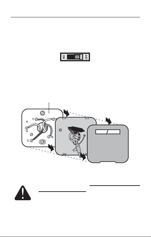
1) Turn power off at the heating/cooling system.
2) Remove old thermostat, but leave wallplate with
Remove Old Thermostat
wires attached.
Do not remove wallplate yet.
MERCURY NOTICE: Do not put your old
thermostat in the trash if it contains mercury in a
sealed tube. Contact your local waste
management authority for instructions regarding
recycling and proper disposal.
2.
3
Page 6
Quick Installation Guide
p
If any wires are not attached to your old thermostat or are
attached to a terminal marked C or C1, they will not be
connected to your new thermostat. Wrap the bare metal end
of each of these wires with electrical tape, so it cannot touch
and short other wires.
Identify Wires
Do not use
non-connected wires.
Do not use C or C1 wires
Identify and label each wire.
IGNORE WIRE COLORS:
Use terminal screw
designations to identify
wires.
Disconnect wires and remove the old wallplate only
after all wires are labeled. Wrap the wires around
a pencil to prevent them from falling though the
wall opening.
3.
4
Page 7
RCT8100 Programmable Thermostat
q
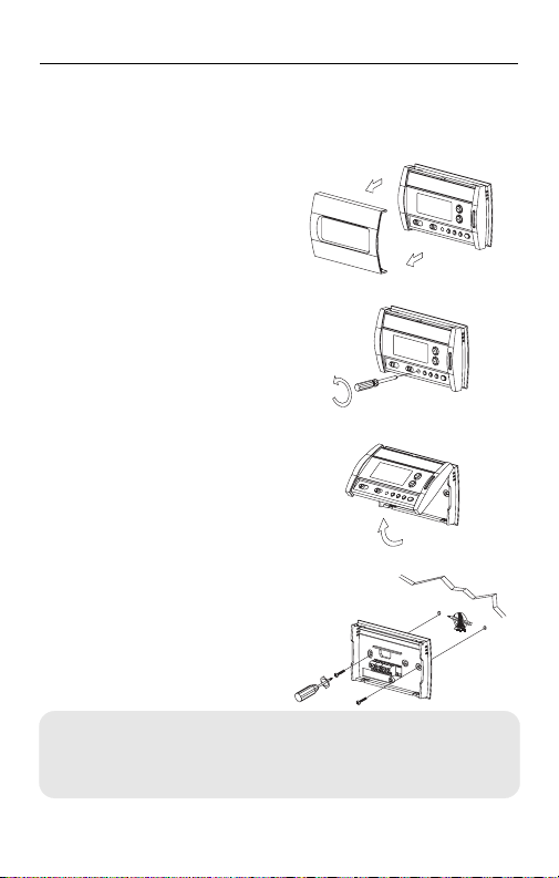
1) Remove coverplate.
2) Loosen screw (the
3) Remove thermostat.
4) Mark and drill
Mount New Wallplate
screw remains
captive on wallplate).
appropriate mounting
holes (or use existing
holes). Insert plastic
anchors. Pass wires
through opening of
wallplate and secure
Labels don’t match?
wallplate to the wall
If a wire does not match any terminal on the thermostat,
using provided
see next page.
screws.
4.
5
Page 8
Quick Installation Guide
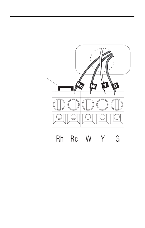
r
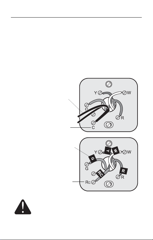
1) Match each labeled wire with the terminal having
2) Loosen the terminal screws using a screwdriver,
3) Push any excess wire back into the wall opening.
Connect Wires (typical wiring)
Remove jumper
if you have both
R and Rc wires.
the same letter.
insert the wires, then tighten the screws.
5.
6
Page 9
RCT8100 Programmable Thermostat
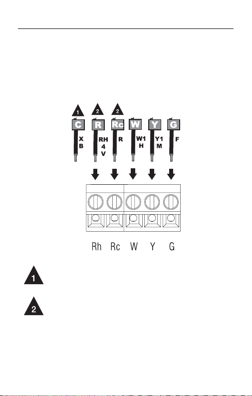
s
If a labeled wire does not match any terminal
designation, see diagram below.
Connect Wires (less common wiring)
Do not use C, X or B. Wrap bare end of wire
with electrical tape.
If wires are connected to both Rh and Rc
terminals, remove jumper (see previous
page).
7
Page 10

Quick Installation Guide
t
Set the Jumper J2, on the back of the thermostat, if
you have connected a wire to the G terminal.
Specify Furnace Type
Leave the jumper in this factory-set
HG
position if you have a gas or oil furnace.
Place the jumper to this position if you
HE
have an electric furnace.
J2 jumper
6.
8
Page 11

RCT8100 Programmable Thermostat
u
1) Pull out the battery cover.
2) Install the batteries as shown. Observe the
3) Reinstall the battery cover. You will hear a clicking
After the batteries are installed, the thermostat performs a series of tests for approximately 5 seconds.
Afterwards, the screen displays the actual temperature. It is normal that the displayed temperature be
higher than the ambient temperature if you are holding
the thermostat. The thermostat will display the ambient
temperature once it is installed on the wall. By default,
the setpoint is 70 °F (21 °C).
Install Batteries
polarity.
sound.
7.
9
Page 12

Quick Installation Guide
v
1) Mount the thermostat
2) Tighten the screw
3) Turn power back on
Install thermostat
on the wallplate.
and install the
coverplate.
at the heating/cooing
system.
8.
10
Page 13

RCT8100 Programmable Thermostat
w
System Setup
1) Press both and buttons simultaneously for 3
seconds to enter or exit the setup menu.
2) To advance to the next function, briefly press both
and buttons simultaneously.
3) To change the setting, press the or button.
9.
DISPLAY DESCRIPTION
Temperature display °C or °F
Time display 12 h or 24 h
Early Start
Heating cycles per hour
Cooling cycles per hour
1
Default settings are shown in bold and underlined.
2
See page 3 of Operating Manual.
3
Use the system switch to switch between the two parameters.
4
For optimal heating control, use the setting that matches your system as follows: 2=30 min (steam, gravity), 3=20 min (hot water,
90%+ high-efficiency furnace), 4=15 min (gas or oil), 5=12 min
(alternate setting for gas or oil), 6=10 min (electric).
5
The corresponding cooling cycle lengths are as follows: 2=30 min,
3=20 min, 4=15 min, 5=12 min, 6=10 min
2
3
3
11
OPTIONS
On or Off
2, 3, 4, 5 or 6
2, 3, 4, 5 or 6
1
4
5
Page 14

Quick Installation Guide
Automation and Control Systems
Honeywell International Inc.
1985 Douglas Drive North
Golden Valley, MN 55422
Honeywell Limited
35 Dynamic Drive
Scarborough, Ontario M1V 4Z9
http://DIYthermostats.honeywell.com
Printed in USA
69-2336ES-01 10-09
12
Page 15

Guía de instalación rápida
RCT8100
Termostato programable
Page 16

¿Necesita asistencia?
Estamos aquí para ayudarlo
Llame al 1-800-468-1502
Page 17

Termostato programable RCT8100
Instalación fácil
El nuevo termostato ha sido concebido para que su
instalación sea fácil. Sólo hay que seguir las
instrucciones de las páginas siguientes.
n Identificar el tipo de sistema.
o Retirar el viejo termostato.
p Identificar los cables.
q Montar la nueva placa mural.
r Conectar los cables.
s Cuando los cables no coinciden.
t Especificar el tipo de estufa.
u Instalar las pilas.
v Instalar el termostato.
w Configurar el sistema.
1
Page 18

Guía de instalación rápida
n
Este termostato es compatible con los siguientes
sistemas:
• Calefactor a gas, aceite o eléctrico
• Aire acondicionado central
• Sistema de agua caliente con o sin bomba
• Sistema de milivoltios
• Sistema de calefacción y aire acondicionado
Si no supiera cuál es su sistema o si tuviera otras
preguntas, llámenos sin cargo al 1-800-468-1502.
Este termostato no es compatible con las bombas
Identificar el tipo de sistema
central
de calor o los sistemas multietapas.
1.
2
Page 19

Termostato programable RCT8100
o
1) Cortar la electricidad del sistema de calefacción/
2) Retirar el viejo termostato pero dejar la placa
Retirar el viejo termostato
aire acondicionado.
mural con los cables conectados.
No retirar la placa mural todavía
ADVERTENCIA SOBRE EL MERCURIO:
no ponga su viejo termostato en la basura
contiene mercurio en un tubo sellado.
Comuníquese con la autoridad de gestión de
desechos local para saber cómo reciclarlo o
eliminarlo adecuadamente.
2.
si
3
Page 20

Guía de instalación rápida
p
Si en el viejo termostato hubiera cables no conectados o si
estuvieran fijados a un terminal marcado C o C1, estos
cables no se conectarán al nuevo termostato. Recubrir el
extremo de metal desnudo de cada uno con cinta aisladora
para que no puedan tocarse y producir un corto circuito.
Identificar los cables
No utilizar cables
no conectados
No utilizar cables C o C1
Identificar y etiquetar
cada cable.
IGNORAR LOS COLORES
DE LOS CABLES
usar las designaciones de
los tornillos terminales para
identificar los cables.
:
Desconectar los cables y retirar la vieja placa mural
sólo después de haber identificado y etiquetado los
cables. Enroscarlos en un lápiz para impedirles
caer dentro del agujero de la pared.
3.
4
Page 21

Termostato programable RCT8100
q
1) Retirar la placa de
2) Aflojar los tornillos
3) Retirar el termostato.
4) Marcar y perforar los
Instalar la nueva placa mural
cubierta.
(que quedarán
cautivos en la placa
mural).
agujeros de montaje
apropiados (o usar
los existentes).
Introducir los
anclajes plásticos.
Pasar los cables por
la apertura de la
placa mural y
¿Las etiquetas no coinciden?
asegurar la placa a la
Si un cable no corresponde a ningún terminal
pared con los
del termostato, referirse a la página siguiente.
tornillos provistos.
5
4.
Page 22

Guía de instalación rápida
r
1) Hacer coincidir cada cable etiquetado con el
2) Aflojar los cables del terminal con un
3) Empujar el exceso de cables en el agujero de la
Conectar los cables (conexión típica)
Retirar el puente
si hay cables R y
Rc.
terminal de la misma letra.
destornillador, luego ajustar los tornillos.
pared.
5.
6
Page 23

Termostato programable RCT8100
s
Si un cable etiquetado no coincide con la designación
de ningún terminal, referirse al diagrama siguiente:
Conectar los cables
No usar C, X o B. Enroscar el extremo
desnudo con cinta aisladora.
Si los cables están conectados con los
terminales Rh y Rc, retirar el puente (ver la
página previa).
(conexión menos común)
7
Page 24

Guía de instalación rápida
t
La posición del cable de puente J2, en la parte posterior del termostato, es importante si se conectó un
cable al terminal G.
Especificar el tipo de estufa
Dejar el puente en esta posición en el
HG
caso de un sistema de calefacción a gas
o a aceite.
Colocar el puente en esta posición en el
HE
caso de un sistema de calefacción eléctrico.
Puente J2
6.
8
Page 25

Termostato programable RCT8100
u
1) Retirar la cubierta de las pilas.
2) Instalar las pilas como se indica en el dibujo.
3) Reinstalar la cubierta de las pilas. Se escuchará
Luego de instalar las pilas, el termostato hace una
serie de pruebas por alrededor de 5 segundos.
Una vez terminadas las pruebas, la pantalla indicará
la temperatura actual. Es normal que la temperatura
indicada sea más elevada que la temperatura
ambiente si se tiene el termostato en la mano. El termostato indicará la temperatura ambiente cuando esté
instalado en la pared. El punto de ajuste de fábrica es
de 70°F (21°C).
Instalar las pilas
Respetar la polaridad.
un clic.
7.
9
Page 26

Guía de instalación rápida
v
1) Montar el termostato
2) Ajustar los tornillos e
3) Conectar el sistema
Instalar el termostato
en la placa mural.
instalar la placa de
cubierta.
de calefacción/aire
acondicionado a la
electricidad.
8.
10
Page 27

Termostato programable RCT8100
w
1) Presionar los botones y simultáneamente durante 3
Configuración del sistema
segundos para entrar o salir del menú de configuración.
2) Para avanzar a la siguiente función, presionar brevemente y
simultáneamente.
3) Para cambiar la configuración, presionar los botones o .
9.
PANTALLA DESCRIPCIÓN
Visualización de temperatura °C ó °F
Visualización de la hora 12 h ó 24 h
Encendido anticipado
Ciclos de calefacción/hora
Ciclos de enfriamiento/hora
1
Lo valores de fábrica están en negrita y subrayados.
2
Ver la página 3 del Manual de Uso.
3
Usar el conmutador del sistema para cambiar entre los dos parámetros.
4
Para un control óptimo de la calefacción, utilizar la configuración
correspondiente al sistema de la siguiente manera: 2=30 min. (vapor/
gravedad); 3=20 min. (agua caliente, 90%+ calefactor de alta eficacia);
4=15 min. (gas o aceite), 5=12 min. (ajuste alterno para gas o aceite);
6=10 min. (eléctrico).
5
La duración de los ciclos de aire acondicionado correspondientes son
los siguientes: 2=30 min., 3=20 min., 4=15 min., 5=12 min., 6=10 min.
2
3
3
OPCIONES
On ó Off
2, 3, 4, 5 ó 6
2, 3, 4, 5 ó 6
11
1
4
5
Page 28

Guía de instalación rápida
Sistemas para automatización y control
Honeywell International Inc.
1985 Douglas Drive North
Golden Valley, MN 55422
Honeywell Limited
35 Dynamic Drive
Scarborough, Ontario M1V 4Z9
http://DIYthermostats.honeywell.com
Impreso en EE.UU.
69-2336ES-01 10-09
12
 Loading...