

Page 1
T5+ Smart Thermostat
Programmable Thermostat
RCHT8610WF, RCHT8612WF
Product Data
For more information visit honeywellhome.com
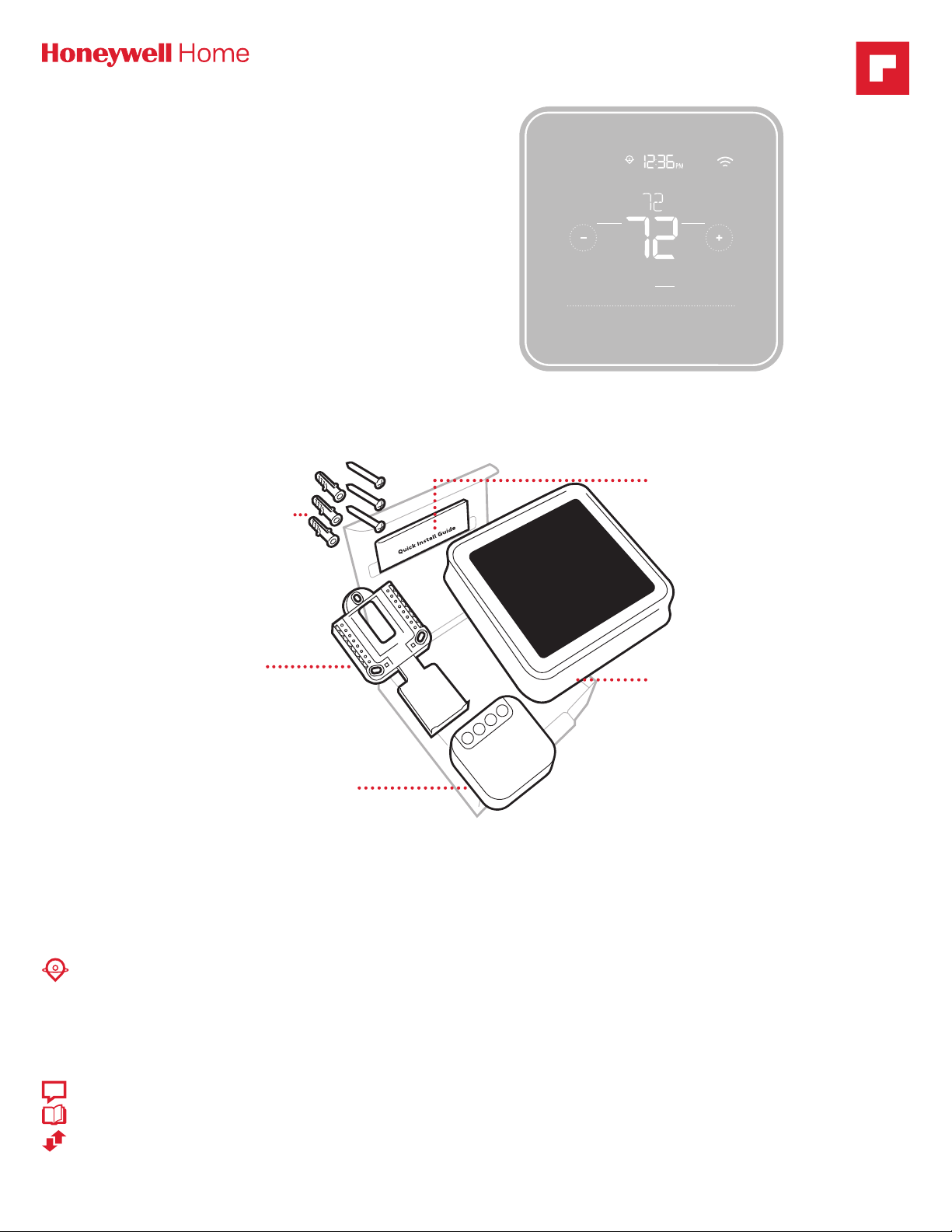
Included in your box
Screws and
anchors
Following Schedule
Mode
Heat
Wake
Mode
Away
Menu
Quick Install
Guide
Home
Fan
Auto
Sleep
Fan
UWP™
Mounting
System
(UWP)
CWire Power Adapter
(Located under thermostat.
Open end of box to remove it. T5
Smart Thermostat models that
don’t show a + on the package
after “T5” do not have the C-wire
adapter in the box.)
T5 Smart
Thermostat
Get the most from T5 Smart Thermostat
Multiple programming options that fit your lifestyle:
1. LocationBased scheduling – The thermostat uses your smartphone’s location to know when you’re away, and saves you energy. Through
geofence technology, it senses your return and helps make you comfortable upon arrival. You can always manually change your preset Home
and Away temperature either on the thermostat or on the Honeywell Home app.
2. Smart scheduling – Use a combination of geofencing and time scheduling to fit your busy, active lifestyle.
3. TimeBased scheduling – Program your thermostat for one week; each day (each day is a different schedule); MonFri, Sat, Sun; or MonFri,
SatSun. All days with four adjustable periods per day.
4. No scheduling – Control your comfort manually by adjusting temperature set points only.
Smart Alerts. Push notifications remind you of filter changes and warn you of extreme indoor temperatures.
!
Smart Response. Learns your heating and cooling system to deliver the optimal temperature at the right time.
Auto Change From Heat to Cool. Automatically determine if your home needs heating or cooling to provide maximum comfort.
Page 2
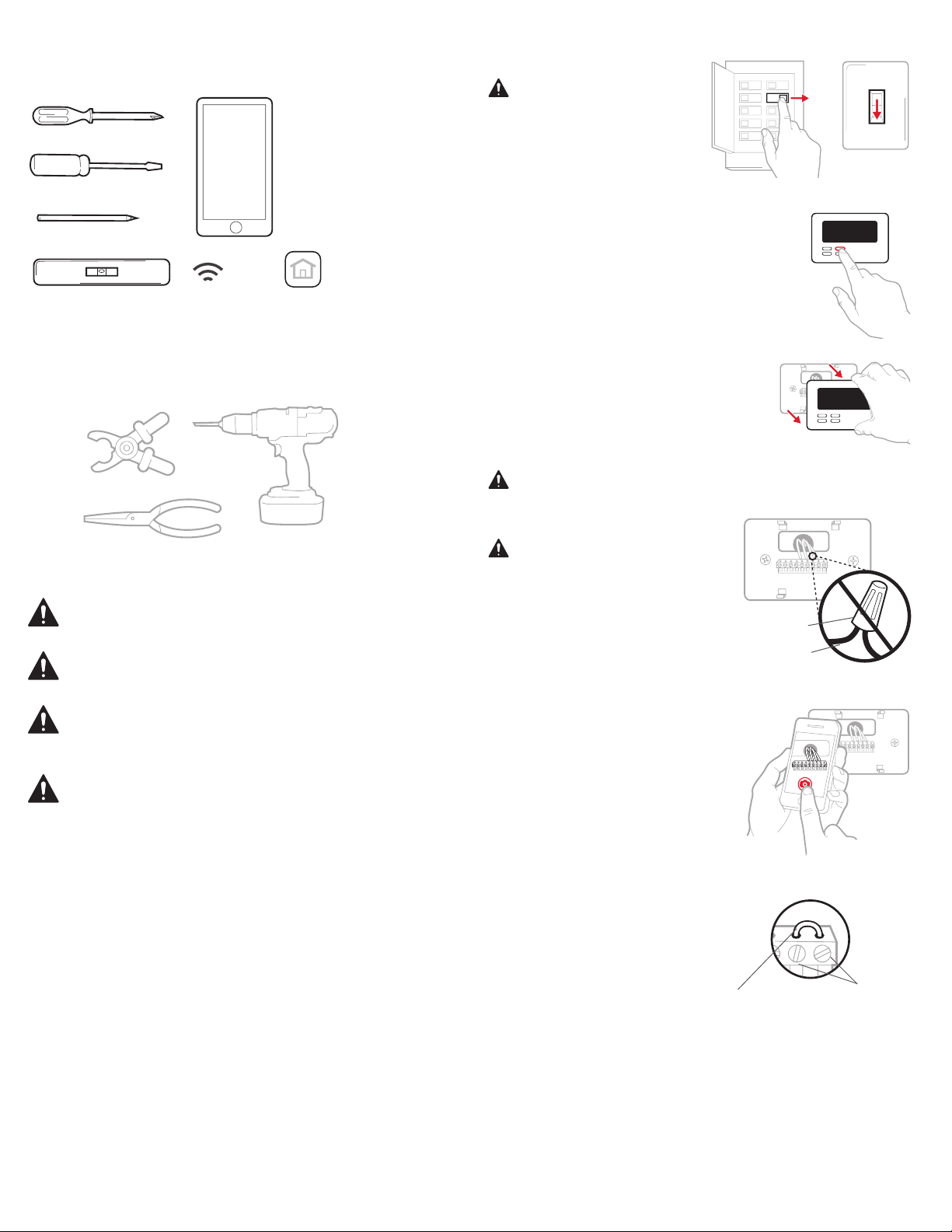
Small flat head scr
Phillips scr
Pencil
Le
OFF
Y
R RC
1/4” to 3/8”
Read and save these instructions.
Removing your old thermostat
Tools you will need
Smartphone
To install your
ewdriver
ewdriver
vel Home Wi-Fi
Password
thermostat and
photograph existing
wiring.
Honeywell Home app
To configure your
system and connect to
your smartphone.
You may need
Wire stripper
Needle-nose pliers Drill and
drill bit (7/32 in)
CAUTION: ELECTRICAL HAZARD
Can cause electrical shock or equipment damage. Disconnect power before beginning
installation.
CAUT ION: EQUIPMENT DAMAGE HAZARD
Compressor protection is bypassed during testing. To prevent equipment damage,
avoid cycling the compressor quickly.
CAUTION: MERCURY NOTICE
If this product is replacing a control that contains mercury in a sealed tube, do not
place the old control in the trash. Contact your local waste management authority for
instructions regarding recycling and proper disposal.
REQUIRED: 24 VAC POWER (“C” WIRE)
CWire Power Adapter Included to provide power if needed.
Compatibility
• Compatible with most heating, cooling, and heat pump systems
• Required: 24 VAC power (“C” wire). CWire Power Adapter Included to
provide power if needed
• Does not work with electric baseboard heat (120240V)
• Does not work with millivolt systems
• Does not support input (S terminals) for indoor and outdoor sensors
• Does not support relay (U terminals) for ventilation
• Android or iOS smartphone, tablet, or device
For help, contact
WEB honeywellhome.com/support
PHONE 18006333991
SOCIAL Twitter: @Honeywell_Home, Facebook: Honeywell Home
1 Turn power OFF
To protect yourself and your
equipment, Turn off the power
at the breaker box or switch that
controls your heating/cooling
system.
2 Check that your system is off
Change the temperature on
your old thermostat. If you don’t
hear the system turn on within 5
minutes, the power
is off.
Note: If you have a digital thermostat that has a blank display, skip
this step.
3 Remove your old thermostat from
the wall plate
On most thermostats, you can take
off the thermostat by grasping and
gently pulling. Some thermostats
may have screws, buttons, or
clasps.
Do not remove any wires from
your thermostat at this time!
4 Make sure there are no
120/240V wires
Do you have thick black wires
with wire nuts?
Is your thermostat 120V or
higher?
If you answered yes to either of
these questions, you have a line
voltage system and the thermostat
will not work.
If you are unsure visit:
honeywellhome.com/support
5 Take a picture of how your wiring
looks right now
Be sure to include the letters
next to the terminals where the
wires are inserted. This will be a
helpful reference when wiring your
thermostat.
Tip: If the color of your wires has
faded or if 2 terminals have the
same wire color, use the wire
labels provided in the package to
label each wire.
6 Remove any jumpers
A jumper connects one terminal to
another terminal. It may look like
a small staple or even a colored
wire and must be removed before
continuing. Use a screwdriver to
release wires from terminals.
The thermostat does not
need jumpers.
OFF
ON
OFF
Switch
Breaker box
75
Wire nut
Thick black wire
Ter mina ls
Example of
a jumper
2
Page 3
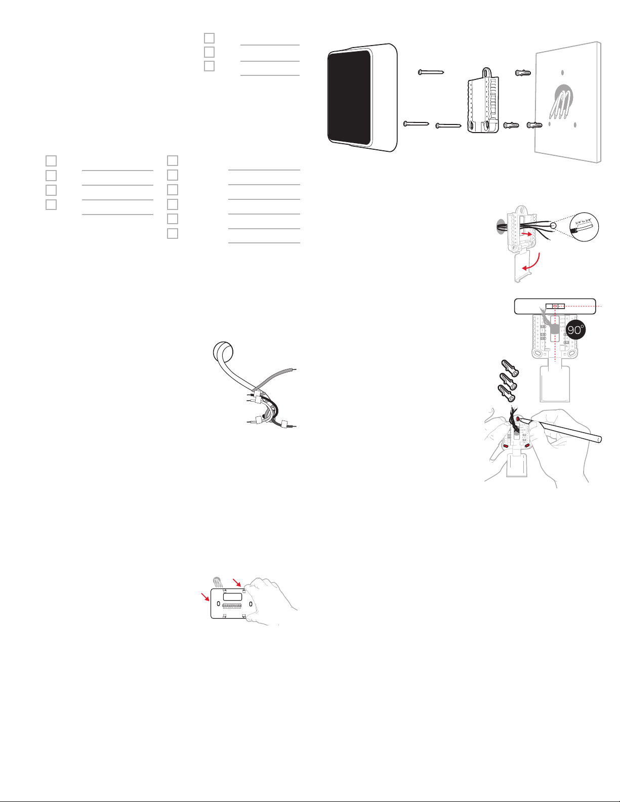
7 Record if you have wires in the
following terminals
Do not include jumpers as a part
of your count. The thermostat
does not need jumpers.
8 Write down the color of the wires
Check mark the wires that are connected to terminals. Next to the
check mark, write down the color of the wire. Do not include jumpers
as a part of your count.
Check all that apply (Not all will apply):
Terminal Wire Color
Y
Y2
G
C
Requir ed (see step 9)
S and U terminals are not supported with this thermostat.
If there are wires in terminals that are not listed, you will need
additional wiring support. Visit honeywellhome.com/support to
find out if the thermostat will work for you.
9 Do you see a wire connected to the C terminal?
If yes, skip to step 10.
If you do not see a C wire, proceed with the options below:
Option A - Finding the CWire:
There might be an extra wire pushed into
the wall or wrapped around the wire bundle. Gently pull the wire bundle out of the
wall to check for unused wires.
If you have an unused wire, connect that
wire to the C terminal on your new thermostat in step 13.
Connect the other end of the unused wire
to the C terminal on your heating/cooling
system (or the zone panel if your home
uses more than one thermostat to control temperature). Be sure any
other wire(s) connected to the C terminal stay securely connected
when you re-tighten the terminal.
Not all heating/cooling equipment use the C label for the 24 VAC
common wire. If your heating/cooling equipment does not have a C
terminal , check the system manual or contact the manufacturer to
find out which terminal is the 24 VAC common.
Complete installation by following the remaining steps in this guide.
Option B - Using the CWire Power Adapter:
If you do not have an unused wire in the wall , see the C Wire Adapter
Installation Guide included in the box. Open the top or bot tom flap
of the box to locate the C Wire Adapter.
10 Disconnect the wires and remove the
old wall plate
Use a screwdriver to release wires from
terminals.
Tip: To prevent wires from falling back
into the wall, wrap the wires around a
pencil.
Terminal Wire Color
R
Rh
Rc
Terminal Wire Color
A or L/A
O/B
W2 or AUX
E
W
K
Installing your T5 Smart Thermostat
T5 Smart
Thermostat
11 Bundle and insert wires through
the UWP
Pull open the UWP and insert the
bundle of wires through the back
of the UWP.
Make sure at least 1/4-inch of
each wire is exposed for easy
insertion into the wire terminals.
12 Insert the wall anchors
It is recommended that you use
the wall anchors included in the
box to mount your thermostat.
You can use the UWP to mark
where you want to place the wall
anchors.
a) Level the wall plate.
b) Mark the location of the wall
anchors using a pencil.
c) Drill the holes.
d) Insert wall anchors.
e) Make sure anchors are flush
with wall.
Tip: Use a 7/32 drill bit.
Screws
UWP
Mounting
System
Anchors Wall
3
Page 4
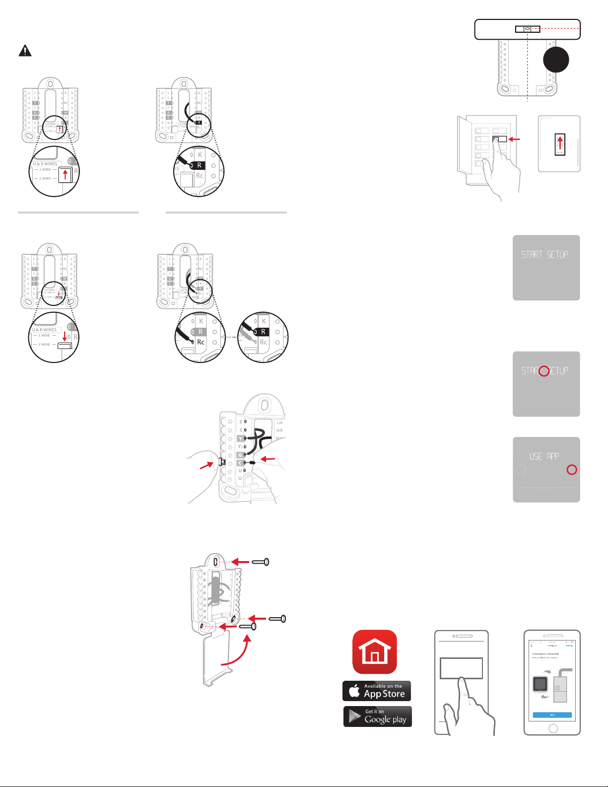
13 Set R-switch position and insert R-wire or wires
ON
Set the R-switch up or down based on your wiring notes in Step 7.
Insert wires into the inner holes of the terminal s on the UWP. The
tabs will stay down once the wire is inserted.
If you have 1 R-wire (R, Rh, or Rc)
16 Attach your thermostat
Align the thermostat onto the
UWP and firmly snap it into place.
o
90
1. Set
R-switch to
the up
position.
or
If you have 2 R-wires (R or Rh, and Rc)
1. Set
R-switch
to the down
position.
2. Insert your
R-wire (R, Rh
or Rc) into
R-terminal.
2. Insert your
Rc wire into
Rc-terminal.
3. Insert your
R or Rh
wire into
RTerminal.
17 Turn your power ON
Turn on the power at the breaker
box or switch that controls the
heating/ cooling system.
Breaker box
ON
18 Return to the thermostat
Return to the thermostat. Confirm
the screen shows S TART SETUP.
If it does, continue to “Setup with
Honeywell Home App” below.
If your thermostat does not show
START SE TUP, please contact
Resideo support.
Setup with Honeywell Home App
1 Start Setup with the app
Tou ch STAR T SET UP on thermostat.
ON
OFF
Switch
14 Connect remaining wires from
Step 8
Tip: Do not mount the UWP to the
wall prior to connecting the wires.
Depress the tabs to put the wires
into the inner holes of their corresponding terminals on the UWP
(one wire per terminal) until it is
firmly in place.
Gently tug on the wires to verify
they are secure.
Tip: If you need to release the
wires again, push down the
terminal tabs on the sides of the
UWP.
15 Mount the UWP and close the
door
Mount the UWP using the
provided screws. Install all three
screws for a secure fit on your
wall. Close the door after you’re
finished.
This wiring is just an example,
actual wiring may vary.
Use 3x
supplied
screws #8
11/2”
2 Select to setup with the app
Touch Yes on the USE APP screen.
No
Back
3 Your thermostat is now ready to be configured using the
Honeywell Home app
a) Download the “Honeywell Home” app from the App store or
Google play.
b) Open the Honeywell Home app. Your thermostat should appear
under Thermostat Found. Tap SET UP NOW as shown below to
continue. If your thermostat doesn’t appear, create an account
(if necessary), or sign in to your Honeywell Home account. Then
select the T5 Smart Thermostat to install.
c) The Honeywell Home app will walk you through the rest of setup.
A B
Thermostat Found:
SET UP NOW
C
Yes
4
Page 5

How to use your Honeywell Home App
Thermostat
MY HOME
Access the
menu
72˚
FOLLOWING SCHEDULE
Set desired
72˚
temperature
Manual Setup
If your WiFi net work is not working,
you can alternatively setup your thermostat manually and connect your
phone later.
1 Start manual setup
Touch START SETUP to begin.
2 Select manual setup
On the USE APP screen, touch No.
Select Fan mode
Auto/On/Circulate.
Select System
mode Auto/Heat/
Cool/Off/EM Heat
SCHEDULEFANMODE
Schedule your home
comfort
Interested in more Resideo products? Visit honeywellhome.com to learn
about all available products connected by the Honey well Home app.
App is re gularly enh anced and may cha nge.
How to use your T5 Smart Thermostat
Desired temperature
Displays desired
indoor temperature.
Indoor Temperature
Displays current
indoor temperature.
Menu
Fan
Auto
Mode
Mode
Heat
Adjust temperature
Touch + or - to set
your desired indoor
temperature.
Fan
3 Navigate and edit setup options
Use or to navigate through
all the setup options. To see a list
of all setup options, go to pages
67.
To edit an option value, touch Edit
or touch text area.
The value is now blinking. Use
or to select the correct value.
Tou ch Done or touch tex t area once
the correct value is selected.
4 Finish Setup
Touch until you see Finish
Setup. Touch Select or touch text
area.
5 Setup WiFi
At the end of setup process you
will be prompted to SETUP WIFI. If
your WiFi is still not working, you
have to manually set the time and
date. Select No on the SETUP WIFI
screen.
No
No
Back
Yes
Edit
Select
Yes
Mode
Select System
mode Auto/Heat/
Cool /Off/EM Heat
(emergency heat).
The screen will wake up by touching the
Menu
Contains features:
schedule, screen
Fan
Select Fan mode
Auto/On/Circulate.
lock, ventilation, WiFi, clean screen, and
other thermostat
settings.
center area of displayed temperature.
6 Set time and date
Set daylight saving time if you are
in an area that follows daylight
saving time. Set date, clock format
and time on the next screens.
7 Your thermostat is now setup
Refer to page 5 for more
information about basic operation.
5
No
Back
Yes
Page 6

Equipment Setup Options
Note: ISU options available may vary upon the thermostat model and equipment setup.
# ISU ISU Name ISU Options (defaults in bold) Notes
120 Schedule Type No Schedule
MOSU = Every day the same
MOFR, SA, SU = 511 schedule
MO-FR, SA-SU = 5-2 schedule
Each Day = Every day individual
125 Temp Scale Fahrenheit, Celsius
130 Outdoor Temp No, Internet Select outdoor temperature data source. This ISU automatically defaults to Internet when
You can change default MOFR, SASU schedule here. To edit periods during days, temperature setpoints, or to turn Schedule On/Off, from the home screen, go to MENU/SCHEDULE.
registered to the Honey well Home app. An outdoor temperature is required to set the following
ISUs: ISU 355 Compressor Lockout, ISU 356 Aux Heat Lockout.
200 System Typ e Conventional Forced Air
Heat Pump
Boiler
Cool Only
205 Equipment Type Conventional Forced Air Heat:
Standard Gas (STD GA S), High Efficiency Gas
(EFF GAS), Oil, Electric, Fan Coil*
Heat Pump:
Air To Air, Geothermal
Boiler:
Hot Water, Steam
218 Reversing Valve 0/B on Cool, 0/B on Heat This ISU is only displayed if ISU 200 is set to Heat Pump. Select whether reversing valve O/B
220 Cool Stages
(#200=Conv./
200=HP)
221 Heat Stages/
Aux/E Stages
(#200=Conv./
200=HP)
230 Fan Control Equipment, Thermostat This ISU is only displayed if ISU 205 is set to Electric Forced Air or Fan Coil .
300 Auto Changeover On, Off OFF: The user must select heating or cooling as needed to maintain the desired
303 Auto Differential 0 °F to 5 °F or 0.0 °C to 2.5 °C Differential is the minimum number of degrees rise or fall required during off cycle to switch
355 Balance Point
(Compressor
Lockout)
356 Aux Heat Lock
Out (Aux Heat
Outdoor Lockout)
365 Cool 1 CPH
(Cooling cycle
rate stage 1)
366 Cool 2 CPH
(Cooling cycle
rate stage 2)
0, 1, 2
Heat Stages: 0, 1, 2
AUX/E Stages: 0, 1
Off, 5 °F to 60 °F (in 5 °F increments) or 15.0 °C
to 15.5 °C (in 2.5 °C or 3.0 °C increments)
Off, 5 °F to 65 °F (in 5 °F increments) or
15.0 °C to 18.5 °C (in 2.5 °C or 3.0 °C increments)
1 - 6 CPH (3 CPH) This ISU is only displayed when Cool /Compressor Stages is set to 1 or more stages. Cycle rate
1 - 6 CPH (3 CPH) This ISU is only displayed when Cool /Compressor Stages is set to 2.
Basic selection of system your thermostat will control.
This option selects the equipment type your thermostat will control. Note: This option is NOT
displayed if ISU 200 is set to Cool Only.
* Fan coil setting is for a residential application with a hot water coil in an air-handler.
should energize on cool or on heat
Maximum of 2 Heat Stages for conventional systems. Maximum of 1 Aux/E stages for heat
pump systems.
indoor temperature.
ON (Automatic): On (enabled) Allows user to select Auto Changeover as one of the system
modes from the home screen. In auto mode, the thermostat can control either heating or cooling to maintain the desired indoor temperature.
from the last active mode (heat or cool) to the opposite mode when the thermostat is in
auto-changeover. Differential is NOT deadband. The deadband temperature between when
heating (or cooling) cycles on and cycles off to maintain setpoint is not adjustable. The T5
thermostat uses an algorithm that fixes deadband at 0 °F.
Compressor Lockout requires an outdoor temperature. Set Compressor Lockout to the
temperature below which it is inefficient to run the heat pump. When outside temperature is
below this setting, thermostat will lockout heat pump and run Aux Heat only. This ISU is only
displayed if ISU 130 = Internet, ISU 200 is set to Heat Pump, ISU 221 Aux /E stages = 1,.
Aux Heat Lockout requires an outdoor temperature. Set Aux Heat Lockout to optimize energy
bills and to not allow it to run the more expensive Aux Heat source above cer tain outdoor temperature limit. This ISU is only displayed if ISU 200 is set to Heat Pump, AND if ISU 221 Aux/E
stages = 1.
limits the maximum number of times the system can cycle in a 1 hour period measured at a
50% load. For example, when set to 3 CPH, at a 50% load, the most the system will cycle is 3
times per hour (10 minutes on, 10 minutes off). The system cycles less often when load conditions are less than or greater than a 50% load.
6
Page 7

# ISU ISU Name ISU Options (defaults in bold) Notes
370 Heat 1 CPH
(Heating cycle
rate stage 1)
1 - 12 CPH This ISU is only displayed when Heat Stages is set to 1 stage or more stages. Cycle rate limits
the maximum number of times the system can cycle in a 1 hour period measured at a 50%
load. For example, when set to 3 CPH, at a 50% load, the most the system will cycle is 3 times
per hour (10 minutes on, 10 minutes off). The system cycles less of ten when load conditions
are less than or greater than a 50% load. The recommended (default) cycle rate settings are
below for each heating equipment type:
Standard Efficiency Gas Forced Air = 5 CPH; High Efficiency Gas Forced Air = 3 CPH; Oil
Forced Air = 5 CPH; Electric Forced Air = 9 CPH; Fan Coil = 3 CPH; Hot Water Radiant Heat
= 3 CPH; Steam = 1 CPH.
371 Heat 2 CPH
(Heating cycle
rate stage 2)
1 - 12 CPH This ISU is only displayed when Heat Stages is set to 2 stages. The recommended (default)
cycle rate settings are below for each heating equipment type:
Standard Efficiency Gas Forced Air = 5 CPH; High Efficiency Gas Forced Air = 3 CPH; Oil
Forced Air = 5 CPH; Electric Forced Air = 9 CPH; Fan Coil = 3 CPH; Hot Water Radiant Heat
= 3 CPH; Steam = 1 CPH.
375 Aux Heat CPH
(Heating cycle
rate Auxiliary
Heat)
1 - 12 CPH This ISU is only displayed when ISU 200 = Heat Pump and ISU 221=1. It is only displayed when
Auxiliar y Heat is configured. The recommended cycle rate settings are below for each heating
equipment type:
Standard Efficiency Gas Forced Air = 5 CPH; High Efficiency Gas Forced Air = 3 CPH; Oil
Forced Air = 5 CPH; Electric Forced Air = 9 CPH.
425 Smart Response On, Off Smart Response is a comfort setting. Heating or cooling equipment will turn on earlier, ensur-
ing the indoor temperature will match the setpoint at the scheduled time.
429 Max Cool
Temperature
430 Min Cool
Temperature
431 Max Heat
Temperature
432 Min Heat
Temperature
from Min. Cool Temp. to 99 °F or to 37.0 °C (90 °F
or 32 °C)
from 50 °F or 10.0 °C to Max. Cool Temp. (50 °F
or 10 °C)
from Min. Heat Temp. to 90 °F or to 32.0 °C (90 °F
or 32 °C)
from 40 °F or 4.4 °C to Max. Heat Temp. (50 °F
or 10 °C)
The user cannot set the cooling temperature above this level.
The user cannot set the cooling temperature below this level.
The user cannot set the heating temperature above this level.
The user cannot set the heating temperature below this level.
702 Air Filters 0 - 2 This ISU refers to the number of air filters in the system.
711 Air Filter 1
Reminder
Off
10, 20, 30, 45, 60, 90, 120, 150 Run Time Days
Choose either calendar or equipment run time-based reminder.
30, 45, 60, 75 Days
3, 4, 5, 6, 9, 12, 15 Months
712 Air Filter 2
Reminder
Off
10, 20, 30, 45, 60, 90, 120, 150 Run Time Days
Choose either calendar or equipment run time-based reminder.
30, 45, 60, 75 Days
3, 4, 5, 6, 9, 12, 15 Months
810 Hum Pad
Reminder
921 Dehum Filter
Reminder
Off
6, 12 Calendar Months
Off
30, 60 Calendar Days
3 - 12 Calendar Months (in 1 month increments)
1018 Vent Filter
Off, 3, 6, 9, 12 months
Reminder
1100 UV Devices 0 - 2 Some systems may have two UV devices, one for the ACoil and another for Air Treatment. A
replacement reminder can be setup for each one separately.
1105 UV Bulb 1
Off, 6, 12, 24 months
Reminder
1106 UV Bulb 2
Off, 6, 12, 24 months
Reminder
1401 Idle Brightness 0= Off, 0 - 5 Adjust brightness of an inactive backlight (idle screen) from default 0 (backlight off) to 5
(maximum
brightness).
1410 Clock Format 12 hour, 24 h our
1415 Daylight Saving On, Off Set to Off in areas that do not follow Daylight Saving Time.
7
Page 8

Frequently Asked Questions
Will the T5 Smart Thermostat still work if WiFi connection is lost?
Yes, the temperature can be adjusted directly at the thermostat. However, some features, including geofencing, are managed only
through the Honeywell Home app and will not function while the connection is down. The thermostat will automatically reconnect to WiFi once the network is restored.
The T5 Smart Thermostat is not finding the in home WiFi network.
The thermostat operates in the 2.4GHz range. That may be why the thermostat does not see the network but the smartphone, which
operates in both the 2.4 and 5.0 GHz range, sees the network. Most routers will broadcast two networks, one SSID on the 5.0 GHz radio
and one SSID on the 2.4 GHz radio.
A change was made on the Honeywell Home app but it has not shown up on the T5 Smart Thermostat.
There may be a short delay after making temperature and setting changes in the Honeywell Home app.
Can there be multiple users for geofencing?
Yes, there can be multiple users. Geofencing will trigger based on the last person to leave and the first person to return. To properly use
geofencing with multiple users:
• Each user needs to create their own account.
• Each user should use their login ID and password across his or her devices, including smartphones and tablets.
• No two users should share the same account.
How are multiple users set up with thermostat?
Access can be given to any or all thermostat locations through the Honeywell Home app. Start by touching the three-line menu icon in
the upper left-hand corner of the home screen. Select Manage Users and touch Add User located at the bottom of the screen. Type in the
email address of the person to be invited. If they have an account set up, the location will be automatically added to their account. If they
don’t have an account, they will receive an email invitation prompting them to download the Honeywell Home app and create their own
account.
Note: All individuals with access to a thermostat share the same user privileges. Users added will be able to change the thermostat’s
settings, as well as add or delete other users.
Is there a way to extend the signal strength?
The range or distance of the WiFi signal is determined by the router. Check the router’s manual for additional information.
There is an alert that says WiFi Signal Lost. What does that mean?
The WiFi signal to the thermostat has been lost. Wait for the thermostat to reconnect or select a new network within the Honeywell
Home app configuration menu. If the thermostat is unable to reconnect, you will need to troubleshoot the router to determine the cause.
Why is the thermostat showing up as offline (strike-through WiFi icon) on top of right corner of thermostat display?
If the thermostat displays a strike-through WiFi icon on its screen or shows up as offline on the Honeywell Home app, it has lost
connection to the network. Make sure the router is powered and broadcasting. The home’s WiFi network may need to be reset by power
cycling the router. Consult the router’s instruction manual for directions on power cycling. When the network has been restored, the
thermostat will automatically reconnect.
An activation email hasn’t been received.
An email will be sent from connectedHome@alarmnet.com. An activation email is needed to complete the account setup. If an activation
email is not received after five minutes, check the Spam folder of the email account.
If you do not find it in the Spam folder, click on the Resend button and the activation email will be resent. If you still do not receive your
activation email, please contact the Technical Support team at 18006333991 for help.
Regulatory information
FCC REGULATIONS
47 CFR § 15.19 (a)(3)
This device complies with part 15 of the FCC Rules. Operation is
subject to the following two conditions:
1. This device may not cause harmful interference, and
2. This device must accept any interference received, including
interference that may cause undesired operation.
47 CFR § 15.21 (USA only)
Changes or modifications not expressly approved by the party
responsible for compliance could void the user’s authority to
operate the equipment.
47 CFR § 15.105 (b)
See https://customer.resideo.com/enUS/support/residential/
codes-and-standards/FCC15105/Pages/default.aspx for
additional FCC information for this product.
IC REGULATIONS
RSSGEN
This device contains licence-exempt transmitter(s)/receiver(s)
that comply with Innovation, Science and Economic Development
Canada’s licence-exempt RSS(s). Operation is subject to the
following two conditions:
1. This device may not cause interference.
2. This device must accept any interference, including
interference that may cause undesired operation of the device.
8
Page 9

Apple® HomeKit™ Setup Code
The T5 Smart supports Apple HomeKit. When prompted by the
Honeywell Home app, scan the code on the back cover of the
guide included with your T5 Smart thermostat.
2Year Limited Warranty
For Warranty information go to honeywellhome.com
9
Page 10

10
Page 11

11
Page 12

Resi deo Inc., 1 985 Dougla s Drive Nor th
33-00474-01
Golde n Valley, MN 55 422
www.resideo.com
©2019 Resideo Technologies, Inc.
This product is manufactured by Resideo Technologies, Inc., Golden Valley, MN, 1-800-633- 3991.
The Honeywell Home trademark is used under license from Honeywell International Inc. All rights reserved.
33-00474-01 M.S. 4-19 | Printed in United States
Wi-Fi® is a registered trademark of
Wi-Fi Alliance®
 Loading...