

Honeywell Rapid Eye LT Installation Manual

Rapid Eye™ LT
Digital Video Recorder
Installation Guide
Document 800-07766V1 – Rev A – 02/11


Installation Guide

Revisions
Issue Date Revisions
A 11/10 New document, based on 800-02607V3, rev A for Rapid Eye Multi-Media, V9.
V1 Rev A 02/11 Revision of 800-07766, Rev A. No major content changes. Changes include PAL RE LT
units no longer supporting the internal modem.
4

About This Document
This document introduces the Rapid Eye™ Multi-Media LT Digital Video Recorder (DVR). It
covers how to install and prepare the Rapid Eye Multi-Media LT DVR for use.
This document is intended for installers.
Overview of Contents
Rapid Eye™ LT DVR Installation Guide
This document contains the following chapters and appendixes:
• Chapter 1, Introduction, introduces you to your Rapid Eye Multi-Media LT unit.
• Chapter 2, Installation, provides procedures for installing the Multi-Media LT unit, its
components, and configuring your network settings.
• Chapter 3, Quick Test for Remote Video, describes a quick test to confirm that all the
Rapid Eye hardware and software is working properly.
• Chapter 4, Audio, identifies procedures to check for audio interference and to monitor
and record audio data.
• Chapter 5, Site Hardware, shows how to add hardware to a Multi-Media LT DVR and
then use the software to configure the hardware.
• Appendix A, Frequently Asked Questions, reports solutions to frequently asked
questions.
• Appendix B, Cabling, offers cabling options and length limits.
• Appendix C, Horizontal and Vertical Unit Installations, describes the procedures
needed to install the unit in a vertical orientation. The unit comes ready to install
horizontally.
• Appendix D, Site Information Checklists, presents checklists that may be useful to the
installers.
Document 800-07766V1 Rev A 5
02/11
Cautions and Warnings
Caution This equipment is ONLY designed to be mounted and operated in a
horizontal position.
Caution Do NOT remove or defeat the ground pin of the 3-prong electrical
plug.
Caution The power cord is the disconnect device. Remove the appliance
coupler connector to disconnect the equipment.
Caution Equipment shall be connected to a grounded (earthed) outlet.
Installation and servicing should be performed only by qualified and experienced
technicians, to conform to all local codes and to maintain your warranty.
WEEE (Waste Electrical and Electronic Equipment). Correct disposal of this
product (applicable in the European Union and other European countries with
separate collection systems). This product should be disposed of, at the end of
its useful life, as per applicable local laws, regulations, and procedures.
FCC Compliance Statement
Information to the User: This equipment has been tested and found to comply with the
limits for a Class A digital device. Pursuant to Part 15 of the FCC Rules, these limits are
designed to provide reasonable protection against harmful interference in a commercial
environment. This equipment generates, uses, and can radiate radio frequency energy and,
6

FCC Part 68
Rapid Eye™ LT DVR Installation Guide
if not installed and used in accordance with the instruction manual, may cause harmful
interference to radio communications. Operation of this equipment in a residential area is
likely to cause harmful interference in which case the user will be required to correct the
interference at his own expense.
Caution Changes or modifications not expressly approved by the party
responsible for compliance could void the user’s authority to
operate the equipment.
This equipment complies with Part 68 of the FCC rules. You must provide this information
to the telephone company when requested:
Registration number: 1MXMM00B56MA
REN: 0.8
This equipment uses a USOC jack: RJ11.
Industry Canada
This equipment may not be used on telephone-company-provided coin service.
Connection to party lines is subject to state tariffs.
This Class A digital apparatus complies with Canadian ICES-003.
Cet appareil numérique de classe A est conforme à la norme NMB-003 du Canada.
NOTICE: This equipment meets telecommunications network protective, operational and
safety requirements as prescribed in the appropriate Terminal Equipment Technical
Requirements document(s). This is confirmed by marking the equipment with the Industry
Canada certification number. The Department does not guarantee the equipment will
operate to the user's satisfaction.
Before installing this equipment, users should ensure that it is permissible to be connected
to the facilities of the local telecommunications company. The equipment must also be
installed using an acceptable method of connection. The customer should be aware that
compliance with the above conditions may not prevent degradation of service in some
situations.
Repairs to certified equipment should be coordinated by a representative designated by the
supplier. Repair or alteration made by the user to this equipment, or equipment
malfunctions, may make the telecommunications company request the user disconnect the
equipment.
Users should ensure for their protection that the electrical ground connections of the power
utility, telephone lines and internal metallic water pipe if present, are connected together.
This precaution may be particularly important in rural areas.
Document 800-07766V1 Rev A 7
02/11

Caution Users should not attempt to make such connections themselves
but should contact the appropriate electric inspection authority, or
electrician, as appropriate.
Manufacturer’s Declaration of Conformance
Honeywell Video declares that HREwRxxyzzz Rapid Eye Multi-Media LT remote units are in
conformity with Council Directives:
2004/108/EC (EMC), 2006/95/EC (LVD).
These EuroNorms and harmonized standards were applied:
• EN55022: 2006 + A1: 2007, Information Technology Equipment. Radio disturbance
characteristics limits and methods of measurement;
• EN50130-4: 1995 + A1: 1998 + A2: 2002, Alarm/security immunity requirements;
• EN60950-1: A11: 2006, Safety of ITE;
• EN61000-3-2: 2006 + A2: 2009, Power-line Harmonics;
• EN61000-3-3: 2008, Flicker.
Specification Summary
Specification Description
Operating
Environment
Temperature 40°F to 104°F (+5°C to +40°C), EN 50130-5 Environmental Class 1
Power 100 - 240 V~, 50 / 60 Hz, auto-ranging
Heat dissipation 410 BTU/hr
Interface
Cable requirement Cables included with the unit are listed in Table 2-1, on page 23.
Network access Auto-sensing for 100BaseT or 10BaseT. LAN/WAN use through
Modem (North
America only)
Other connectors: BNC (video IN/OUT, public display), PC mouse,
PC keyboard, RJ-11 (dial-up), RJ-45 (LAN), USB, audio card
(OUT/MIC IN), screw terminal connectors (ALARM & CONTROL),
and custom RJ-45 (serial ports).
DSL or cable.
Internal. Programmable. Complies with FCC (ACTA) Part 68,
Industry Canada, TBR-21 - Public Switched Telephone Network
(PSTN) and Private Branch Exchange (PBX).
8

Rapid Eye™ LT DVR Installation Guide
Specification Description (cont’d)
Local video output Television monitor, for public display.
VGA monitor, for operation and/or public display.
DVD-RW drive For unit upgrade and/or duplicating and distributing video clips.
Standards
UL 60950-1 ETL listed for US and Canada (cETLus)
EN 60950-1 CE report
EN 50130-4 Security system immunity requirements (UPS required)
EN 61000-6-3 RF emissions, residential environments (EN 55022 Class A)
Caution This equipment shall be connected to an earthed mains outlet.
Warranty and Service
Subject to the terms and conditions listed on the Product warranty, during the warranty
period Honeywell will repair or replace, at its sole option, free of charge, any defective
products returned prepaid.
In the event you have a problem with any Honeywell product, please call Customer Service
at 1.800.796.CCTV for assistance or to request a Return Merchandise Authorization
(RMA) number.
Be sure to have the model number, serial number, and the nature of the problem available
for the technical service representative.
Prior authorization must be obtained for all returns, exchanges, or credits. Items shipped
to Honeywell without a clearly identified Return Merchandise Authorization (RMA)
number may be refused.
Document 800-07766V1 Rev A 9
02/11

Related Documents
This document is a necessary prerequisite for understanding the Honeywell Rapid Eye™
Multi-Media LT DVR. For more information, please refer to the documents listed in the table
below (included on the Documentation CD that came with your Rapid Eye LT unit). Find the
latest versions of these documents on the Honeywell Video website (see
www.honeywellvideo.com/products/recorders/).
Document title Description
Rapid Eye™ Multi-Media Digital
Video Recorder System
Administrator Guide
Rapid Eye™ Multi-Media Digital
Video Recorder Remote View
Operator Guide
Rapid Eye™ Multi-Media Digital
Video Recorder System Common
Operator Guide
Rapid Eye™ Multi-Media LT Quick
Start Guide
This guide is written for system administrators of Rapid Eye Multi-Media
DVRs. This guide covers setting up and managing single and multiple DVR
systems, both locally and remotely.
This guide is written for remote operators of Rapid Eye Multi-Media DVRs.
This guide covers using the View application to view live and recorded
video, search for recorded motion, event, and alarm video, make video
clips, and set up site tours.
Written for the security operator who uses the software for daily
surveillance tasks, including live monitoring of events and alarms, and
after-the-fact event searching.
This guide is a quick reference for setting up a new Honeywell Rapid Eye
DVR system.
Typographical Conventions
This document uses the following typographical conventions:
Font What it represents Example
Helvetica
Keys on the keyboard Press Ctrl+C
Lucida Values of editable fields that are mentioned in the body text of
the document for reference purposes, but do not need to be
entered as part of a procedure
Text strings displayed on the screen
Syntax
Swiss721
BT Bold
Italic Placeholders: words that vary depending on the situation user name
10
Words or characters that you must type. The word “enter” is
used if you must type text and then press the
key.
Menu titles and other items you select Double-click Open from the File menu.
Buttons you click to perform actions Click Exit to close the program.
Cross-reference to external source Refer to the System Administrator Guide.
Cross-reference within document See Chapter 2, Installation.
Enter or Return
The Time from field can be set to
Hours:Minute:Seconds.
The message Unauthorized displays.
(object) entered
Enter the password.

Rapid Eye™ LT DVR Installation Guide
Contents
About This Document . . . . . . . . . . . . . . . . . . . . . . . . . . . . . . . . . . . . . . . . . . . . . 5
Overview of Contents. . . . . . . . . . . . . . . . . . . . . . . . . . . . . . . . . . . . . . . . . . . . 5
Cautions and Warnings . . . . . . . . . . . . . . . . . . . . . . . . . . . . . . . . . . . . . . . . . . 6
FCC Compliance Statement . . . . . . . . . . . . . . . . . . . . . . . . . . . . . . . . . . . . . . . . 6
FCC Part 68 . . . . . . . . . . . . . . . . . . . . . . . . . . . . . . . . . . . . . . . . . . . . 7
Industry Canada . . . . . . . . . . . . . . . . . . . . . . . . . . . . . . . . . . . . . . . . . 7
Manufacturer’s Declaration of Conformance. . . . . . . . . . . . . . . . . . . . . . . . . . . . . . . . 8
Specification Summary . . . . . . . . . . . . . . . . . . . . . . . . . . . . . . . . . . . . . . . . . . . 8
Warranty and Service. . . . . . . . . . . . . . . . . . . . . . . . . . . . . . . . . . . . . . . . . . . . 9
Related Documents . . . . . . . . . . . . . . . . . . . . . . . . . . . . . . . . . . . . . . . . . . . 10
Typographical Conventions . . . . . . . . . . . . . . . . . . . . . . . . . . . . . . . . . . . . . . . 10
1 Introduction . . . . . . . . . . . . . . . . . . . . . . . . . . . . . . . . . . . . . . . . . . . . . . 19
LocalView and View Software . . . . . . . . . . . . . . . . . . . . . . . . . . . . . . . . . . . . . . . 19
Connecting Cameras . . . . . . . . . . . . . . . . . . . . . . . . . . . . . . . . . . . . . . . . . . . . 20
Communications . . . . . . . . . . . . . . . . . . . . . . . . . . . . . . . . . . . . . . . . . . . . . . 20
Powering the Multi-Media LT DVR . . . . . . . . . . . . . . . . . . . . . . . . . . . . . . . . . . . . . 20
Configuring the Multi-Media LT DVR . . . . . . . . . . . . . . . . . . . . . . . . . . . . . . . . . . . . 21
Next Steps . . . . . . . . . . . . . . . . . . . . . . . . . . . . . . . . . . . . . . . . . . . . . . . . . 21
Operating the DVR Remotely . . . . . . . . . . . . . . . . . . . . . . . . . . . . . . . . . . .21
Storage Estimator. . . . . . . . . . . . . . . . . . . . . . . . . . . . . . . . . . . . . . . . . 22
Background Information . . . . . . . . . . . . . . . . . . . . . . . . . . . . . . . . . . . . . 22
2 Installation. . . . . . . . . . . . . . . . . . . . . . . . . . . . . . . . . . . . . . . . . . . . . . . 23
Before You Begin . . . . . . . . . . . . . . . . . . . . . . . . . . . . . . . . . . . . . . . . . . . . . . 23
Unpack Everything . . . . . . . . . . . . . . . . . . . . . . . . . . . . . . . . . . . . . . . . 23
Overview of the Installation Procedure . . . . . . . . . . . . . . . . . . . . . . . . . . . . . . 24
Recording the Installation Details . . . . . . . . . . . . . . . . . . . . . . . . . . . . . . . . . . . . . 25
Rear Panel Connections . . . . . . . . . . . . . . . . . . . . . . . . . . . . . . . . . . . . . . . . . . 25
Connecting a Camera . . . . . . . . . . . . . . . . . . . . . . . . . . . . . . . . . . . . . . . . . . . 26
Rapid Dome or Rapid Dome Gold Dome Systems . . . . . . . . . . . . . . . . . . . . . . .27
Securing a Camera . . . . . . . . . . . . . . . . . . . . . . . . . . . . . . . . . . . . . . . . 27
Powering the Multi-Media LT DVR . . . . . . . . . . . . . . . . . . . . . . . . . . . . . . . . . . . . . 27
Powering Up . . . . . . . . . . . . . . . . . . . . . . . . . . . . . . . . . . . . . . . . . . . 28
Powering Down . . . . . . . . . . . . . . . . . . . . . . . . . . . . . . . . . . . . . . . . . .28
Unit Recovery . . . . . . . . . . . . . . . . . . . . . . . . . . . . . . . . . . . . . . . . . . .29
Rapid Eye LT Unit Installation Environment . . . . . . . . . . . . . . . . . . . . . . . . . . . . . . . .29
Setting Up LocalView. . . . . . . . . . . . . . . . . . . . . . . . . . . . . . . . . . . . . . . . . . . . 30
Monitor . . . . . . . . . . . . . . . . . . . . . . . . . . . . . . . . . . . . . . . . . . . . . .31
Connecting the USB Mouse and Optional Keyboard to the DVR . . . . . . . . . . . . . . . . 31
Using LocalView to Modify the IP Address of the DVR . . . . . . . . . . . . . . . . . . . . . . . . . .31
Using the Virtual Keyboard . . . . . . . . . . . . . . . . . . . . . . . . . . . . . . . . . . . . 32
Common Network . . . . . . . . . . . . . . . . . . . . . . . . . . . . . . . . . . . . . . . . 33
Dynamic Host Configuration Protocol Using DNS . . . . . . . . . . . . . . . . . . . . . . . . 33
Dynamic Host Configuration Protocol Without DNS . . . . . . . . . . . . . . . . . . . . . . . 34
Network Address Translation Using an Internet Router . . . . . . . . . . . . . . . . . . . . . 34
Document 800-07766V1 Rev A 11
02/11

Contents
Testing a Network Connection in the Field. . . . . . . . . . . . . . . . . . . . . . . . . . . . 35
Dial-up Connection . . . . . . . . . . . . . . . . . . . . . . . . . . . . . . . . . . . . . . . . . . . . .35
DVR Internal Modem Default Settings . . . . . . . . . . . . . . . . . . . . . . . . . . . . . . 36
Testing a Dial-Up Connection in the Field . . . . . . . . . . . . . . . . . . . . . . . . . . . .36
Upgrading the Software of a DVR Onsite . . . . . . . . . . . . . . . . . . . . . . . . . . . . . . . . . 37
Use of Media by the DVR, for Clip Distribution. . . . . . . . . . . . . . . . . . . . . . . . . . . . . . . 37
3 Quick Test for Remote Video . . . . . . . . . . . . . . . . . . . . . . . . . . . . . . . . . . . . . 39
Software for the Remote Operation of Rapid Eye LT DVRs . . . . . . . . . . . . . . . . . . . . . . . . 39
Checklist for Admin Software. . . . . . . . . . . . . . . . . . . . . . . . . . . . . . . . . . . 39
Checklist for View Software. . . . . . . . . . . . . . . . . . . . . . . . . . . . . . . . . . . . 40
Obtaining Live Video . . . . . . . . . . . . . . . . . . . . . . . . . . . . . . . . . . . . . . . . . . . . 40
Avoiding Installation Problems for Video. . . . . . . . . . . . . . . . . . . . . . . . . . . . . . . . . . 41
Spot-Checking Recorded Video . . . . . . . . . . . . . . . . . . . . . . . . . . . . . . . . . 41
Calibrating Tamper Detection for Cameras . . . . . . . . . . . . . . . . . . . . . . . . . . . . . . . . 42
Calibrating Rows of Mobile Objects . . . . . . . . . . . . . . . . . . . . . . . . . . . . . . . 43
Firewall Reference . . . . . . . . . . . . . . . . . . . . . . . . . . . . . . . . . . . . . . . . . . . . . 43
4 Audio . . . . . . . . . . . . . . . . . . . . . . . . . . . . . . . . . . . . . . . . . . . . . . . . . 45
Audio at a Multi-Media LT Site . . . . . . . . . . . . . . . . . . . . . . . . . . . . . . . . . . . . . . . 45
Checking For Audio Interference . . . . . . . . . . . . . . . . . . . . . . . . . . . . . . . . .46
Audio for Operators. . . . . . . . . . . . . . . . . . . . . . . . . . . . . . . . . . . . . . . . . . . . . 47
Sending and Receiving Audio Offsite . . . . . . . . . . . . . . . . . . . . . . . . . . . . . . 47
Monitoring and Recording Audio . . . . . . . . . . . . . . . . . . . . . . . . . . . . . . . . . 48
Enabling Talking to a Site . . . . . . . . . . . . . . . . . . . . . . . . . . . . . . . . . . . . 48
Onsite Audio Using LocalView . . . . . . . . . . . . . . . . . . . . . . . . . . . . . . . . . . . . . . . 48
Disabling Audio for LocalView . . . . . . . . . . . . . . . . . . . . . . . . . . . . . . . . . . 48
5 Site Hardware . . . . . . . . . . . . . . . . . . . . . . . . . . . . . . . . . . . . . . . . . . . . . 49
Securing a Multi-Media LT DVR . . . . . . . . . . . . . . . . . . . . . . . . . . . . . . . . . . . . . . 49
Connectors for Serial Communications . . . . . . . . . . . . . . . . . . . . . . . . . . . . . 50
Hardware Options . . . . . . . . . . . . . . . . . . . . . . . . . . . . . . . . . . . . . . . . . . . . . 51
Public Display Monitor . . . . . . . . . . . . . . . . . . . . . . . . . . . . . . . . . . . . . . . . . . . 51
Using LocalView for Public Display. . . . . . . . . . . . . . . . . . . . . . . . . . . . . . . .52
Connecting a PTZ Dome . . . . . . . . . . . . . . . . . . . . . . . . . . . . . . . . . . . . . . . . . . 52
ACUIX Camera . . . . . . . . . . . . . . . . . . . . . . . . . . . . . . . . . . . . . . . . . . 52
Many PTZ Domes on One Serial Communications Line . . . . . . . . . . . . . . . . . . . . . 53
Configuring PTZ . . . . . . . . . . . . . . . . . . . . . . . . . . . . . . . . . . . . . . . . . 53
Alarm Sensors . . . . . . . . . . . . . . . . . . . . . . . . . . . . . . . . . . . . . . . . . . . . . . . 54
Connecting an Alarm Sensor . . . . . . . . . . . . . . . . . . . . . . . . . . . . . . . . . . .54
Inputs for Sensors . . . . . . . . . . . . . . . . . . . . . . . . . . . . . . . . . . . . . . . . . . . . . 55
Configuration Using View Software. . . . . . . . . . . . . . . . . . . . . . . . . . . . . . . . 55
Technical Notes. . . . . . . . . . . . . . . . . . . . . . . . . . . . . . . . . . . . . . . . . . 55
Control Outputs. . . . . . . . . . . . . . . . . . . . . . . . . . . . . . . . . . . . . . . . . . . . . . . 56
System Monitoring . . . . . . . . . . . . . . . . . . . . . . . . . . . . . . . . . . . . . . . . . . . . . 57
Connection to an Alarm Panel . . . . . . . . . . . . . . . . . . . . . . . . . . . . . . . . . .57
Fault Relay Hardware . . . . . . . . . . . . . . . . . . . . . . . . . . . . . . . . . . . . . . . 57
Alarm When Disabling Video Recording . . . . . . . . . . . . . . . . . . . . . . . . . . . . . 58
Temperature . . . . . . . . . . . . . . . . . . . . . . . . . . . . . . . . . . . . . . . . . . . 58
Response Schedule . . . . . . . . . . . . . . . . . . . . . . . . . . . . . . . . . . . . . . . 58
Point-of-Sale Hardware . . . . . . . . . . . . . . . . . . . . . . . . . . . . . . . . . . . . . . . . . . . 58
NetPIT and PIT Devices. . . . . . . . . . . . . . . . . . . . . . . . . . . . . . . . . . . . . .59
Port Use Restrictions . . . . . . . . . . . . . . . . . . . . . . . . . . . . . . . . . . . . . . . . . . . . 60
Internal Port: Internal Modem. . . . . . . . . . . . . . . . . . . . . . . . . . . . . . . . . . . 60
Appendix A Frequently Asked Questions. . . . . . . . . . . . . . . . . . . . . . . . . . . . . . . 61
Supporting an Installation . . . . . . . . . . . . . . . . . . . . . . . . . . . . . . . . . . . . . . . . . 61
Appendix B Cabling . . . . . . . . . . . . . . . . . . . . . . . . . . . . . . . . . . . . . . . . . . 63
12

Rapid Eye™ LT DVR Installation Guide
Coaxial Cable . . . . . . . . . . . . . . . . . . . . . . . . . . . . . . . . . . . . . . . . . . . . . . . . 63
Triaxial Cable . . . . . . . . . . . . . . . . . . . . . . . . . . . . . . . . . . . . . . . . . . . . . . . . 64
Grounding . . . . . . . . . . . . . . . . . . . . . . . . . . . . . . . . . . . . . . . . . . . . . . . . . 64
Electrical Interference . . . . . . . . . . . . . . . . . . . . . . . . . . . . . . . . . . . . . . . . . . . 64
Appendix C Horizontal and Vertical Unit Installations . . . . . . . . . . . . . . . . . . . . . . . . 65
Rubber Feet and the Orientation of Unit Installations . . . . . . . . . . . . . . . . . . . . . . . . . . . 65
Installing Rubber Feet for a Vertical Installation . . . . . . . . . . . . . . . . . . . . . . . . . 66
Appendix D Site Information Checklists . . . . . . . . . . . . . . . . . . . . . . . . . . . . . . . 67
Organization . . . . . . . . . . . . . . . . . . . . . . . . . . . . . . . . . . . . . . . . . . . 67
Site Definition . . . . . . . . . . . . . . . . . . . . . . . . . . . . . . . . . . . . . . . . . . . 67
Communications to DVR . . . . . . . . . . . . . . . . . . . . . . . . . . . . . . . . . . . . . 68
Communications from DVR to Alarm Station. . . . . . . . . . . . . . . . . . . . . . . . . . . 69
Audio . . . . . . . . . . . . . . . . . . . . . . . . . . . . . . . . . . . . . . . . . . . . . . . 69
Video Camera Configuration . . . . . . . . . . . . . . . . . . . . . . . . . . . . . . . . . . . 70
Sensor Hardware . . . . . . . . . . . . . . . . . . . . . . . . . . . . . . . . . . . . . . . . . 70
Control Outputs . . . . . . . . . . . . . . . . . . . . . . . . . . . . . . . . . . . . . . . . . . 71
Serial Ports . . . . . . . . . . . . . . . . . . . . . . . . . . . . . . . . . . . . . . . . . . . . 71
Point-of-Sale (POS) Hardware . . . . . . . . . . . . . . . . . . . . . . . . . . . . . . . . . .72
Index . . . . . . . . . . . . . . . . . . . . . . . . . . . . . . . . . . . . . . . . . . . . . . . . . . . . . 73
Document 800-07766V1 Rev A 13
02/11

Contents
14

Rapid Eye™ LT DVR Installation Guide
Figures
Figure 1-1 Telephone Line (TELCO, North America Only) or Network (LAN) . . . . . . . . . . . . . . 20
Figure 2-1 Rear Panel Connectors on 8-Channel Multi-Media LT Unit . . . . . . . . . . . . . . . . . . 25
Figure 2-2 Camera Connections to DVR . . . . . . . . . . . . . . . . . . . . . . . . . . . . . . . . . 26
Figure 2-3 Plugging in a Multi-Media LT DVR . . . . . . . . . . . . . . . . . . . . . . . . . . . . . . . 28
Figure 2-4 Rapid Eye Multi-Media LT Unit Air Circulation. . . . . . . . . . . . . . . . . . . . . . . . . 30
Figure 2-5 Accessing the Network Settings Using LocalView . . . . . . . . . . . . . . . . . . . . . . 32
Figure 2-6 The Virtual Keyboard . . . . . . . . . . . . . . . . . . . . . . . . . . . . . . . . . . . . . 32
Figure 2-7 LocalView Panel for Network Settings. . . . . . . . . . . . . . . . . . . . . . . . . . . . . 33
Figure 2-8 LocalView Network Settings with DHCP. . . . . . . . . . . . . . . . . . . . . . . . . . . . 33
Figure 2-9 LocalView Panel for Network Settings. . . . . . . . . . . . . . . . . . . . . . . . . . . . . 35
Figure 2-10 TELCO Port for Dial-up Connection (North American Units Only) . . . . . . . . . . . . . . 35
Figure 3-1 Desktop Icon for the Admin Application. . . . . . . . . . . . . . . . . . . . . . . . . . . . 39
Figure 3-2 Running a Maintenance Session . . . . . . . . . . . . . . . . . . . . . . . . . . . . . . . 40
Figure 3-3 Select a Site on the Sites Tab, then Click Live . . . . . . . . . . . . . . . . . . . . . . . . 41
Figure 3-4 DVR Base IP Ports: Remote Connection and Alarm Station . . . . . . . . . . . . . . . . . 44
Figure 4-1 Audio Input to Multi-Media LT DVR . . . . . . . . . . . . . . . . . . . . . . . . . . . . . . 45
Figure 4-2 Connecting Speakers . . . . . . . . . . . . . . . . . . . . . . . . . . . . . . . . . . . . . 46
Figure 4-3 Audio Tab . . . . . . . . . . . . . . . . . . . . . . . . . . . . . . . . . . . . . . . . . . . 47
Figure 5-1 Pin Order on Ports 1 and 2 of a DB-9 Connector (View into the DVR) . . . . . . . . . . . . 50
Figure 5-2 Pin Order on Serial Ports 3 and 4 of an RJ45 Connector . . . . . . . . . . . . . . . . . . . 51
Figure 5-3 Serial Ports 1 to 4 . . . . . . . . . . . . . . . . . . . . . . . . . . . . . . . . . . . . . . . 52
Figure 5-4 Input Configuration During a Maintenance Session . . . . . . . . . . . . . . . . . . . . . 55
Figure 5-5 Connecting the DVR FAULT RELAY to an External Alarm Panel . . . . . . . . . . . . . . . 57
Figure 5-6 Serial Ports For POS . . . . . . . . . . . . . . . . . . . . . . . . . . . . . . . . . . . . . . 59
Figure 5-7 Cash Registers Connected to a Honeywell PIT . . . . . . . . . . . . . . . . . . . . . . . . 59
Figure C-1 Rubber Feet Placement for Vertical and Horizontal Installations . . . . . . . . . . . . . . . 65
Document 800-07766V1 Rev A 15
02/11

Figures
16

Rapid Eye™ LT DVR Installation Guide
Tables
Table 2-1 Contents of Rapid Eye Hardware Kit 100-02557 . . . . . . . . . . . . . . . . . . . . . . . . 23
Table 2-2 Rear Panel Connectors . . . . . . . . . . . . . . . . . . . . . . . . . . . . . . . . . . . . . 25
Table 2-3 Default Settings of the Internal DVR Modem . . . . . . . . . . . . . . . . . . . . . . . . . . 36
Table 2-4 Media Options for Video Clips . . . . . . . . . . . . . . . . . . . . . . . . . . . . . . . . . 37
Table 3-1 Default Transmission Control Protocol (TCP) Ports . . . . . . . . . . . . . . . . . . . . . . 43
Table 5-1 Wiring an RS-232 Cable for Serial Use . . . . . . . . . . . . . . . . . . . . . . . . . . . . . 50
Table 5-2 Wiring an RJ45 Cable for Serial Use . . . . . . . . . . . . . . . . . . . . . . . . . . . . . . 50
Table 5-3 PTZ Drivers for Controllers and Domes . . . . . . . . . . . . . . . . . . . . . . . . . . . . 53
Table 5-4 Sensor Hardware . . . . . . . . . . . . . . . . . . . . . . . . . . . . . . . . . . . . . . . . 56
Table A-1 Installation FAQs . . . . . . . . . . . . . . . . . . . . . . . . . . . . . . . . . . . . . . . . 61
Table B-1 Recommended Maximum Length of Coaxial Cable . . . . . . . . . . . . . . . . . . . . . . 63
Table B-2 Coaxial Cable Checklist . . . . . . . . . . . . . . . . . . . . . . . . . . . . . . . . . . . . 63
Document 800-07766V1 Rev A 17
02/11

Tables
18

1
Introduction
This chapter provides an overview of a typical Rapid Eye Multi-Media LT DVR installation
process:
• Connecting cameras to your Rapid Eye Multi-Media LT DVR
• Connecting the Multi-Media LT DVR to a network, telephone line, or both
• Configuring the Multi-Media LT DVR
Note Experienced installers may wish to go directly to Chapter 2, Installation and/or
Chapter 5, Site Hardware.
LocalView and View Software
A Multi-Media LT DVR can be operated:
• Without a personal computer (PC). Connect a VGA monitor and mouse directly to the
DVR to use LocalView onsite.
• With a PC, for remote access using Admin and View software. For more information,
see Chapter 2, Installation.
Note Installers will, at the minimum, need to use LocalView briefly to change the IP
Address of the DVR.
Document 800-07766V1 Rev A 19
02/11
Introduction
SERIALP ORT2
SERIALP ORT1 VGA
TELCO
USB USB
LAN
IN
OUT
NOT
USED
1 2 3 4 5 6 7 8
SPOT
MONITOR
VIDEO
INPUTS
COMMON
SYSFAIL
SYSGOOD
FAULT
RELAY
28V,3A
MAX
1G G G G234
CONTROL
OUTPUTS
SERIAL
PORT3
SERIAL
PORT4
1G G G G234
5G G G G678
ALARM INPUTS
ON/OFF
POWER
115-230V~
50/60Hz
5-3A
VIDEO connector on
camera to VIDEO
INPUT on DVR
Connect a telephone line to the
TELCO port and/or connect an
RJ45 (ethernet) cable to the LAN
port on the DVR
8-channel
Multi-Media
LT unit
Connecting Cameras
Connect a coaxial cable of each camera (maximum 4 or 8, depending on the model) to the
Multi-Media LT DVR. Connect the first camera to Video Input 1, the second to Video Input
2, and so on. For more information, see Connecting a Camera, page 26, and Cabling on
page 63.
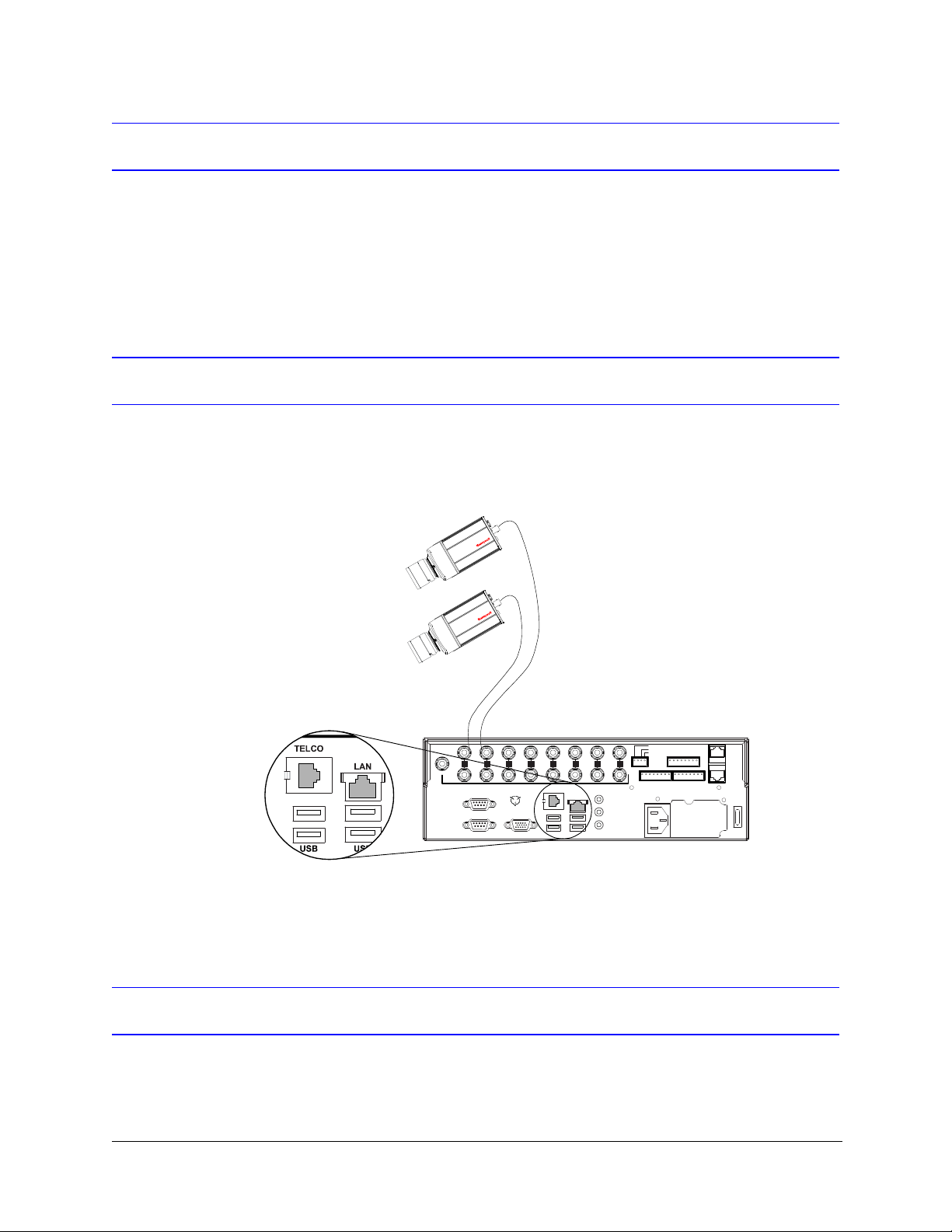
Communications
Connect the Multi-Media LT DVR either to a network, to a telephone line, or both (see
Figure 1-1 for connection details).
Figure 1-1 Telephone Line (TELCO, North America Only) or Network (LAN)
For more information, see Testing a Dial-Up Connection in the Field on page 36.
Powering the Multi-Media LT DVR
Honeywell recommends that you apply power to the Multi-Media LT DVR through an
uninterruptible power supply (UPS). For more information, see Powering Up on page 28.
20

Caution In Europe, a UPS is required to meet EN50130-4 Euro Norm.
Configuring the Multi-Media LT DVR
Whether you plan to operate the DVR onsite (using LocalView) or remotely (using View
software through a network connection), you need to set up LocalView.
Note For remote operations using only dial-up, you do not need to set up
LocalView.
Rapid Eye™ LT DVR Installation Guide
Next Steps
The following chapters in this guide provide detailed procedures and reference materials,
starting with Chapter 2, Installation.
Operating the DVR Remotely
If you plan to perform a quick connection after the installation, to connect remotely to Rapid
Eye LT DVRs, you should refer to the Rapid Eye™ Multi-Media Digital Video Recorder
System Administrator Guide, and the Rapid Eye™ Multi-Media Digital Video Recorder
System Common Operator Guide, for the necessary procedures.
Note After installing the Rapid Eye software, documentation about Rapid Eye
Multi-Media LT (REM) is available at the operator’s PC. Click Start
Programs Rapid Eye Multi-Media LT x.x Documentation REM
publication title (choose the document you want to view).
You can also consult the Rapid Eye™ Multi-Media Digital Video Recorder Remote View
Operator Guide, which offers more procedures and reference material.
All
Document 800-07766V1 Rev A 21
02/11

Introduction
Web Site
To learn more about Honeywell products that can be used with your Multi-Media LT system
or to consult our library of user documentation, go to www.honeywellvideo.com.
Storage Estimator
The Storage Estimator is installed along with the Rapid Eye software. To run the storage
estimator, install the Rapid Eye software, and then:
1. Select the Start menu All Programs Rapid Eye Multi-Media LT x.x.
2. Click Storage Estimator.
3. Click OK on the About Storage Estimator window that appears.
4. Change the recording options in the Estimator, as needed, and click Apply Options
to obtain an estimate of your system’s storage capacity.
See the Rapid Eye™ Multi-Media Digital Video Recorder System Administrator Guide,
for more information on the storage estimator.
Background Information
Caution Effective video feeds are a major component of any CCTV system.
Planning for camera position, distance from subject, angle and lighting
can be as critical as operating your Multi-Media LT DVR. For audio:
planning microphone position, distance from subject and alarm bells can
also be critical. Consult your camera and audio suppliers for optimal
hardware setup.
Caution In LocalView, if the language settings are changed more than fifty (50)
times, Honeywell recommends rebooting the Rapid Eye LT DVR.
22

2
Installation
This chapter provides procedures for installing a Rapid Eye Multi-Media LT DVR system in
the field.
Before You Begin
It is important that you follow the procedures in this chapter in the order listed. Please read
this guide carefully before starting the installation. Keep this guide for future reference.
Unpack Everything
Check that the items received match those listed on the order form and packing slip. The
items you receive will depend on your unique system requirements. Your kit can include:
Table 2-1 Contents of Rapid Eye Hardware Kit 100-02557
Item
a
Part #
Power Cord (North America only) P8137
Network CAT5 cable, RJ45 connections, 2 m length K9530
Modem cable, RJ11 (North America only) CB00173
Terminal block plug for FAULT RELAY, 4 positions, 3.5 mm K9531-4
3 Terminal block plugs for ALARM inputs and CONTROL
outputs, 8 positions, 3.5 mm
Screwdriver, slim, for terminal blocks K9536
Mouse, two-button 100-01280
Mouse pad K0007V1
CD, Rapid Eye One Admin software 100-02809
Documentation CD, includes all documents needed for your unit 100-02808
a
One of each is provided, unless otherwise noted.
Document 800-07766V1 Rev A 23
02/11
K9531-8

Installation
Unpack the DVR
1. Open the box and remove the Multi-Media LT DVR, the power cord, and the other
contents of the box (see Table 2-1).
2. Remove the plastic bag that surrounds the DVR.
3. Store the box and packaging materials.
Caution Do not remove factory seals on a Rapid Eye Multi-Media LT DVR. Doing so will
void your warranty.
There are no user-serviceable parts inside.
Damaged Unit or Missing Goods
In the unlikely event that the DVR is damaged, or parts are missing:
1. Make a note of the DVR serial number, located on a sticker on the bottom of the DVR.
2. Call your Rapid Eye supplier to describe the problem. The supplier will ask for the
DVR serial number and will assign a Return Merchandise Authorization (RMA)
number.
3. Make a note of the RMA.
4. Repack the DVR in its box, along with the other contents.
5. Prominently display the RMA on the shipping carton.
6. Return the packaged DVR to the location specified by your supplier.
Overview of the Installation Procedure
After unpacking the DVR:
1. Determine the best place to install and the ideal orientation of the Multi-Media LT unit
(horizontal or vertical). The unit is shipped ready to install in a horizontal position. See
Appendix C, Horizontal and Vertical Unit Installations, on page 65, for more information
on vertical installations.
2. Connect one or more cameras to the DVR.
3. According to the communications that you plan to use, connect the DVR either to a
telephone line, your local area network (LAN), or both.
4. Power up the camera(s) and the DVR.
5. For network connections, assign a TCP/IP Address to the DVR using:
• The LocalView interface
• A Mouse (included)
• A Monitor (not included)
6. Field-test the connection to the DVR.
Field technicians tasked with the initial steps of an installation will find these steps
expanded and explained in more detail in Connecting Cameras, page 20, and
Communications, page 20.
24
 Loading...